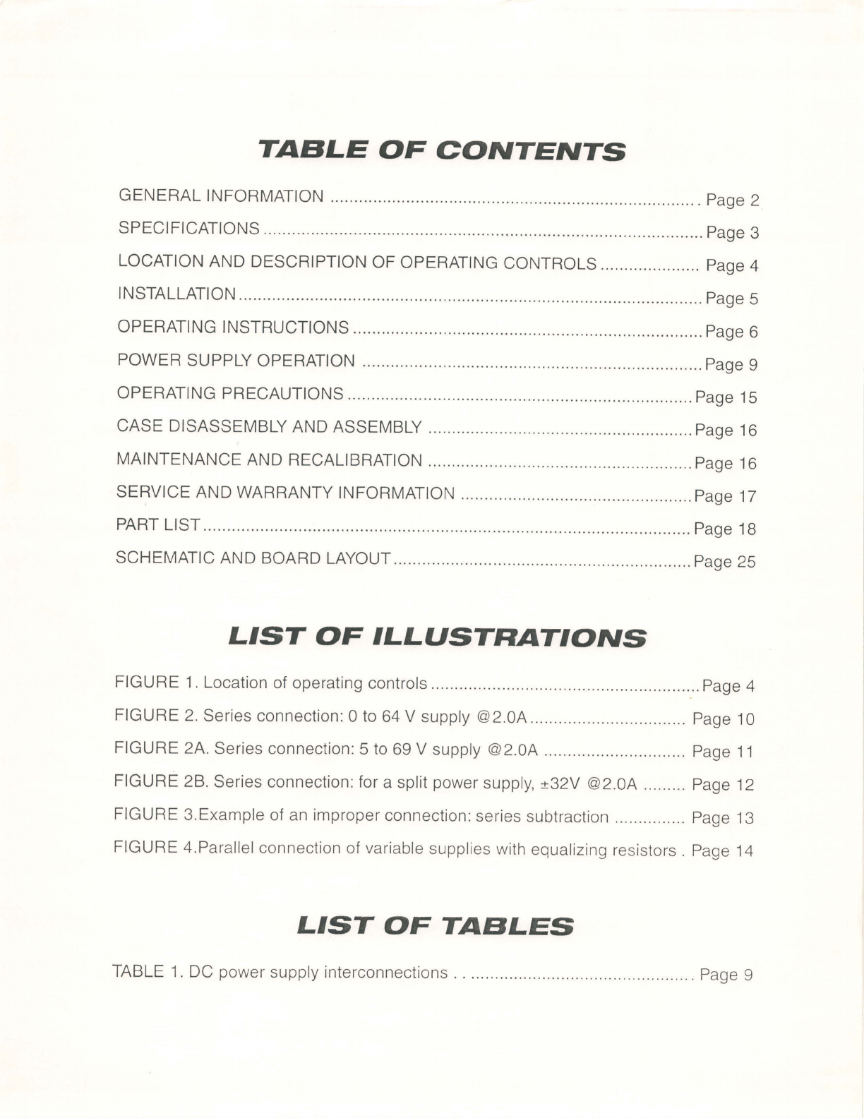
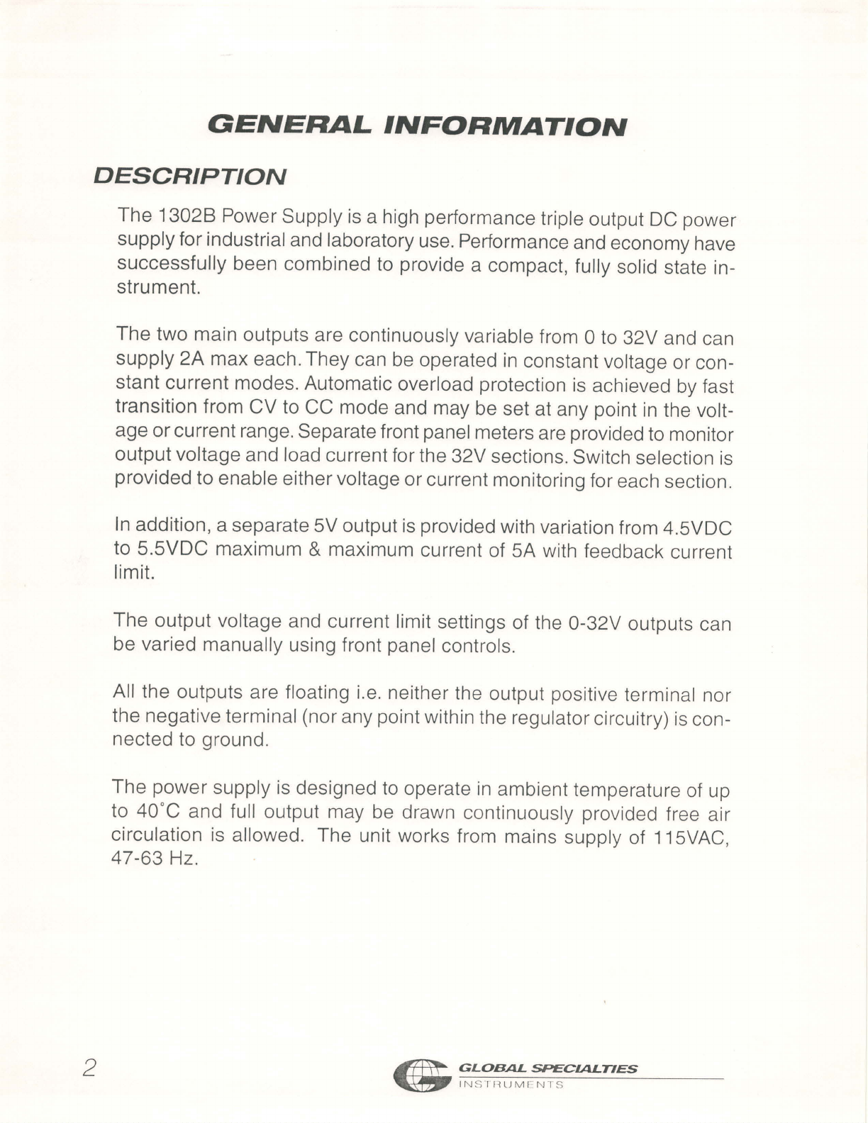
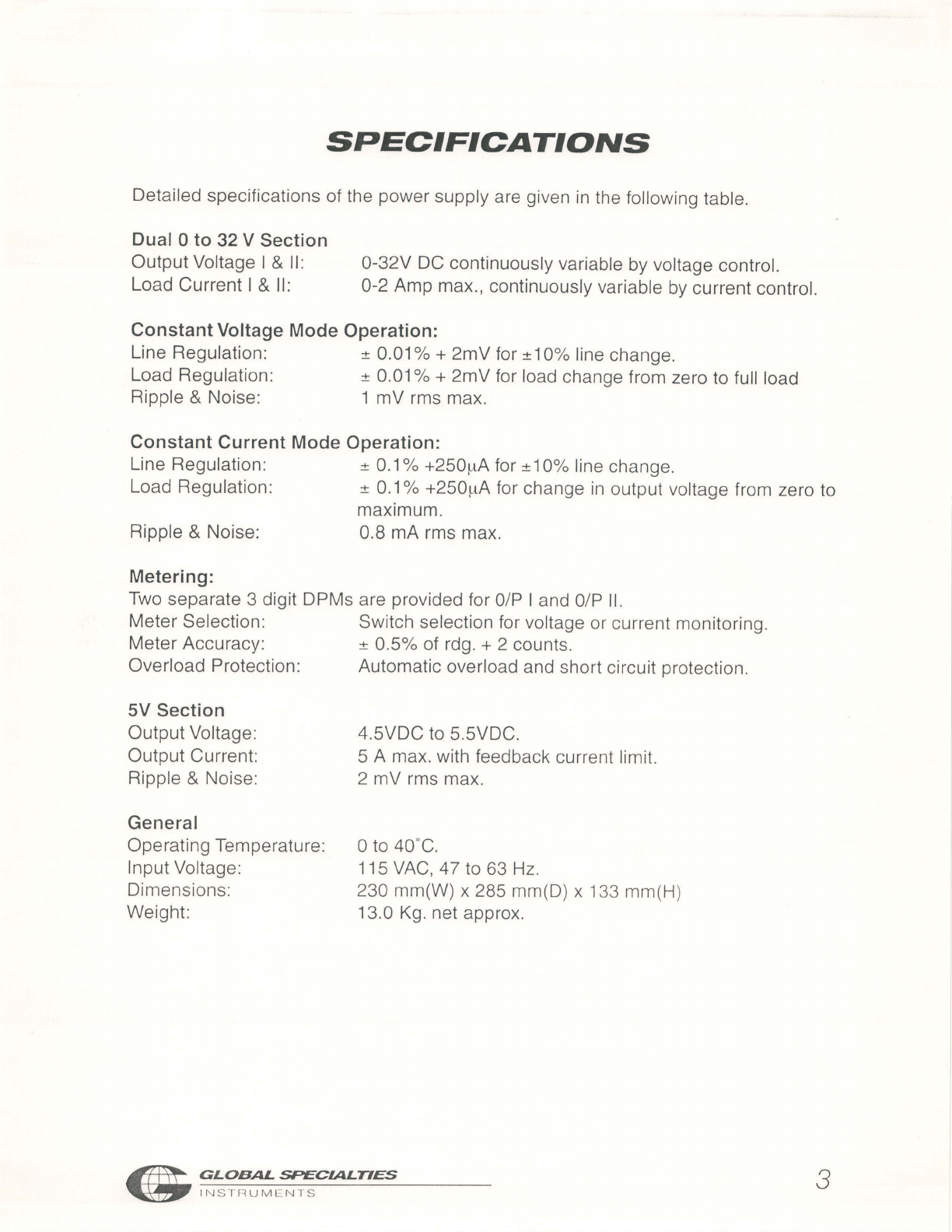
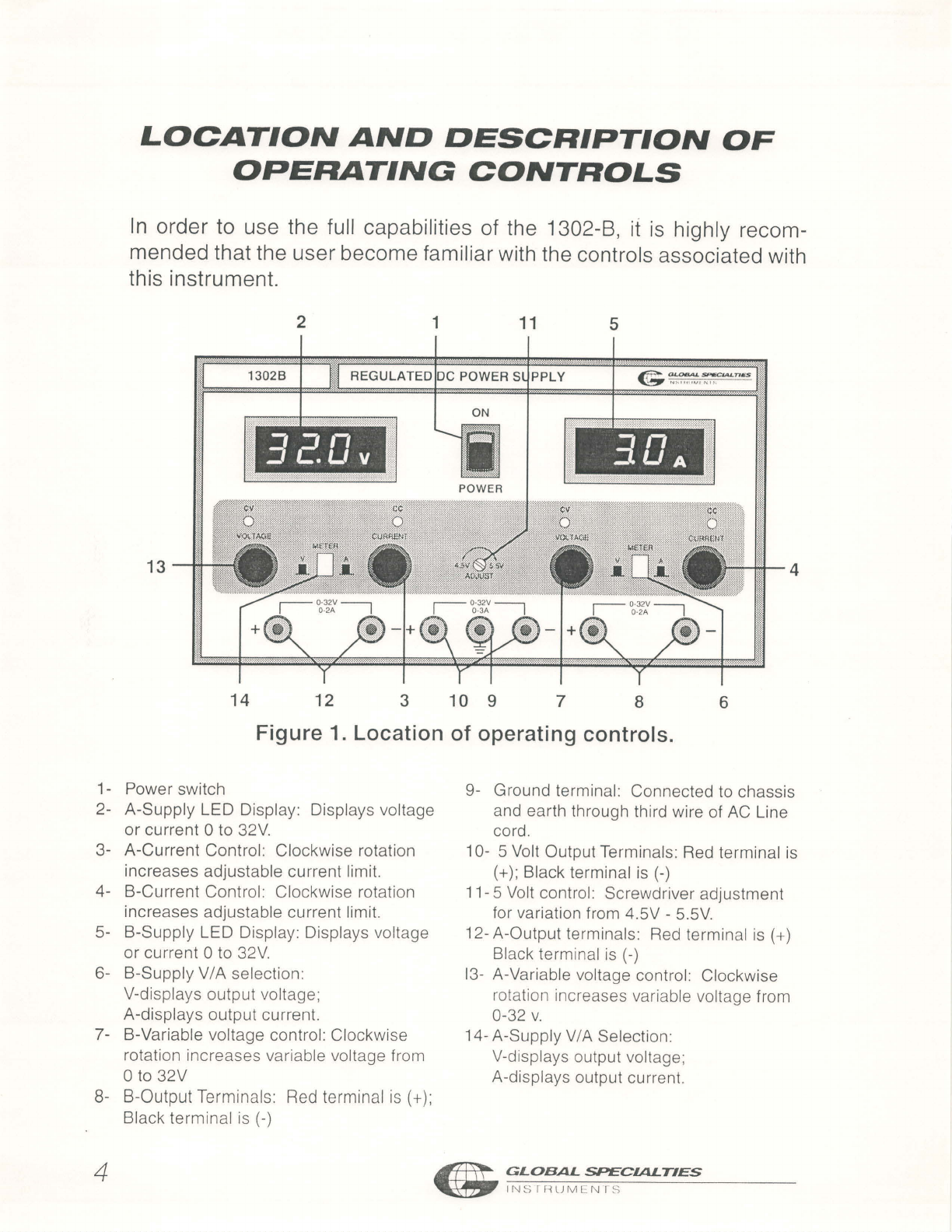
Global Specialties 1302B User manual
Other Global Specialties Power Supply manuals

Global Specialties
Global Specialties 1505 User manual

Global Specialties
Global Specialties 1315D User manual

Global Specialties
Global Specialties 1310 User manual

Global Specialties
Global Specialties 1335 User manual

Global Specialties
Global Specialties 1320 User manual

Global Specialties
Global Specialties 1415 User manual

Global Specialties
Global Specialties 1412 User manual

Global Specialties
Global Specialties 1403 User manual

Global Specialties
Global Specialties 1410 User manual

Global Specialties
Global Specialties 1368 User manual