GM International D5098S User manual

D5098 - 5 A SIL 3 Relay Out Module for NE Load G.M. International ISM0305-2
5 A SIL 3 Relay Output Module for NE Load,
DIN-Rail and Termination Board,
Models D5098S, D5098D
D5098S - D5098D
INSTRUCTION MANUAL

2 D5098 - 5 A SIL 3 Relay Out Module for NE Load G.M. International ISM0305-2
Technical Data
Characteristics
Input: 24 Vdc nom (21.6 to 27.6 Vdc) reverse polarity protected, ripple within voltage limits ≤5 Vpp.
Current consumption @ 24 V: 45 mA for D5098S, 25 mA/channel D5098D typical (D5098D could be incompatible with PLC/DCS DO cards, requiring a load impedance below 1 kΩ).
Power dissipation @ 24 V: 1.1 W for D5098S, 0.6 W/channel for D5098D typical.
Isolation (Test Voltage): Output/Input 1.5 KV; Input/Input 500 V; Output/Output 1.5 KV
Outputs: 1 voltage free SPDT relay contact identified with outputs: Out 1 (NO contact) terminals 7-8 and Service Load Out 1 (NC contact) terminals 7-11;
1 voltage free SPDT relay contact identified with outputs Out 2 (NO contact) terminals 9-10 and Service Load Out 2 (NC contact) terminals 9-12 (only for D5098D).
Terminals 7-8 (Out 1) and 9-10 (Out 2, only for D5098D) are open when relay is de-energized , closed in energized relay condition.
Service load outputs (not SIL) at terminals 7-11 and 9-12 (only for D5098D) are normally closed when relay is de-energized, open in energized relay condition.
Contact material: Ag Alloy (Cd free), gold plated.
Contact rating: 5 A 250 Vac 1250 VA, 5 A 250 Vdc 140 W (resistive load). Min.switching current 1 mA.
Contact inrush current: 6 A at 24 Vdc, 250 Vac.
DC and AC Load breaking capacity:
Mechanical / Electrical life: 5 * 106/ 3 * 104operation, typical.
Operate / Release time: 30 ms / 30 ms typical.
Frequency response: 10 Hz maximum.
Compatibility:
CE mark compliant, conforms to Directives: 2014/34/EU ATEX, 2014/30/EU EMC, 2014/35/EU LVD, 2011/65/EU RoHS.
Environmental conditions:
Operating: temperature limits – 40 to + 70 °C, relative humidity 95 %, up to 55 °C.
Storage: temperature limits - 45 to + 80 °C.
Safety Description:
ATEX: II 3G Ex nA nC IIC T4 Gc.
IECEx: Ex nA nC IIC T4 Gc
non-sparking electrical equipment. -40 °C ≤Ta ≤70 °C.
Approvals:
IMQ 17 ATEX 009 X conforms to EN60079-0, EN60079-15.
IECEx IMQ 17.0006X conforms to IEC60079-0, IEC60079-15.
TÜV Certificate No. C-IS-272994-01 SIL 3 conforms to IEC61508:2010 Ed.2 .
TÜV Certificate No. C-IS-236198-09, SIL 3 Functional Safety Certificate conforms to IEC61508:2010 Ed.2, for Management of Functional Safety.
Mounting: T35 DIN-Rail according to EN50022 or on customized Termination Board.
Weight: about 150 g D5098D, about 110 g D5098S.
Connection: by polarized plug-in disconnect screw terminal blocks to accommodate
terminations up to 2.5 mm2.
Location: installation in Safe Area or Zone 2, Group IIC T4
Protection class: IP20.
Dimensions: Width 12.5 mm, Depth 123 mm, Height 120 mm.
General Description:
The single and dual channel D5098S and D5098D Relay Output modules are suitable for the switching of safety related circuits, up to SIL 3 level according to IEC 61508:2010 Ed.2,
for high risk industries.
They provide isolation between input and output contacts.
D5098S provides one NO contact for normally energized loads and one NC contact for service purposes.
D5098D provides two NO contacts for two normally energized loads and two NC contact for service purposes.
Mounting on standard DIN-Rail or on customized Termination Boards, in Safe Area or in Zone 2.
Functional Safety Management Certification:
G.M. International is certified by TUV to conform to IEC61508:2010
part 1 clauses 5-6 for safety related systems up to and included SIL3.
FSM
SIL 3
0.20.0
V (V)
I (A)
10
20
30
40
50
100
0.3 0.4 0.5 1 2 3
Resistive
Load
200
4
300
250
0.1 56
DC
resistive
AC
Resistive

3
D5098 - 5 A SIL 3 Relay Out Module for NE LoadG.M. International ISM0305-2
Ordering information
Front Panel and Features
SIL 3 (low demand mode of operation) for NE Load according to IEC 61508:2010 Ed.2, with Tproof = 14 / 20 yrs (10 / 20 % of total SIF) and
PFDavg (1 year) = 7.02 E-06, SFF = 98.71 %.
SIL 3 (high demand mode of operation) for NE Load according to IEC 61508:2010 Ed.2, with PFH = 1.60 E-09 h-1.
Systematic capability SIL 3.
Installation in Zone 2.
Compatible with DCS/PLC pulse testing.
SIL 3 contact for NE Load and contact for service purposes.
6 A inrush current at 24 Vdc / 250 Vac.
Input/Output isolation.
EMC Compatibility to EN61000-6-2, EN61000-6-4, EN61326-1, EN61326-3-1 for safety system.
ATEX, IECEx, TÜV Certifications.
TÜV Functional Safety Certification.
Simplified installation using standard DIN-Rail and plug-in terminal blocks or customized Termination Boards.
DIN-Rail accessories: Cover and fix MCHP196
Terminal block male MOR017 Terminal block female MOR022
Terminal block connections
(CM1) 1st pole of Out 1 (NO contact) for NE Load or (NC contact) for Service
SAFE AREA
(NO1) 2nd pole of Out 1 (NO contact) for NE Load
(CM2) 1st pole of Out 2 (NO contact) for NE Load or (NC contact) for Service
7
8
9
+ Input
1
- Input
2
+ Input (only for D5098D)
3
- Input (only for D5098D)
4
(NO2) 2nd pole of Out 2 (NO contact) for NE Load
10
(NC1) 2nd pole of Out 1 (NC contact) for Service load
(NC2) 2nd pole of Out 2 (NC contact) for Service load
11
12
Not used
5
Not used
6
D2 channels
S1 channel
Model: D5098
7 8
9 10
11 12
12
34
D5098
7 8
1 2
SIL 3
9 10
STS 1
11 12
3 4
STS 2

4 D5098 - 5 A SIL 3 Relay Out Module for NE Load G.M. International ISM0305-2
Function Diagram
SAFE AREA, ZONE 2 GROUP IIC T4
Relay contacts shown in de-energized position.
Terminals 7-8 and 9-10 are open; terminals 7-11 and 9-12 are closed.
To prevent relay contacts from damaging, connect an external protection (fuse or similar),
chosen according to the relay breaking capacity diagram.
MODEL D5098D
+
Out 1 (NO contact)
(NO1) 8
(CM1) 7
In 1
1
2
Service Load Out 1
Termination
board
connector
Not SIL (NC1) 11
+
Out 2 (NO contact)
(NO2) 10
(CM2) 9
In 2
3
4
Service Load Out 2
Not SIL (NC2) 12
SIL 3
SIL 3
2 Inputs, 2 Loads

5
D5098 - 5 A SIL 3 Relay Out Module for NE LoadG.M. International ISM0305-2
Function Diagram
SAFE AREA, ZONE 2 GROUP IIC T4
Relay contacts shown in de-energized position.
Terminals 7-8 are open; terminals 7-11 are closed.
To prevent relay contacts from damaging, connect an external protection (fuse or similar),
chosen according to the relay breaking capacity diagram.
MODEL D5098S
+
Out 1 (NO contact)
(NO1) 8
(CM1) 7
In 1
1
2
Service Load Out 1
Termination
board
connector
Not SIL (NC1) 11
SIL 3
MODEL D5098D
+
Out 1 (NO contact)
(NO1) 8
(CM1) 7
In 1
1
2
Service Load Out 1
Termination
board
connector
Not SIL (NC1) 11
Out 2 (NO contact)
(NO2) 10
(CM2) 9
3
4
Service Load Out 2
Not SIL (NC2) 12
SIL 3
SIL 3
Relay contacts shown in de-energized position.
Terminals 7-8 and 9-10 are open; terminals 7-11 and 9-12 are closed.
1 Input, 2 Loads

6 D5098 - 5 A SIL 3 Relay Out Module for NE Load G.M. International ISM0305-2
Warning
Operation
The single and dual channel D5098S and D5098D Relay Output modules are suitable for the switching of safety related circuits, up to SIL 3 level according to IEC 61508:2010 Ed.2,
for high risk industries. They provide isolation between input and output contacts. D5098S provides one NO contact for normally energized loads and one NC contact for service
purposes. D5098D provides two NO contacts for two normally energized loads and two NC contact for service purposes. When driving signals (terminals 1-2 for Channel 1 and 3-4 for
Channel 2, only for D5098D) are low (0 Vdc), the relays are de-energized, contacts at terminals 7-8 (for Channel 1) and 9-10 (for Channel 2) are open and loads are de-energized. When
driving signals are high (24 Vdc), the relays are energized, contacts at terminals 7-8 and 9-10 are closed and loads are energized. For each channel, presence of status of input / output
channel (energized or de-energized) is displayed by yellow LED.
Installation
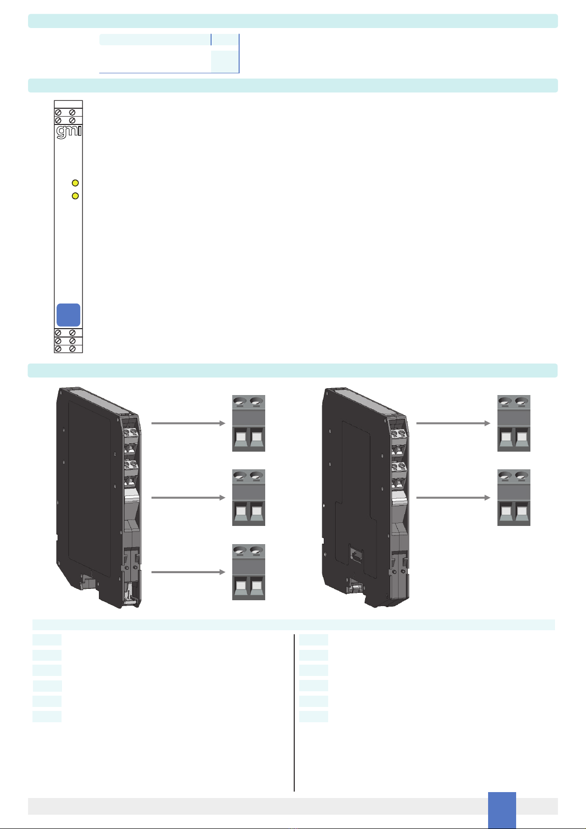
D5098S and D5098D are relay output modules housed in a plastic enclosure suitable for installation on T35 DIN-Rail according to EN50022, or on customized Termination Board.
D5098 unit can be mounted with any orientation over the entire ambient temperature range. Electrical connection of conductors up to 2.5 mm² are accommodated by polarized
plug-in removable screw terminal blocks which can be plugged in/out into a powered unit without suffering or causing any damage (for Zone 2 installations check the area to be
nonhazardous before servicing). The wiring cables have to be proportionate in base to the current and the length of the cable. On the section “Function Diagram” and enclosure side a
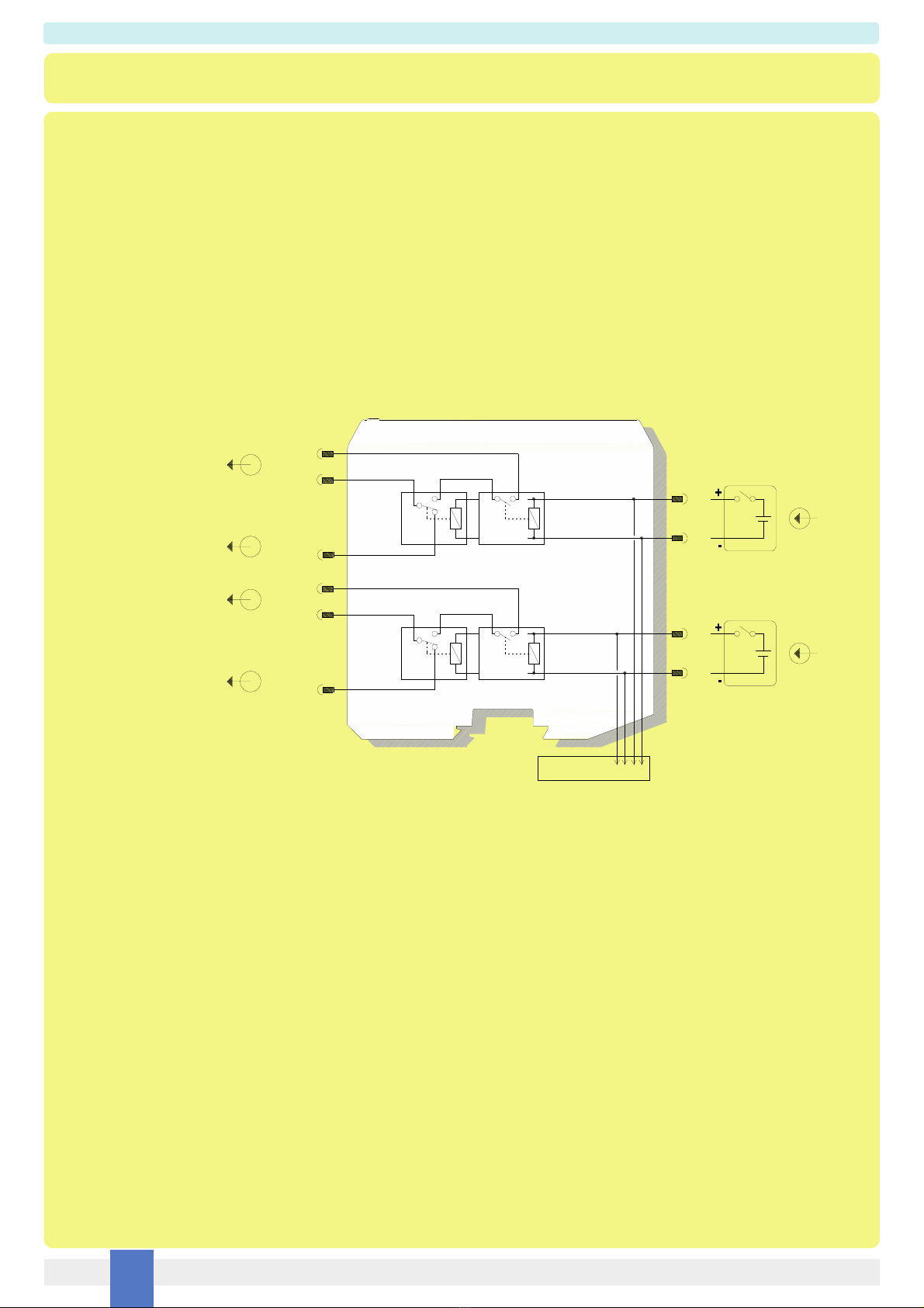
block diagram identifies all connections. Identify the function and location of each connection terminal using the wiring diagram on the corresponding section, as an example:
Connect positive input at terminal “1” and negative input at “2” for Channel 1.
Connect positive input at terminal “3” and negative input at “4” for Channel 2 (only for D5098D).
For channel 1 output, connect positive or AC load supply line to contact common pole at terminal “7”.
Always for channel 1 output, connect SIL 3 NE load between negative or AC load supply line and the contact pole at terminal “8”.
In addition, if it’s necessary, connect service load (Not SIL) between negative or AC load supply line and the contact pole at terminal “11”.
For channel 2 output, connect positive or AC load supply line to contact common pole at terminal “9”.
Always for channel 1 output, connect SIL 3 NE load between negative or AC load supply line and the contact pole at terminal “10”.
In addition, if it’s necessary, connect service load (Not SIL) between negative or AC load supply line and the contact pole at terminal “12”.
Installation and wiring must be in accordance to the relevant national or international installation standards (e.g. IEC/EN60079-14 Electrical apparatus for explosive gas atmospheres
Part 14: Electrical installations in hazardous areas (other than mines)), make sure that conductors are well isolated from each other and do not produce any unintentional connection.
For each contact, checking the load rating to be within the contact maximum rating 5 A 250 Vac 1250 VA, 5 A 250 Vdc 140 W (resistive load). To prevent relay contacts from
damaging, connect an external protection (fuse or similar), chosen according to the relay breaking capacity diagram on data sheet. The enclosure provides, according to
EN60529, an IP20 minimum degree of protection (or similar to NEMA Standard 250 type 1). For non-hazardous location, the unit shall be installed in an area of not more than pollution
degree 2. For hazardous location, the unit shall be installed in a certified Ex enclosure with a minimum ingress protection of at least IP54 in accordance with EN/IEC60079-15. Units must
be protected against dirt, dust, extreme mechanical (e.g. vibration, impact and shock) and thermal stress, and casual contacts. If enclosure needs to be cleaned use only a cloth lightly
moistened by a mixture of detergent in water. Electrostatic Hazard: to avoid electrostatic hazard, the enclosure of D5098 must be cleaned only with a damp or antistatic cloth.
Any penetration of cleaning liquid must be avoided to prevent damage to the unit. Any unauthorized card modification must be avoided. According to EN61010, D5098 must be connect-
ed to SELV or SELV-E power supplies. Relay output contact must be connected to load non exceeding category II overvoltage limits. Warning: de-energize main power source (turn
off power supply voltage) and disconnect plug-in terminal blocks before opening the enclosure to avoid electrical shock when connected to live hazardous potential.
D5098S and D5098D are electrical apparatus installed into standard EN50022 T35 DIN-Rail located in Safe Area or Zone 2, Group IIC, Temperature Classification T4, Hazardous Area
(according to EN/IEC60079-15) within the specified operating temperature limits Tamb - 40 to +70 °C. D5098 must be installed, operated and maintained only by qualified personnel, in
accordance to the relevant national/international installation standards (e.g. IEC/EN60079-14 Electrical apparatus for explosive gas atmospheres - Part 14: Electrical installations in
hazardous areas (other than mines)), following the established installation rules. De-energize power source (turn off power supply voltage) before plug or unplug the terminal blocks
when installed in Hazardous Area or unless area is known to be nonhazardous. Warning: substitution of components may impair suitability for Zone 2. Warning: de-energize
main power source (turn off power supply voltage) and disconnect plug-in terminal blocks before opening the enclosure to avoid electrical shock when connected to live
hazardous potential. Explosion Hazard: to prevent ignition of flammable or combustible atmospheres, disconnect power before servicing or unless area is known to be
nonhazardous.
Provision shall be assured, external to the equipment by the installation location, to provide a transient protection to not exceeding 120V or 140% of the peak rated voltage (whichever is
the greater) at the power supply terminals. Failure to properly installation or use of the equipment may risk to damage the unit or severe personal injury. The unit cannot be repaired by
the end user and must be returned to the manufacturer or his authorized representative. Any unauthorized modification must be avoided.
Start-up
Before powering the unit check that all wires are properly connected, particularly supply conductors and their polarity, input and output wires. Check conductors for exposed wires that
could touch each other causing dangerous unwanted shorts. Enabling each input, the related channel status yellow led must be lit and related load circuit must be energized because
relay output contacts are closed. Instead, disabling each input, the related channel status yellow led must be turned off and related load circuit must be de-energized because relay
output contacts are open.
This manual suits for next models
1
Table of contents
Other GM International Control Unit manuals
Popular Control Unit manuals by other brands

Siemens
Siemens VVI46 /2 Series Mounting instructions

Anritsu
Anritsu Network Master Pro MT1040A Operation manual

System Sensor
System Sensor M210EA-CZ manual

Behringer
Behringer 130 DUAL VCA quick start guide

Hydro Instruments
Hydro Instruments PRV-71H Series Operation and maintenance manual

Kitz
Kitz F14A Operation, maintenance, and installation instructions