GM International D5290S-079 User manual

D5290S-079 - 5 A SIL 3 Relay Output Module (115 Vac coil voltage) G.M. International ISM0153-2
5 A SIL 3 Relay Output Module for NE or ND Loads,
with NE Relay condition,
DIN-Rail,
Model D5290S-079
D5290S-079
INSTRUCTION MANUAL
INSTRUCTION MANUAL

2 D5290S-079 - 5 A SIL 3 Relay Output Module (115 Vac coil voltage) G.M. International ISM0153-2
Technical Data
Characteristics
Input: 115 Vac nom (95 to 130 Vac).
Current consumption @ 115 Vac: 25 mA with relay energized, typical.
Power dissipation: 2.5 W with 115 Vac input voltage, relay energized, typical.
Isolation (Test Voltage): Input / All Outputs: 2.5 KV; Out S_1 & Out P_1 / Out S_3 & Out P_2, Out S_2, Out S_4: 500 V;
Out S_3 & Out P_2 / Out S_2, Out S_4: 500 V; Out S_2 / Out S_4: 500 V.
Output: 2 voltage free SPDT (= NO contact + parallel of 2 NC contacts) relay contacts identified with outputs: Out S_1 & Out P_1 and Out S_3 & Out P_2;
2 voltage free SPST (NO) relay contacts identified with: Out S_2 and Out S_4.
Terminals 13-14 (Out S_1), 15-16 (Out S_2), 21-22 (Out S_4) and 23-24 (Out S_3) are: open when relay is de-energized, closed in energized relay condition.
Terminals 17-18 (Out P_1) and 19-20 (Out P_2) are: closed when relay is de-energized, open in energized relay condition.
Contact material: Ag Alloy (Cd free).
Contact rating: 5 A 250 Vac 1250 VA, 5 A 250 Vdc 175 W (resistive load).
DC Load breaking capacity:
Mechanical / Electrical life: 10 * 106/ 5 * 104operation, typical.
Bounce time NO / NC contact: 4 / 10 ms, typical.
Frequency response: 10 Hz maximum.
Compatibility:
CE mark compliant, conforms to 94/9/EC Atex Directive and to
2004/108/CE EMC Directive.
Environmental conditions:
Operating: temperature limits - 40 to + 60 °C, relative humidity 95 %, up to 55 °C.
Storage: temperature limits - 45 to + 80 °C.
Approvals:
TÜV Certificate No. C-IS-224248-01, SIL 2 / SIL 3 conforms to IEC61508:2010.
Mounting:
T35 DIN-Rail according to EN50022.
Weight: about 145 g.
Connection: by polarized plug-in disconnect screw terminal blocks to accomodate terminations up to 2.5 mm2.
Location: Safe Area / Non Hazardous Location.
Protection class: IP 20.
Dimensions: Width 22.5 mm, Depth 123 mm, Height 120 mm.
General Description:
The D5290S-079 is a relay module suitable for the switching of safety related circuits, up to SIL 3 level according to IEC 61508 for high risk industries.
It provides isolation between input channel and output contacts.
The input channel requires 115 Vac voltage signal to drive the relay coils.
See the following pages for Functional Safety applications with related SIL value.
Mounting on standard DIN-Rail in Safe Area.
0.20.1
V (V)
I (A)
10
20
30
40
50
100
200
300
0.3 0.5 1 2 3
Resistive
Load
45
250

3
D5290S-079 - 5 A SIL 3 Relay Output Module (115 Vac coil voltage)G.M. International ISM0153-2
Ordering Information
Front Panel and Features
• SIL 3 according to IEC 61508 for Tproof = 10 / 20 years (10 / 20 % of total SIF)
with PFDavg (1 year) 7.01 E-06, SFF = 99.00 % for two NE loads (see application n° 1, 2) or a ND load (see application n° 4)
with NE relay condition.
• SIL 2 according to IEC 61508 for Tproof = 7 / 14 years (10 / 20 % of total SIF)
with PFDavg (1 year) 1.40 E-04, SFF = 60.12 % for four NE loads with NE relay condition (see application n° 3).
• 5 A SIL 3 / SIL 2 contacts for NE or ND loads with NE Relay condition
.
• Input/Output isolation.
•
EMC Compatibility to EN61000-6-2, EN61000-6-4, EN61326-1, EN61326-3-1 for safety system.
• TÜV Certification.
• Simplified installation using standard DIN-Rail and plug-in terminal blocks.
Model: D5290S-079 DIN-Rail accessories: Cover and fix MCHP196
Normally Open (NO) contact (Out S_1)
Terminal block connections
SAFE AREA
13
4 3
2 1
13 14 15
16
17 18 19 20
21 22 23 24
14
15
16
17
18
19
20
21
22
23
24
1
3
2
4
Normally Open (NO) contact (Out S_2)
Normally Closed (NC) contact (Out P_1)
Normally Closed (NC) contact (Out P_2)
Normally Open (NO) contact (Out S_4)
Normally Open (NO) contact (Out S_3)
115 Vac Input signal line

4 D5290S-079 - 5 A SIL 3 Relay Output Module (115 Vac coil voltage) G.M. International ISM0153-2
Applications
Function Diagram
SAFE AREA
To prevent relay contacts from damaging, connect an external protection (fuse or similar),
chosen according to the relay breaking capacity diagram.
Relay contacts shown in de-energized position.
Terminals 13-14, 15-16, 21-22 and 23-24 are open.
Terminals 17-18 and 19-20 are closed.
See the following pages for Functional Safety applications with related SIL value.
MODEL D5290S-079
1
2
3
4
22
21
19
20
23
24
Out S_1 (NO contact)
13
14
Out P_1 (NC contact)
17
18
16
15
Out S_2 (NO contact)
Out S_4 (NO contact)
Out P_2 (NC contact)
Out S_3 (NO contact)
In

5
D5290S-079 - 5 A SIL 3 Relay Output ModuleG.M. International ISM0153-2
Functional Safety Manual and Applications
5
D5290S-079 - 5 A SIL 3 Relay Output Module (115 Vac coil voltage)G.M. International ISM0153-2
Functional Safety Manual and Applications
22
21
20
23
24-19
18-13
17
14
Application D5290S-079 - SIL 3 Load Normally Energized Condition (NE) and Normally Energized Relay:
one common driving signal from PLC for both NE loads (A and B), with interruption of both load supply lines
B
NE
Load
SIL 3
PLC
Output ON
115 Vac
Normal state operation De-energized to trip operation
Service
Load B
(Not SIL)
A NE
Load
SIL 3
16
15
Service
Load A
(Not SIL)
22
21
20
23
24-19
18-13
17
14
B
NE
Load
SIL 3
PLC
Output OFF
0 Vac
Service
Load B
(Not SIL)
A NE
Load
SIL 3
16
15
Service
Load A
(Not SIL)
- / AC (for load A and its service load)
+ / AC (for load A and its service load) + / AC (for load B and its service load)
- / AC (for load B and its service load)
+ / AC (for load A and its service load) + / AC (for load B and its service load)
- / AC (for load A and its service load) - / AC (for load B and its service load)
1)
Description:
Input Signal from PLC/DCS is normally High (115 Vac) and is applied to pins 1-2 or 3-4 in order to Normally Energize (NE) the internal relays.
Input Signal from PLC/DCS is Low (0 Vac) during “de-energize to trip” operation, in order de-energize the internal relays.
Load A (and Load B if present) is Normally Energized (NE) therefore its safe state is to be de-energized.
Disconnection of Loads A and B is done on both supply lines.
Service Load A (and Service Load B if present) is normally de-energized, therefore it energizes during “de-energize to trip” operation.
The following table describes the status (open or closed) of each output contact when input signal is High or Low.
Safety Function and Failure behavior:
D5290S-079 is considered to be operating in Low Demand mode, as a Type A module, having Hardware Fault Tolerance (HFT) = 0.
In the 1st Functional Safety application, the normal state operation of relay module is energized, with NE (Normally Energized) loads.
In case of alarm or request from process, the relay module is de-energized (safe state), de-energizing loads.
The failure behaviour of relay module is described by the following definitions:
□fail-Safe State: it is defined as the output load being de-energized;
□fail Safe: this failure causes the system to go to the defined fail-safe state without a process demand;
□fail Dangerous: failure mode that does not respond to a demand from the process (i.e. being unable to go to the defined fail-safe state), so that the output load remains energized.
In addition, there are other definitions of failure behaviours which are not safety-related:
□fail “No effect”: failure mode of a component that plays a part in implementing the safety function but is neither a safe failure nor a dangerous failure;
□fail “Not part”: failure mode of a component which is not part of the safety function but part of the circuit diagram and is listed for completeness. When calculating the SFF this
failure mode is not taken into account. It is also not considered for the total failure rate evaluation.
T[Proof] = 20 years
PFDavg = 1.40 E-04 Valid for SIL 3
Failure rate table:
Failure category Failure rates (FIT)
λdd = Total Dangerous Detected failures 0.00
λdu = Total Dangerous Undetected failures 1.60
λsd = Total Safe Detected failures 0.00
λsu = Total Safe Undetected failures 158.88
λtot safe = Total Failure Rate (Safety Function) = λdd + λdu + λsd + λsu 160.48
λno effect = “No effect” failures 11.92
λnot part = “Not Part” failures 0.00
λtot device = Total Failure Rate (Device) = λtot safe + λno effect + λnot part 172.40
MTBF (device, single channel) = (1 / λtot device) + MTTR (8 hours) 662 years
MTTFS(Total Safe) = 1 / (λsd + λsu) 718 years
MTTFD(Dangerous) = 1 / λdu 71347 years
MTBF (safety function, single channel) = (1 / λtot safe) + MTTR (8 hours) 711 years
Input Signal
Pins 1-2 or 3-4
Pins
13-14
Pins
15-16
NE Load A (SIL3)
Pins 14-16
NE Load B (SIL 3)
Pins 23-21
Service
Load A
High (115 Vac) Closed Closed Energized Energized De-Energized
Low (0 Vac) Open Open De-Energized De-Energized Energized
Service
Load B
De-Energized
Energized
Pins
23-24
Closed
Open
Pins
21-22
Closed
Open
Operation
Normal
Trip
Pins
17-18
Open
Closed
Pins
19-20
Open
Closed
Failure rates table according to IEC 61508:
λsd λsu λdd λdu SFF
0.00 FIT 158.88 FIT 0.00 FIT 1.60 FIT 99.00%
PFDavg vs T[Proof] table, with determination of SIL supposing module contributes 10% of entire safety function:
T[Proof] = 1 year T[Proof] = 10 years
PFDavg = 7.01 E-06 Valid for SIL 3 PFDavg = 7.01 E-05 Valid for SIL 3
T[Proof] = 20 years
PFDavg = 1.40 E-04 Valid for SIL 2
PFDavg vs T[Proof] table, with determination of SIL supposing module contributes 20% of entire safety function:
T[Proof] = 20 years
PFDavg = 1.40 E-04 Valid for SIL 3

6 D5290S-079 - 5 A SIL 3 Relay Output Module G.M. International ISM0153-2
Functional Safety Manual and Applications
6 D5290S-079 - 5 A SIL 3 Relay Output Module (115 Vac coil voltage) G.M. International ISM0153-2
Functional Safety Manual and Applications
22
21
20
23
24-19
18-13
17
14
Application D5290S-079 - SIL 3 Load Normally Energized Condition (NE) and Normally Energized Relay:
one common driving signal from PLC for both NE loads (A and B), with interruption of only one load supply line
B
NE
Load
SIL 3
PLC
Output ON
115 Vac
Normal state operation De-energized to trip operation
Service
Load B
(Not SIL)
A NE
Load
SIL 3
16
15
Service
Load A
(Not SIL) 22
21
20
23
24-19
18-13
17
14
B
NE
Load
SIL 3
PLC
Output OFF
0 Vac Service
Load B
(Not SIL)
A NE
Load
SIL 3
16
15
Service
Load A
(Not SIL)
+ / AC (for load A and its service load) + / AC (for load B and its service load) + / AC (for load A and its service load) + / AC (for load B and its service load)
- / AC (for load A and its service load) - / AC (for load B and its service load) - / AC (for load A and its service load) - / AC (for load B and its service load)
2)
Input Signal
Pins 1-2 or 3-4
Pins
13-14
Pins
15-16
NE Load A (SIL3)
Pins 15-Supply
NE Load B (SIL 3)
Pins 22-Supply
Service
Load A
High (115 Vac) Closed Closed Energized Energized De-Energized
Low (0 Vac) Open Open De-Energized De-Energized Energized
Service
Load B
De-Energized
Energized
Pins
23-24
Closed
Open
Pins
21-22
Closed
Open
Operation
Normal
Trip
Pins
17-18
Open
Closed
Pins
19-20
Open
Closed
Description:
Input Signal from PLC/DCS is normally High (115 Vac) and is applied to pins 1-2 or 3-4 in order to Normally Energize (NE) the internal relays.
Input Signal from PLC/DCS is Low (0 Vac) during “de-energize to trip” operation, in order de-energize the internal relays.
Load A (and Load B if present) is Normally Energized (NE) therefore its safe state is to be de-energized.
Disconnection of Loads A and B is done by disconnecting one supply line via two separate contacts.
Service Load A (and Service Load B if present) is normally de-energized, therefore it energizes during “de-energize to trip” operation.
The following table describes the status (open or closed) of each output contact when input signal is High or Low.
Safety Function and Failure behavior:
D5290S-079 is considered to be operating in Low Demand mode, as a Type A module, having Hardware Fault Tolerance (HFT) = 0.
In the 2nd Functional Safety application, the normal state operation of relay module is energized, with NE (Normally Energized) loads.
In case of alarm or request from process, the relay module is de-energized (safe state), de-energizing loads.
The failure behaviour of relay module is described by the following definitions:
□fail-Safe State: it is defined as the output load being de-energized;
□fail Safe: this failure causes the system to go to the defined fail-safe state without a process demand;
□fail Dangerous: failure mode that does not respond to a demand from the process (i.e. being unable to go to the defined fail-safe state), so that the output load remains energized.
In addition, there are other definitions of failure behaviours which are not safety-related:
□fail “No effect”: failure mode of a component that plays a part in implementing the safety function but is neither a safe failure nor a dangerous failure;
□fail “Not part”: failure mode of a component which is not part of the safety function but part of the circuit diagram and is listed for completeness. When calculating the SFF this
failure mode is not taken into account. It is also not considered for the total failure rate evaluation.
Failure rate table:
Failure category Failure rates (FIT)
λdd = Total Dangerous Detected failures 0.00
λdu = Total Dangerous Undetected failures 1.60
λsd = Total Safe Detected failures 0.00
λsu = Total Safe Undetected failures 158.88
λtot safe = Total Failure Rate (Safety Function) = λdd + λdu + λsd + λsu 160.48
λno effect = “No effect” failures 11.92
λnot part = “Not Part” failures 0.00
λtot device = Total Failure Rate (Device) = λtot safe + λno effect + λnot part 172.40
MTBF (device, single channel) = (1 / λtot device) + MTTR (8 hours) 662 years
MTTFS(Total Safe) = 1 / (λsd + λsu) 718 years
MTTFD(Dangerous) = 1 / λdu 71347 years
MTBF (safety function, single channel) = (1 / λtot safe) + MTTR (8 hours) 711 years
Failure rates table according to IEC 61508:
λsd λsu λdd λdu SFF
0.00 FIT 158.88 FIT 0.00 FIT 1.60 FIT 99.00%
PFDavg vs T[Proof] table, with determination of SIL supposing module contributes 10% of entire safety function:
T[Proof] = 1 year T[Proof] = 10 years
PFDavg = 7.01 E-06 Valid for SIL 3 PFDavg = 7.01 E-05 Valid for SIL 3
T[Proof] = 20 years
PFDavg = 1.40 E-04 Valid for SIL 2
PFDavg vs T[Proof] table, with determination of SIL supposing module contributes 20% of entire safety function:
T[Proof] = 20 years
PFDavg = 1.40 E-04 Valid for SIL 3

7
D5290S-079 - 5 A SIL 3 Relay Output ModuleG.M. International ISM0153-2
Functional Safety Manual and Applications
7
D5290S-079 - 5 A SIL 3 Relay Output Module (115 Vac coil voltage)G.M. International ISM0153-2
Functional Safety Manual and Applications
22
21
20
23
24-19
18-13
17
14
Application D5290S-079 - SIL 2 Load Normally Energized Condition (NE) and Normally Energized Relay:
one common driving signal from PLC for all NE loads (A, B, C and D), with interruption of only one load supply line
D
NE
Load
SIL 2
PLC
Output ON
115 Vac
Normal state operation De-energized to trip operation
Service
Load B
(Not SIL)
A NE
Load
SIL 2
16
15
Service
Load A
(Not SIL)
C NE
Load
SIL 2
B
NE
Load
SIL 2
+ / AC (for load C) + / AC (for load B
and its service
load)
+ / AC (for load D)
- / AC (for load C) - / AC (for load D)
- / AC
(for load A and
its service load)
- / AC
(for load B and
its service load)
22
21
20
23
24-19
18-13
17
14
D
NE
Load
SIL 2
PLC
Output OFF
0 Vac
Service
Load B
(Not SIL)
A NE
Load
SIL 2
16
15
Service
Load A
(Not SIL)
C NE
Load
SIL 2
B
NE
Load
SIL 2
+ / AC
(for load A
and service
load A)
+ / AC (for load C) + / AC (for load B
and its service
load)
+ / AC (for load D)
- / AC (for load C) - / AC (for load D)
- / AC
(for load A
and its service
- / AC
(for load B and
its service load)
3)
Input Signal
Pins 1-2 or 3-4
Pins
13-14
Pins
15-16
NE Load A
(SIL 2)
Pins 14-Supply
NE Load C
(SIL 2)
Pins 16-Supply
Service
Load A
High (115 Vac) Closed Closed Energized Energized De-Energized
Low (0 Vac) Open Open De-Energized De-Energized Energized
Service
Load B
De-Energized
Energized
Pins
21-22
Closed
Open
Pins
23-24
Closed
Open
Operation
Normal
Trip
Pins
17-18
Open
Closed
Pins
19-20
Open
Closed
NE Load B
(SIL 2)
Pins 23-Supply
Energized
De-Energized
NE Load D
(SIL 2)
Pins 21-Supply
Energized
De-Energized
Description:
Input Signal from PLC/DCS is normally High (115 Vac) and is applied to pins 1-2 or 3-4 in order to Normally Energize (NE) the internal relays.
Input Signal from PLC/DCS is Low (0 Vac) during “de-energize to trip” operation, in order de-energize the internal relays.
Load A (and Load B, C, D if present) is Normally Energized (NE) therefore its safe state is to be de-energized.
Disconnection of Loads A, B, C, D is done by disconnecting one supply line.
Service Load A (and Service Load B if present) is normally de-energized, therefore it energizes during “de-energize to trip” operation.
The following table describes the status (open or closed) of each output contact when input signal is High or Low.
Safety Function and Failure behavior:
D5290S-079 is considered to be operating in Low Demand mode, as a Type A module, having Hardware Fault Tolerance (HFT) = 0.
In the 3rd Functional Safety application, the normal state operation of relay module is energized, with NE (Normally Energized) loads.
In case of alarm or request from process, the relay module is de-energized (safe state), de-energizing loads.
The failure behaviour of relay module is described by the following definitions:
□fail-Safe State: it is defined as the output load being de-energized;
□fail Safe: this failure causes the system to go to the defined fail-safe state without a process demand;
□fail Dangerous: failure mode that does not respond to a demand from the process (i.e. being unable to go to the defined fail-safe state), so that the output load remains energized.
In addition, there are other definitions of failure behaviours which are not safety-related:
□fail “No effect”: failure mode of a component that plays a part in implementing the safety function but is neither a safe failure nor a dangerous failure;
□fail “Not part”: failure mode of a component which is not part of the safety function but part of the circuit diagram and is listed for completeness. When calculating the SFF this
failure mode is not taken into account. It is also not considered for the total failure rate evaluation.
+ / AC
(for load A
and service
load A)
Failure rates table according to IEC 61508:
λsd λsu λdd λdu SFF
0.00 FIT 48.24 FIT 0.00 FIT 32.00 FIT 60.12%
PFDavg vs T[Proof] table, with determination of SIL supposing module contributes 10% of entire safety function:
T[Proof] = 1 year T[Proof] = 7 years
PFDavg = 1.40 E-04 Valid for SIL 2 PFDavg = 9.81 E-04 Valid for SIL 2
T[Proof] = 20 years
PFDavg = 2.80 E-03 Valid for SIL 1
PFDavg vs T[Proof] table, with determination of SIL supposing module contributes 20% of entire safety function:
Failure rate table:
Failure category Failure rates (FIT)
λdd = Total Dangerous Detected failures 0.00
λdu = Total Dangerous Undetected failures 32.00
λsd = Total Safe Detected failures 0.00
λsu = Total Safe Undetected failures 48.24
λtot safe = Total Failure Rate (Safety Function) = λdd + λdu + λsd + λsu 80.24
λnot part = “Not Part” failures 0.00
λtot device = Total Failure Rate (Device) = λtot safe + λno effect + λnot part 92.00
MTBF (device, single channel) = (1 / λtot device) + MTTR (8 hours) 1240 years
MTTFS(Total Safe) = 1 / (λsd + λsu) 2366 years
MTTFD(Dangerous) = 1 / λdu 3567 years
λno effect = “No effect” failures 11.76
MTBF (safety function, single channel) = (1 / λtot safe) + MTTR (8 hours) 1422 years
T[Proof] = 1 year T[Proof] = 14 years
PFDavg = 1.40 E-04 Valid for SIL 2 PFDavg = 1.96 E-03 Valid for SIL 2
T[Proof] = 20 years
PFDavg = 2.80 E-03 Valid for SIL 1

8 D5290S-079 - 5 A SIL 3 Relay Output Module G.M. International ISM0153-2
Functional Safety Manual and Applications
8 D5290S-079 - 5 A SIL 3 Relay Output Module (115 Vac coil voltage) G.M. International ISM0153-2
Functional Safety Manual and Applications
20
23
24-19
18-13
17
14
Application D5290S-079 - SIL 3 Load Normally De-energized Condition (ND) and Normally Energized Relay:
one common driving signal from PLC for both ND loads (A and B), with interruption of only one load supply line
PLC
Output ON
115 Vac
B
Normal state operation De-Energize to trip operation
Service
Load B
(Not SIL)
ND
Load
SIL 3
A Service
Load A
(Not SIL)
ND
Load
SIL 3
20
23
24-19
18-13
17
14
PLC
Output OFF
0 Vac
B
Service
Load B
(Not SIL)
ND
Load
SIL 3
A Service
Load A
(Not SIL)
ND
Load
SIL 3
+ / AC (for load A and its service load) + / AC (for load B and its service load) + / AC (for load A and its service load) + / AC (for load B and its service load)
- / AC (for load A and its service load) - / AC (for load B and its service load) - / AC (for load A and its service load) - / AC (for load B and its service load)
4)
Operation Input Signal
Pins 1-2 or 3-4
Pins
17-18
Pins
19-20
ND Load A (SIL3)
Pins 17-Supply
ND Load B (SIL 3)
Pins 20-Supply
Pins
13-14
Pins
23-24
Service
Load A
Service
Load B
Normal High (115 Vac) Open Open De-Energized De-Energized Closed Closed Energized Energized
Trip Low (0 Vac) Closed Closed Energized Energized Open Open De-Energized De-Energized
Description:
Input Signal from PLC/DCS is normally High (115 Vac) and is applied to pins 1-2 or 3-4 in order to Normally Energize (NE) the internal relays.
Input Signal from PLC/DCS is Low (0 Vac) during “de-energize to trip” operation, in order de-energize the internal relays.
Load A (and Load B if present) is Normally De-Energized (ND) therefore its safe state is to be energized.
Disconnection of Loads A and B is done by disconnecting one supply line.
Service Load A (and Service Load B if present) is normally energized, therefore it de-energizes during “de-energize to trip” operation.
The following table describes the status (open or closed) of each output contact when input signal is High or Low.
Safety Function and Failure behavior:
D5290S-079 is considered to be operating in Low Demand mode, as a Type A module, having Hardware Fault Tolerance (HFT) = 0.
In the 4th Functional Safety application, the normal state operation of relay module is energized, with ND (Normally De-energized) loads.
In case of alarm or request from process, the relay module is de-energized (safe state), energizing loads.
The failure behaviour of all relay modules here considered is described by the following definitions:
□fail-Safe State: it is defined as the output load being energized;
□fail Safe: this failure causes the system to go to the defined fail-safe state without a process demand;
□fail Dangerous: failure mode that does not respond to a demand from the process (i.e. being unable to go to defined fail-safe state), so that output load remains de-energized.
In addition, there are other definitions of failure behaviours which are not safety-related:
□fail “No effect”: failure mode of a component that plays a part in implementing the safety function but is neither a safe failure nor a dangerous failure;
□fail “Not part”: failure mode of a component which is not part of the safety function but part of the circuit diagram and is listed for completeness. When calculating the SFF this
failure mode is not taken into account. It is also not considered for the total failure rate evaluation.
Failure rate table:
Failure category Failure rates (FIT)
λdd = Total Dangerous Detected failures 0.00
λdu = Total Dangerous Undetected failures 1.60
λsd = Total Safe Detected failures 0.00
λsu = Total Safe Undetected failures 158.88
λtot safe = Total Failure Rate (Safety Function) = λdd + λdu + λsd + λsu 160.48
λno effect = “No effect” failures 11.92
λnot part = “Not Part” failures 0.00
λtot device = Total Failure Rate (Device) = λtot safe + λno effect + λnot part 172.40
MTBF (device, single channel) = (1 / λtot device) + MTTR (8 hours) 662 years
MTTFS(Total Safe) = 1 / (λsd + λsu) 718 years
MTTFD(Dangerous) = 1 / λdu 71347 years
MTBF (safety function, single channel) = (1 / λtot safe) + MTTR (8 hours) 711 years
Failure rates table according to IEC 61508:
λsd λsu λdd λdu SFF
0.00 FIT 158.88 FIT 0.00 FIT 1.60 FIT 99.00%
PFDavg vs T[Proof] table, with determination of SIL supposing module contributes 10% of entire safety function:
T[Proof] = 1 year T[Proof] = 10 years
PFDavg = 7.01 E-06 Valid for SIL 3 PFDavg = 7.01 E-05 Valid for SIL 3
T[Proof] = 20 years
PFDavg = 1.40 E-04 Valid for SIL 2
PFDavg vs T[Proof] table, with determination of SIL supposing module contributes 20% of entire safety function:
T[Proof] = 20 years
PFDavg = 1.40 E-04 Valid for SIL 3

9
D5290S-079 - 5 A SIL 3 Relay Output Module (115 Vac coil voltage)G.M. International ISM0153-2
Warning
Operation
D5290S-079 relay module is suitable for the switching of safety related circuits, providing isolation between the input and output contacts.
See the previous pages for Functional Safety applications with related SIL value.
A “RELAY STATUS” yellow led lights when input is powered, showing that relay is energized.
Installation
D5290S-079 is a relay output module housed in a plastic enclosure suitable for installation on T35 DIN-Rail according to EN50022.
D5290S-079 unit can be mounted with any orientation over the entire ambient temperature range.
Electrical connection of conductors up to 2.5 mm² are accommodated by polarized plug-in removable screw terminal blocks which can be plugged in/out into a powered unit without
suffering or causing any damage.
The wiring cables have to be proportionate in base to the current and the length of the cable.
On the section “Function Diagram” and enclosure side a block diagram identifies all connections.
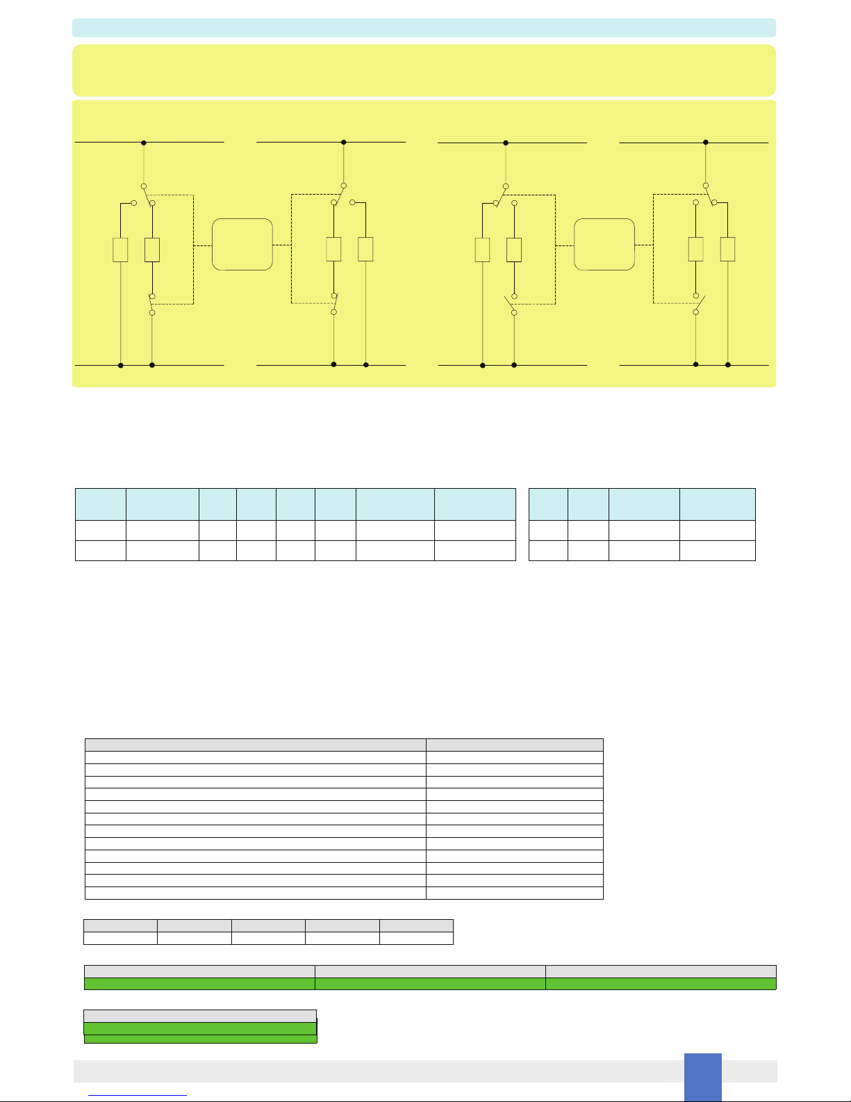
Identify the function and location of each connection terminal using the wiring diagram on the corresponding section, as an example (n° 1 application):
Connect 115 Vac signal lines at input terminals “1” and “2” (input terminals “3” and “4” are provided for daisy chain connection to the next module).
For Load A and its service load:
- connect positive or AC load supply line to terminals “13” and “18”;
- connect SIL 3 Normally Energized (NE) Load between terminals “14” and “16”;
- connect Not SIL Service Load between terminal “17” and negative or AC load supply line;
- connect terminal “15” to negative or AC load supply line.
For Load B and its service load:
- connect positive or AC load supply line to terminals “19” and “24”;
- connect SIL 3 Normally Energized (NE) Load between terminals “23” and “21”;
- connect Not SIL Service Load between terminal “20” and negative or AC load supply line;
- connect terminal “22” to negative or AC load supply line.
Installation and wiring must be in accordance to the relevant national or international installation standards, make sure that conductors are well isolated from each other and
do not produce any unintentional connection.
Connect SPST relay contacts checking the load rating to be within the contact maximum rating (5 A 250 Vac 1250 VA, 5 A 250 Vdc 175 W (resistive load)).
To prevent relay contacts from damaging, connect an external protection (fuse or similar), chosen according to the relay breaking capacity diagram on data sheet.
The enclosure provides, according to EN60529, an IP20 minimum degree of mechanical protection (or similar to NEMA Standard 250 type 1) for indoor installation, outdoor installation
requires an additional enclosure with higher degree of protection (i.e. IP54 to IP65 or NEMA type 12-13) consistent with the effective operating environment of the specific installation.
Units must be protected against dirt, dust, extreme mechanical (e.g. vibration, impact and shock) and thermal stress, and casual contacts.
If enclosure needs to be cleaned use only a cloth lightly moistened by a mixture of detergent in water.
Any penetration of cleaning liquid must be avoided to prevent damage to the unit. Any unauthorized card modification must be avoided.
Relay output contact must be connected to load non exceeding category II overvoltage limits.
Warning: de-energize main power source (turn off power supply voltage) and disconnect plug-in terminal blocks before opening the enclosure to avoid electrical shock
when connected to live hazardous potential.
Start-up
Before powering the inputs of unit check that all wires are properly connected. Check conductors for exposed wires that could touch each other causing dangerous unwanted shorts.
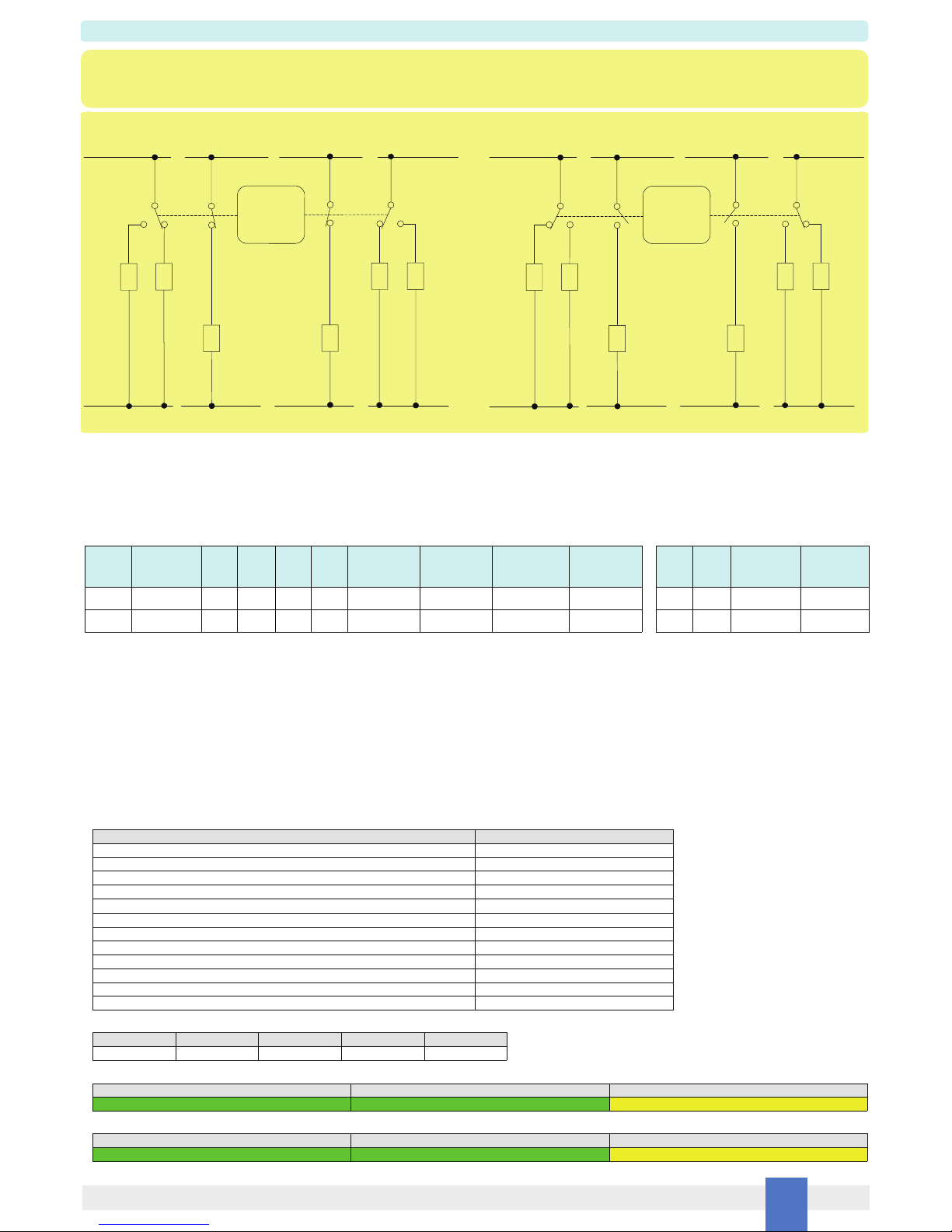
Enabling input, the “RELAY STATUS” yellow led must be lit, all relays must be energized, so that: contacts of terminals “13”-”14” (Out S_1), “15”-”16” (Out S_2), “21”-”22” (Out S_4) and
“23”-”24” (Out S_3) must be closed, while contacts of terminals “17”-”18” (Out P_1) and “19”-”20” (Out P_2) must be open.
Instead, disabling input, the “RELAY STATUS” yellow led must be turned off, all relays must be de-energized, so that: contacts of terminals “13”-”14” (Out S_1),
“15”-”16” (Out S_2), “21”-”22” (Out S_4) and “23”-”24” (Out S_3) must be open, while contacts of terminals “17”-”18” (Out P_1) and “19”-”20” (Out P_2) must be closed.
D5290S-079 is an electrical apparatus installed into standard EN50022 T35 DIN-Rail located in Safe Area / Non Hazardous Location within the specified operating temperature limits
Tamb - 40 to +60 °C. D5290S-079 must be installed, operated and maintained only by qualified personnel, in accordance to the relevant national/international installation standards,
following the established installation rules.
Warning: de-energize main power source (turn off power supply voltage) and disconnect plug-in terminal blocks before opening the enclosure to avoid electrical shock
when connected to live hazardous potential.
Failure to properly installation or use of the equipment may risk to damage the unit or severe personal injury.
The unit cannot be repaired by the end user and must be returned to the manufacturer or his authorized representative.
Any unauthorized modification must be avoided.
The proof test shall be performed to reveal dangerous faults which are undetected by diagnostic. This means that it is necessary to specify how dangerous undetected faults, which
have been noted during the FMEDA, can be detected during proof test. The Proof test consists of the following steps:
Testing procedure at T-proof
Steps Action
1Bypass the safety-related PLC or take other appropriate action to avoid a false trip when removing the unit for test.
2Verify the input-to-output functionality (for a min to max input voltage change 95 to 130 Vac), considering the input signal and each relay output contact state:
□Out S_1 (NO contact) at terminals “13”-“14”: when input is energized, Out S_1 must be closed;
while shutdown of the input channel, Out S_1 must be open;
□Out S_2 (NO contact) at terminals “15”-“16”: when input is energized, Out S_2 must be closed;
while shutdown of the input channel, Out S_2 must be open;
□Out P_1 (2 NC contacts in parallel connection) at terminals “17”-“18”: when input is energized, Out P_1 must be open;
while shutdown of the input channel, Out P_1 must be closed;
□Out S_3 (NO contact) at terminals “23”-“24”: when input is energized, Out S_3 must be closed;
while shutdown of the input channel, Out S_3 must be open;
□Out S_4 (NO contact) at terminals “21”-“22”: when input is energized, Out S_4 must be closed;
while shutdown of the input channel, Out S_4 must be open;
□Out P_2 (2 NC contacts in parallel connection) at terminals “19”-“20”: when input is energized, Out P_2 must be open;
while shutdown of the input channel, Out P_2 must be closed.
3Remove the bypass from the safety-related PLC or restore normal operation inserting the unit.
This test detects almost 100 % of all possible Dangerous Undetected failures in the relay module.
Table of contents
Other GM International Control Unit manuals
Popular Control Unit manuals by other brands

Advntage Controls
Advntage Controls ABC Instructions for use

Lucent Technologies
Lucent Technologies Merlin Magix Configuration note

Progressive Dynamics
Progressive Dynamics PD1201 Installation and operation guide

Schmidt
Schmidt PressControl 3000 Operator's manual

Intel
Intel FM5224 Installation & user guide

Bray
Bray FLOW-TEK Series Installation, operation and maintenance manual

Cavli Wireless
Cavli Wireless C31SS Hardware manual

Avitech
Avitech Sequoia Dual user manual

SICK
SICK CDB620 operating instructions

Vega
Vega VEGAKON 66 operating instructions

Allen-Bradley
Allen-Bradley FLEX Ex 1797-OB4D installation instructions

Pfeiffer Vacuum
Pfeiffer Vacuum TVV 001 operating instructions