GME HG139 User manual

GME
User's Manual
Rev 1.1

TEST INSTRUMENT SAFETY GUIDELINES
WARNING
An electrical shock of over 10 milliamps of current to pass through the heart will stop most human
heartbeats. Voltage as low as 35 volts dc or ac rms should be considered dangerous and hazardous
since it can produce a lethal current under certain conditions. Be sure to observe following safety
precautions:
1. Do not expose high voltage needlessly in the equipment under test. Remove housings and
covers only when necessary. Turn off equipment while making test connections in high-voltage
circuits. Discharge high-voltage capacitors after removing power.
2. If possible, familiarize yourself with the equipment being tested and the location of its high
voltage points. However, remember that high voltage may appear at unexpected points in
defective equipment.
3. Use an insulated floor material or a large, insulated floor mat to stand on, and an insulated work
surface on which to place equipment; make certain such surfaces are not damp or wet.
4. When using a probe, touch only the insulated portion. Never touch the exposed tip portion.
5. When testing ac powered equipment, remember that ac line voltage is usually present on some
power input circuits such as the on-off switch, fuses, power transformer, etc. any time the
equipment is connected to an ac outlet, even if the equipment is turned off.

Limited One-Year Warranty
GME Technology warrants to the original purchaser that this product and the component parts thereof, will be
free from defects in workmanship and materials for a period of one years from the data of purchase. GME
Technology will, without charge, repair or replace, at its’ option, defective product or component parts. Returned
product must be accompanied by proof of the purchase date in the form a sales receipt.
Term and Conditions
•The warranty period is based upon the invoice date of the original purchase by the end-user.
•Warranty only applies to defects in materials and/or workmanship, which occur during normal use.
•Warranty does not apply to those products that are damaged due to misuse, abuse, negligence or
modification.
•Warranty does not extend to any damage that occurs in shipment or due to natural phenomenon (i.e.
lightning or line surges).
•Warranty will be voided if the original serial number on the product is removed by accident or
intentionally
This warranty gives you specific rights and you may have other rights, which vary from state-to-state.
Service & Repair
The following are procedure for returning a GME product for servicing and repair. Turn around time
for repair is normally within five (5) working days excluding shipping time.
RMA Procedure
Before sending your GME product in for service, be sure to contact GME Technology first to
obtain a RMA number. If your product is still under warranty, please send in the product along with a
copy of the receipt showing the date when the product was purchased. If the warranty has already
expired, please ask for the repair cost when you contact GME Technology for the RMA number and
include a check or money order for the repair cost when you send in the product.
Please make check payable to: GME Technology
You may send your GME product to our service & repair department at:
GME Technology
ATTN: Service & Repair Department
380 S. East End Ave., #H
Pomona, CA 91766
Be sure to include a note showing your RMA number, your name, telephone number, return address,
and a description of the problem with the product.
For the most recent support information, please visit GME Technology website at
www.gmetechnology.com/support

Digital TV sales have increased dramatically over the past few years
while the sales of analog sets are declining precipitously. First quarter of
2005 has brought the greatest volume of DTV sales ever recorded, with
2.3 million DTV products accounting for 2.96 billion dollar of consumer
investment. This trend is expected to grow even stronger. With the price
of DTV test equipment stayed relatively expensive, often in the range of
thousands of dollars, the effort of getting into DTV for many individuals
is highly discouraged. The HG139 is designed to accommodate the need
for an affordable high quality tool for the calibration and testing of
digital television.
Table of Contents
Page
Introduction …………………………………………………………………………. 1
Item Checklist ……………….…………………………………………………….... 1
Features ……………………………………………………………………………... 1
Understanding the Front Panel …………………………………………………….... 2
Basic Operation ……………………………………………………………………... 3
Video Patterns and Applications …………………………………………………... 4-10
Specifications ………………….……………………………………………………... 11
GME Product Information …………………………………………………………… 12
Notes ……….………………….…………………………………………………....... 13

www.gmetechnology.com 1
Introduction
Thank you for purchasing the HG139 HDTV (High Definition Television) Pattern Generator. It is an
easy-to-use handheld video pattern generator that generates a wide variety of test patterns for
comprehensive testing, calibration, and repair of HDTV, analog television monitors, and other video
equipments. The HG139 delivers the quality and functionality you would expect from an expensive
high end HDTV pattern generator at a very affordable price. With its easy to understand interface, the
HG139 is designed to meet the need of people from all levels ranging from novice to video
professionals.
The HG139’s clock frequency is 74.25MHz for HDTV modes. The test patterns are generated in real-
time by digital ICs and converted to analog output signal by three precision digital-to-analog
converters. The HG139 generates both a tri-level sync signal for HDTV monitors and a traditional bi-
level sync signal for NTSC monitor. The negative sync pulse amplitude is nominally -0.3 volts below
the blanking level and the positive sync pulse amplitude is nominally +0.3 volts above the blanking
level. Full-scale video/sync is generated in a 7:3 rate, compliant with SMPTE standards signals.
Item Checklist
9One HG139 HDTV pattern generator
9One protective rubber holster
9One 7.5V AC power adaptor
9Three BNC-to-RCA adaptors
9One User’s Manual
Features
♦Designed for testing, calibration, and service of High Definition TV and NTSC analog
television
♦4 selectable modes including 1080i, 720p, 480p, and NTSC
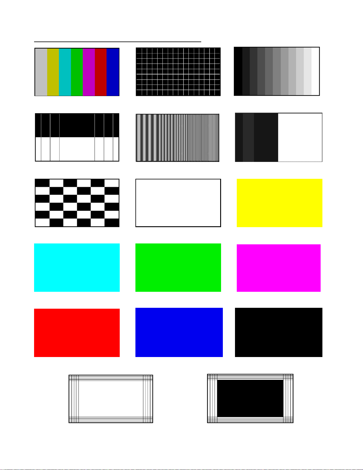
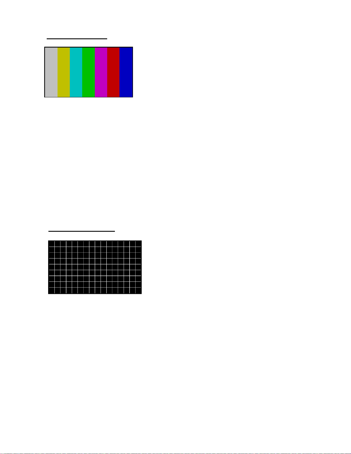
♦9 commonly used video test patterns including COLOR BARS, CROSS HATCH,
STAIRCASE, MULTIBURST, OVERSCAN-BOUNCE, PLUGE, NEEDLE, CHECKER, and
RASTER (choose from White, Yellow, Cyan, Green, Magenta, Red, Blue, and Black)
♦Single push button selectable patterns with hold down reverse
♦Precise 74.25 MHz HDTV clock frequency
♦Conform with SMPTE and NTSC industrial video standards
♦AC adaptor power source or standard 9v battery operation
♦Low battery indicator
♦Handheld enclosure with protective rubber boot
♦Ideal for on-the-bench and in-the-field testing
♦Easy to use, lightweight, portable, and affordable

Understanding the Front Panel
7
1. Power ON/OFF switch
This Power ON/OFF switch is on the left
side of the unit. Slide the switch upward
to turn the unit on and downward to turn
the unit off.
www.gmetechnology.com 2
2. Power ON/OFF LED
Power is ON when the LED lights up and
power is off when the LED is off.
3. Battery Low LED
When the HG139 is operating on a 9V
battery and the voltage on the battery is
drop down to around 5V, this green LED
will turn on indicating the voltage on the
battery is low.
4. 7.5V DC adaptor input
Connect the 7.5V 200mA center
positive AC adaptor (included) to power
the HG139.
5. Video Format selector
Use this selector to choose one of the
following video formats:
1080 30i 720 60p 480 60p NTSC (only luminance signal output for NTSC)
6. Video Pattern button
Use this button to cycle through one of the following video patterns:
COLOR BARS CROSS HATCH STAIRCASE
MULTIBURST OVERSCAN-BOUNCE PLUGE
NEEDLE CHECKER RASTER
NOTE: Holding down this button will display previous patterns in reverse order until COLOR
BARS pattern is reached.
7. YPbPr Video Connectors
These three BNC connectors are labeled Y, Pb, and Pr.
With 1080i, 720p, or 480p mode on the HG139 selected, using BNC cables, connect the three BNC
connectors to the TV’s respective Y, Pb, and Pr component video connectors to output the video
signal to the TV. For TVs that use RCA connectors for component video inputs, use the included
BNC-to-RCA adaptors to connect HG139 to the TV.
With the NTSC mode selected, the video signal will come from the Y connector on the HG139.
Connect the Y output to the TV’s composite video input with a BNC or RCA cable.
24
1
3
5
6

www.gmetechnology.com 3
Basic Operation
1. a: Connect the Y, Pb, and Pr connectors on the HG139 to the HDTV Y, Pb, and Pr
component video inputs respectively. The Y is the luminance signal, and Pb and Pr are the
chrominance (color) signals. The Y signal will drive a 1V peak-to-peak signal into a 75-ohm
load, and the Pb and Pr signals will drive 0.7V peak-to-peak signals into 75-ohm loads.
b: In the case of testing NTSC TV, connect the Y connector on HG139 to the composite
video input on the TV. This connection provides no chrominance, so Color Bars and Raster
will display only luminance with no color. The other patterns will display normally.
2. Using the video format selector, select the appropriate video format on the HG139. Available
video formats include 1080i, 720p, 480p, and NTSC.
3. Slide the power switch to turn on HG139.
4. Use the video pattern button to select the desire video pattern for display. Available video
patterns include COLOR BARS, CROSS HATCH, STAIRCASE, MULTIBURST,
OVERSCAN-BOUNCE , PLUGE, NEEDLE, CHECKER, and RASTER (White, Yellow,
Cyan, Green, Magenta, Red, Blue, and Black).
NOTE: Holding down the video pattern button will display previous patterns in reverse order
until COLOR BARS pattern is reached

Video Patterns and Applications
COLOR BARS CROSS HATCH STAIRCASE
NEEDLE MULTIBURST PLUGE
CHECKER RASTER (White) RASTER (Yellow)
RASTER (Cyan) RASTER (Green) RASTER (Magenta)
RASTER (Red) RASTER (Blue) RASTER (Black)
www.gmetechnology.com 4
OVERSCAN-BOUNCE OVERSCAN-BOUNCE

COLOR BARS
Seven equal width vertical color bars are displayed at 75% amplitude, 100% saturation in the
order from left to right: White, Yellow, Cyan, Green, Magenta, Red, and Blue.
The COLOR BARS video pattern serves as the fundamental pattern used for most testing,
troubleshooting and adjustments in video equipment. Use this test pattern to check and test
the video device’s ability to produce fully saturated primary and secondary colors. It is often
used as the reference for color adjustment and compensation. When troubleshooting, analysis
of the colors bars pattern helps television service personnel to pinpoint color related problem
to specific circuits. This pattern can also be use as a reference for troubleshooting color
amplifier or color demodulator problems inside the display device.
CROSS HATCH
This pattern displays a series of horizontal and vertical straight white lines that forms a grid
of 16 x 9 squares of the same size for 1080i and 720p, 12 x 9 squares for 480p and NTSC.
This pattern used to check and adjust dynamic convergence of the display. Observe the
horizontal and vertical lines to detect color fringing resulting from misconvergence. An
example that the display is misconverged is when the white lines become separated Red,
Green, and Blue lines. Adjust the display’s RGB convergence control to align the colors to
overlap so the horizontal and vertical lines appear as white lines.
This pattern can also be provides a convenience reference for making vertical and horizontal
linearity adjustments. Each square should be the same size.
CROSS HATCH pattern is also useful for checking pincushion (bow) distortion and display
geometry such as picture centering, size, and trapezoid (keystone) correction. For trapezoid
correction, adjust the TV’s display control so that the pattern’s edges are parallel to the edges
of the display screen. For pincushion correction, the horizontal and vertical lines should be
adjusted to be straight.
www.gmetechnology.com 5

STAIRCASE
The STAIRCASE pattern displays equal-width vertical bar steps of increasing luminance
from left to right.
This pattern is useful in checking amplifier linearity. The increment of amplitude from one
step to the next should be equal. Non-equal steps represent non-linear distortion. Typical
luminance nonlinear distortions will result in a loss of grey-scale distinctions, which means
that detail is loss.
Each of the vertical bars should have distinctive brightness level. The display is too dark
when the black vertical bars blend together. The display is too bright when the white vertical
bars blend together. Adjust the display cutoff/bias controls and drive/gain controls so each
vertical bar has distinctive brightness level.
This pattern is also useful for checking and adjusting the grayscale performance of a video
device. This pattern is seen as a primary color (red, green, or blue) tint on display device with
poor grayscale performance.
MULTIBURST
The MULTIBURST pattern displays five frequency bands of progressively higher frequency
from left to right. The following frequencies are displayed: 2.32MHz, 4.64MHz, 6.19MHz,
9.28MHz, and 18.56MHz for 1080i / 720p formats; 1.16MHz, 2.32MHz, 3.09MHz,
4.64MHz, and 6.19MHz for 480p; 1.16MHz, 1.55MHz, 2.32MHz, 4.64MHz for NTSC
format.
This pattern is useful for measuring video equipment’s resolution and video bandwidth. Each
band consists of a series of alternating black and white vertical lines. The lines become closer
as bands of higher frequency are displayed. The resolution of the equipment being tested can
be determined by the maximum frequency at which individual lines can be discerned. Use
this pattern to check a display device’s capability to produce sharply defined alternating black
and white stripes up to the format’s full resolution.
Depending on a device’s ability to handle high frequency signals, some display devices with
insufficient high frequency response will display this pattern with black and white stripes
blurred together for the higher frequency bands.
www.gmetechnology.com 6

OVERSCAN-BOUNCE.
www.gmetechnology.com 7
The Overscan-Bounce pattern consists of 4 horizontal lines on the top and bottom edge of the
screen and 4 vertical lines at the left and right edge of the screen. These lines mark 2.5%, 5%,
7.5%, and 10% of the width and height of the screen. The background of the screen alternates
between black and white.
This pattern is useful for checking the amount of overscan of a display monitor. The 4 lines at
each of the four edges are helpful in determining whether there is equal amount of overscan
at the sides or at the top and bottom of the screen. Adjust the display device’s geometry
controls to obtain the desire amount of overscan or underscan.
The Overscan-Bounce pattern is also useful for checking pincushion (bow) distortion and
display geometry such as picture centering, size, and trapezoid (keystone) correction and
linearity. For trapezoid correction, adjust the TV’s display control so that the pattern’s edges
are parallel to the edges of the display screen. For pincushion correction, the horizontal and
vertical lines should be adjusted to be straight.
It is also used to check the stability of the high-voltage and deflection power supply circuits.
The Overscan Bounce pattern changes repeatedly from a low to high APL (average picture
level). As the picture APL changes, the picture size may momentarily expand and contract.
The amount of change can be measured by the shift of the lines on the screen edges.

PLUGE
www.gmetechnology.com 8
0 +5 0/-5 0 +50
The PLUGE (stands for Picture Line-Up Generation Equipment) pattern is divided into two
halves.
The left half consists of 2 vertical stripes against a black background, i.e. 7.5 IRE for NTSC
and 0 IRE for the other patterns. The left stripe is fixed at a brightness level slightly whiter
than black (12.5 IRE for NTSC and 5 IRE for the other video formats). The right stripe
alternates between black and slightly blacker than black (7.5/2.5 IRE for NTSC, 0/-5 IRE for
the other video formats).
The right half of the pattern is fix at 57.5 IRE for NTSC and 50 IRE for the other formats.
Note: the IRE values for NTSC is different from the other formats by 7.5 IRE due to the 7.5
IRE setup for the NTSC format.
The PLUGE pattern is used to calibrate the black level on a display device. Black level
basically refers to the brightness of the darkest areas in the picture. Adjust the appropriate
controls on the display device (i.e. brightness and contrast controls, etc.) to calibrate the black
level on the device. Refer to the following when making calibration:
♦The left vertical stripe is just visible as a dark gray.
♦The right vertical stripe alternates between black and slightly blacker so should not be
visible against the background. If blinking can be seen on this vertical stripe, it means
the brightness of the display is set too high. Lower the brightness level until the
blinking barely disappears.
♦The right half of the pattern is a lighter gray and should be clearly visible.
This pattern is also useful for checking DC restoration (black clamping) performance of a
display device. If a display device has good DC restoration, its black level control can be
adjusted on either a low API (average picture level) or high APL pattern, with no change in
black level as you switch from one pattern to another. Display device with less than perfect
DC restoration will exhibit alternating changes of brightness in the black background and the
+10 IRE vertical stripe. This is due to the display device’s inability to perfectly clamp black
to a fixed level. This can be determined when the brightness level is adjusted slightly above
normal setting. If the brightness level of the two vertical stripes remains constant as the right
stripe blinks (alternating between black and slightly blacker than black), the display has good
DC restoration.

NEEDLE
The NEEDLE pattern is symmetrically divided into top half and bottom half. The top half has
black background with white vertical needle pulse lines and the bottom half has white
background with black vertical needle pulse lines.
The width of the vertical line should remain constant as it transitions between white and
black. This pattern is useful for detecting whether scan velocity modulation (SVM) is enabled
on the display monitor. SVM tends to introduce horizontal nonlinearity in the image, causing
the black lines on the bottom of the pattern to be thicker than the white lines on the top of the
pattern.
The NEEDLE pattern also works very well for adjusting the contrast control for maximum
light level while minimizing raster distortion or blooming. Blooming results in light from
very bright pixels spilling over to adjacent pixels. This causes bright picture areas to become
defocused and slightly larger than they should be. Raster distortion at high luminance level is
caused by high voltage power supply regulation problems. The vertical needle pulses should
be straight without any bowing. If the contrast is set too high, the display’s power supply may
cause raster distortion, visible as bending in the needle pulses. For the least picture distortion,
adjust the contrast to a setting just below where either blooming or raster distortion becomes
visible. This may sometimes result in a picture with unacceptably low white level. In this
case, a compromise needed to be made between an accurate display and a brighter display.
www.gmetechnology.com 9

CHECKER
The CHECKER pattern displays alternating black and white boxes as in a checker board.
This pattern is useful in checking the high voltage regulation of CRT power supply circuits.
Poor regulation results in trapezoidal looking pattern. For CRT type monitors with
insufficient power supply regulation can result in the corners of each box do not touch each
other as they should. This effect can sometimes be reduced by lowering the brightness or
contrast settings.
This pattern is also useful for checking ringing of the video signal as the signal transitions
from black to white. The abrupt, maximum change in CRT video drive current produced by
this pattern should not cause the voltage supplied to the video drive circuit to change in
display device with good voltage regulation. For display device with power supply that does
not have good regulation, softening or ringing in the pattern transitions can result.
RASTER
The RASTER patterns consist of 8 full field color patterns at 75% amplitude. The colors
displayed are: White, Yellow, Cyan, Green, Magenta, Red, Blue, and Black.
RASTER patterns are useful for checking color purity and uniformity. Color purity problems
are often caused by the magnetization of some parts inside a CRT display device. This often
results in areas of color on the white raster pattern. Use the three primary color raster patterns
(Red, Green, and Blue) to check for missing and defective pixels on a LCD monitor. Missing
and defective pixels are common problems on this type of display devices.
The Red, Green, and Blue raster patterns are valuable for adjusting the three separate guns
that generate these three primary colors inside a display monitor. A full field display of each
of the eight individual color RASTER patterns also simplifies the analysis of hue and
saturation problems.
www.gmetechnology.com 10

www.gmetechnology.com 11
Specifications
Video Modes 1920 x 1080 30i
1280 x 720 60p
720 x 480 60p
NTSC (luminance only)
Video Patterns COLOR BARS
CROSS HATCH
STAIRCASE
MULTIBURST
OVERSCAN-BOUNCE
PLUGE
NEEDLE
CHECKER
RASTER
Y output Output impedance: 75Ω
1 Vp-p into 75Ω
Pb output Output impedance: 75Ω
0.7 Vp-p into 75Ω
Pr output Output impedance: 75Ω
0.7 Vp-p into 75Ω
Clock Frequency 74.25 MHz
Power 7.5V center-positive AC adaptor or 9V battery
Dimension 5.7"(H) x 3.3"(W) x 1.5"(D) (w/o rubber holster)
Weight 0.8 lb

WWW.GMETechnology.COM
For product updates and information
CHECK OUT THESE OTHER TEST EQUIPMENT
AVAILABLE FROM GME
GME offers many different types of electronic test equipment to suit your needs. Here are some of the
test equipment products we offer.
Model Description
HG139 HDTV Pattern Generator
SG-10 10 MHz DDS Signal Generator
236 In-Circuit ESR & DCR Capacitor Tester
PG-16A NTSC & Monitor Tester (Handheld Model)
PG-68 NTSC & Monitor Tester (Benchtop Model)
PG-38 NTSC Pattern Generator
MT-160 Computer Monitor Tester
LC200 Digital LC Meter
C350 Capacitance Meter
Other products such as digital / analog panel meters, step motor drivers are also available. Please visit
our website at www.gmetechnology.com for complete detail.
www.gmetechnology.com 12

www.gmetechnology.com 13
Notes

GME Technology
380 S. East End Ave. #H
Pomona, CA 91766
TEL: 909-865-1998
FAX: 909-865-2793
www.gmetechnology.com
Table of contents
Other GME Test Equipment manuals