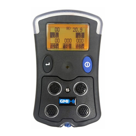
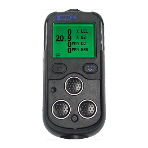
GMI PS200 series User manual

Personal Surveyor 200
Auto Bump / Calibration
Station - Handbook
Gas Measurement Instruments Ltd

i
LICENCE AGREEMENT
This Licence Agreement is your proof of licence. Please treat it as valuable
property. Please note that this licence agreement supersedes the “statement of
Copyright Restrictions”.
IMPORTANT - READ CAREFULLY
This is a legal and binding contract between you (either an individual or an entity),
the end user and Gas Measurement Instruments Limited (GMI). By opening
sealed software packages or by installing, copying, or otherwise using this ‘PS200
Settings’ Auto Bump / Cal Station application program (“SOFTWARE”), you agree
to be bound by the terms of this agreement. If you do not agree to the terms of
this agreement you should promptly return this disc package and accompanying
items* (including written materials, binders or containers) to GMI.
CALIBRATION SOFTWARE LICENCE
1. GRANT OF LICENCE: The ‘PS200 Settings’ Licence Agreement (Licence)
permits concurrent use of the SOFTWARE on the number of computers for which
this licence grants (that is: single user package licences one user; twenty user
package licences twenty users). Additional SOFTWARE licences may be purchased
for each additional concurrent user.
If you have acquired this SOFTWARE in a multiple licence pack, you may make
the number of additional copies of the SOFTWARE authorised on the printed copy
of the licence. You may also store or install a copy of the network SOFTWARE
on a storage device, such as a network server, used only to install or run the
SOFTWARE on your other computers over an internal network; however you
must acquire and dedicate a licence for each separate computer on which the
SOFTWARE is installed or run from the storage device. A licence for the software
may not be shared or used concurrently on different computers.
This licence is granted for use on the GMI products and for use on one computer.
If you require a second copy you must purchase that from GMI or its distributor.
The documentation accompanying this software is essential for the correct and
safe operation of the instruments.
This software is used on certied equipment which may be used in life critical
applications. Only trained competent personnel should use this equipment and
should be aware of the certication, calibration and Health and Safety issues
associated with the product and its application.
2. COPYRIGHT: The SOFTWARE is owned by GMI and is protected by United
Kingdom copyright laws and international treaty provisions. Therefore you must
treat the SOFTWARE like any other copyrighted material (for example, a book or
musical recording) except that you may either (a) make one copy of the SOFTWARE
solely for backup or archival purposes, or (b) transfer the SOFTWARE to a single

ii
AUTO BUMP / CAL STATION - HANDBOOK
hard disk provided you keep the original solely for backup and archival purposes.
You may not copy the written materials accompanying the SOFTWARE.
3. OTHER RESTRICTIONS: You may not rent or lease the SOFTWARE, but
you may transfer the SOFTWARE and accompanying written materials on a
permanent basis to another individual. If you transfer the software, you must
retain no copies and the recipient must agree to the terms of this agreement.
You must not reverse engineer, decompile, or disassemble the SOFTWARE that
is provided solely as executable programs (.EXE les) or dynamic link libraries
(.DLL les). If the SOFTWARE is an update, any transfer must include the update
and all prior versions.
30 DAY LIMITED WARRANTY
If the product was purchased in the UK , simply return the full product in resaleable
condition* within 60 days of purchase to GMI, together with your original receipt or
invoice, for a full refund. If this product was not purchased in the UK, you should
return the full product* to the place of purchase within 30 days of purchase for
a full refund.
LIMITED WARRANTY
The CD-ROM and Handbook that make up this software product are warranted
by GMI to be free from defects in materials and workmanship for a period of 60
(sixty) days from the date you purchased this product. If you notify GMI within the
warranty period of such defects in materials or workmanship, GMI will replace
the defective CD-ROM or handbook. The sole remedy for breach of this warranty
is limited to replacement of defective CD-ROM and handbook and / or refund of
purchase price and does not include any other kinds of damage. Apart from the
foregoing limited warranty, the software programs are provided “AS IS”, without
warranty of any kind, either expressed or implied. The entire risk as to the
performance of the program is with the purchaser. GMI does not warrant that the
operation of the programs will be uninterrupted or error free. GMI assumes no
responsibility or liability of any kind for errors in the program or documentation or
for the consequences of any such errors.
INCIDENTAL AND CONSEQUENTIAL DAMAGES CAUSED BY MALFUNCTION,
DEFAULT, OR OTHERWISE WITH RESPECT TO BREACH OF THIS WARRANTY
OR ANY OTHER EXPRESS OR IMPLIED WARRANTIES, INCLUDING THOSE
OF MERCHANTABILITY AND FITNESS FOR A PARTICULAR PURPOSE, ARE
NOT THE RESPONSIBILITY OF GMI AND ARE HEREBY EXCLUDED BOTH
FOR PROPERTY AND, TO THE EXTENT NOT UNCONSCIONABLE, FOR
PERSONAL INJURY DAMAGE.
The remedies described above are the exclusive remedies extended to you by GMI
for any default, malfunction or failure of the product to conform with this warranty or
otherwise for the breach of this warranty or any other warranty, whether expressed
or implied. Should you have any questions concerning this agreement please
contact the GMI sales department on +44 (0)141 812 3211.
* If the product is not in resaleable condition, you will be charged a 20% restocking
fee.
iii
COPYRIGHT
COPYRIGHT
This document is copyright of GMI and the information contained within is for use
only with ‘PS200 Settings’ Software. Reproduction, in whole or in part, including
utilisation in machines capable of reproduction or retrieval without the written
permission of GMI is prohibited. Reverse engineering is not permitted.
TRADEMARK INFORMATION
Windows XP™, Vista™ and 7™ are registered trademarks or trademarks of the
Microsoft Corporation in the United States and / or other countries.
LIABILITY
Every care has been taken in the preparation of this document, however, GMI
do not accept any responsibility for errors or omissions and their consequences.
Information in this document is subject to change without prior notice.
This document does not constitute a specication or basis for a contract.
Your statutory rights under UK law are not affected.

iv
AUTO BUMP / CAL STATION - HANDBOOK

v
TABLE OF CONTENTS
LICENCE AGREEMENT i
IMPORTANT - READ CAREFULLY i
CALIBRATION Software Licence i
30 DAY LIMITED WARRANTY ii
LIMITED WARRANTY ii
COPYRIGHT iii
TRADEMARK INFORMATION iii
LIABILITY iii
INTRODUCTION 1-1
1.1 GENERAL DESCRIPTION 1-1
1.2 AUTO BUMP / CALIBRATION HARDWARE
(6mm ttings) 1-4
1.3 AUTO BUMP / CALIBRATION HARDWARE
(1/4 in. ttings) 1-5
1.4 ADDITIONAL ACCESSORIES 1-5

vi
AUTO BUMP / CAL STATION - HANDBOOK
CONNECT CALIBRATION GAS & POWER SUPPLY
2-1
2.1 CONNECT CALIBRATION GAS 2-1
2.1.1 Compare Gas Cylinder Label with Software
Conguration 2-2
2.1.2 Connect Gas Cylinder to Auto Bump / Cal
Station 2-4
2.1.3 Connect Air / Exhaust Tubing to Auto Bump /
Cal Station (if required) 2-6
2.2 CONNECT POWER SUPPLY 2-8
VIEW / RE-CONFIGURE SOFTWARE 3-1
3.1 VIEW / EDIT SOFTWARE CONFIGURATION 3-1
3.1.1 Quick Bump Test 3-5
3.1.2 Full Bump Test (Factory Default) 3-6
3.1.3 Calibration 3-10
3.1.4 Generate Settings File 3-14
3.2 TRANSFER UPDATED ‘PS200 SETTINGS’
SOFTWARE to AUTO BUMP / CAL STATION 3-15
INSTALL INSTRUMENT IN STATION & PERFORM
BUMP / CALIBRATION 4-1
4.1 INSTALL INSTRUMENT in AUTO BUMP / CAL
STATION 4-1
4.2 PERFORM BUMP / CALIBRATION 4-6

vii
CONTENTS
4.3 REMOVE INSTRUMENT from AUTO BUMP / CAL
STATION 4-11
4.4 AUTO BUMP / CAL STATION FAULT INDICATION
4-13
VIEW / PRINT TEST RESULTS 5-1
5.1 INTRODUCTION 5-1
5.2 DOWNLOAD TEST RESULTS 5-2
5.3 VIEW / PRINT TEST RESULTS 5-4
Test Results: 5-6
Generated Certicates: 5-11
Certicate Content: 5-12
Include Company Logo: 5-13
Generated Certicate Files: 5-14
FIT MOUNTING BRACKET A-1
1.1 GENERAL DESCRIPTION A-1
1.2 FIT MOUNTING BRACKET A-2
1.3 ATTACH STATION to WORKBENCH / DAISY CHAIN
OPTION A-3
INDEX i

viii
AUTO BUMP / CAL STATION - HANDBOOK

1-1
1
INTRODUCTION
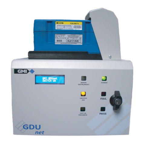
Fig. 1-1 PS200 Series Auto Bump / Calibration Station
1.1 GENERAL DESCRIPTION
The GMI Personal Surveyor 200 (PS200) Series Auto Bump
/ Calibration Station provides the user with a quick, easy and
reliable method of ensuring that PS200 series instruments are
correctly calibrated where company policy dictates. Equipment
does not have to be taken out of service for extended time
periods while testing is undertaken.

1-2
AUTO BUMP / CAL STATION - HANDBOOK
The Auto Bump / Calibration Station can be used for:
• A ‘Quick’ Bump Test, approximately 15 seconds gas
duration, to verify that the instrument alarms will activate
when the alarm setpoints are reached.
• A ‘Full’ Bump Test (factory default), approximately 60
seconds gas duration, performs a full Bump Test of alarm
setpoints and sensor response. This is followed up with
an automatic calibration of failed gas ranges, if applicable.
• A Full Calibration of the instrument, approximately 60
seconds gas duration.
The unit can be free standing on a workbench, or alternatively,
secured to the workbench individually or in daisy chain fashion
using the mounting bracket and screws supplied with the unit.
Refer to APPENDIX-A for tting instructions.
Power is supplied to the rear of the unit via a 12V Universal
Power Supply Unit (PSU) supplied with the unit. A 12V Vehicle
Power Supply is available as an accessory.
Gas is connected to the clearly marked inlet adaptor at the
rear of the unit. An integral pump automatically draws gas into
the instrument for bump / calibration operation.
The user simply inserts the PS200 instrument to be tested
into the Auto Bump / Calibration Station, then closes the cover
initiating the automatic testing process.
The Auto Bump / Calibration Station uses a trafc light system
to display progress / result and thus provides the user with
a clear indication of whether the PS200 meets selected
parameters.
i.e. LED 1 (Green) = ON (power)
LED 2 (Orange) = TEST (in progress)
LED 3 (Green) = PASS
LED 4 (Red) = FAIL

1-3
INTRODUCTION
Note: The ‘PASS’ or ‘FAIL’ LED’s indicate the overall result. If
any doubt exists about the obtained result, please contact GMI.
GMI ‘PS200 Settings’ Software is a Windows™ based ‘stand
alone’ application that allows the user to edit test parameters
and view and / or print test results.
This software will run on any PC / Laptop with Windows XP™,
Windows Vista™, or Windows 7™ (32bit or 64bit) software
installed (Net Framework 2.0 or higher may also be required
on early Windows XP™ operating systems).
Both the Auto Bump / Calibration Station and the USB memory
stick are supplied from GMI with necessary ‘PS200 Settings’
software installed. This pre-installed software is congured
to factory default parameters as detailed in the following
chapters. The software conguration parameters can be
edited via PC or Laptop then the settings le transferred to
the Auto Bump / Calibration Station using the USB memory
stick supplied.
The software provides a full audit trail of tested instruments
and the resulting data is retained in the station memory until
downloaded to the USB memory stick, supplied by GMI, before
being transferred to any compatible PC / Laptop for long term
storage, review, and / or printing. The instrument ‘Cal Due’
date is also updated on successful completion of calibration.
A Calibration Certicate can also be generated automatically
after successful completion of instrument testing.
A permanent PC connection is provided via mini-USB socket
at the rear of the Auto Bump / Calibration Station. An Ethernet
socket is also provided at the rear of the unit to allow results
to be gathered over a network. Both of these options require
‘exiCal Plus’ software package, available from GMI.

1-4
AUTO BUMP / CAL STATION - HANDBOOK
Note: PS200 Bump / Calibration Software is only one part of
the requirement in terms of calibration and maintenance of
a PS200 portable gas detector. Gases, delivery and trained
personnel are all of equal or even greater importance.
The Auto Bump / Calibration Station can also be used to
charge the instrument while power supply is connected. This is
indicated as a ashing battery symbol and ‘CHARGING’
on the instrument display. Charging will take up to 4 hours
to complete. On completion, a full battery symbol and
‘CHARGING COMPLETE’ is displayed.
The instrument will not be damaged if left in Auto Bump /
Calibration Station after charging.
1.2 AUTO BUMP / CALIBRATION HARDWARE
(6mm ttings)
• The Auto Bump / Calibration Station (GMI Part No.
64052) includes 12V output Universal Power Supply
Unit (PSU), and USB Memory Stick with GMI ‘PS200
Settings’ software pre-installed.
• A Test Gas Kit (GMI Part No. 64060) is available as an
accessory and is supplied complete with Combi Test Gas
Cylinder (containing a mixture of 2.5% CH4, 500ppm CO,
50ppm H2S, 18% O2and balance N2), On Demand Gas
Flow Regulator and Tubing.

1-5
INTRODUCTION
1.3 AUTO BUMP / CALIBRATION HARDWARE
(1/4 in. ttings)
• The Auto Bump / Calibration Station (GMI Part No.
64052Q) includes Adaptor Kit, 12V output Universal
Power Supply Unit (PSU), and USB Memory Stick with
GMI ‘PS200 Settings’ software pre-installed.
• A Test Gas Kit (GMI Part No. 64060) is available as an
accessory and is supplied complete with Combi Test Gas
Cylinder (containing a mixture of 2.5% CH4, 500ppm CO,
50ppm H2S, 18% O2and balance N2), On Demand Gas
Flow Regulator and Tubing.
1.4 ADDITIONAL ACCESSORIES
• Combi Test Gas Cylinder (GMI Part No. 99146) containing
a mixture of 2.5% CH4, 500ppm CO, 50ppm H2S, 18%
O2and balance N2. This cylinder is supplied in Test Gas
Kit(s) above.
• On Demand Gas Flow Regulator (GMI Part No. 99118).
This regulator is supplied in Test Gas Kit(s) above.
• 1.0 metre Tygon®tubing complete with 6mm adaptor
(GMI Part No. 64265).
• Adaptor Kit (GMI Part No. 67305) 6mm to 1/4in. adaptor
x 3.

1-6
AUTO BUMP / CAL STATION - HANDBOOK

2-1
2
CONNECT CALIBRATION GAS & POWER SUPPLY
2.1 CONNECT CALIBRATION GAS
Gas is supplied to the Auto Bump / Calibration Station from
the Combi Test Gas Cylinder (GMI Part No. 99146) via an On
Demand Flow Regulator (GMI Part No. 99118) and Tygon®
tubing complete with adaptor (GMI Part No. 64265).
Fig. 2-1 Calibration Gas Setup
The above three items are available as a Test Gas Kit
(GMI Part No. 64060).

2-2
AUTO BUMP / CAL STATION - HANDBOOK
2.1.1 Compare Gas Cylinder Label with Software
Conguration
First of all, make sure that the cylinder is not older than the
‘use by’ date on the label illustrated in Fig. 2-2.
Make sure that the cylinder contains enough gas to complete
the bump test / calibration. The pressure gauge on the
Regulator Valve, after tting, gives a clear indication of this.
When applying gas to the instrument via the Auto Bump /
Cal Station, it is important that the gas concentrations listed
on the cylinder label are consistent with the current software
conguration downloaded from the USB memory stick to the
Auto Bump / Cal Station.
As illustrated in Fig. 2-2, the cylinder gas concentrations can
be easily found on the cylinder label.
Fig. 2-2 Gas Cylinder Label

2-3
CONNECT CALIBRATION GAS AND POWER SUPPLY
The concentrations, illustrated in Fig. 2-2, should be consistent
with Auto Bump / Cal Station installed software conguration
window, as illustrated in Fig. 2-3.
Software
Configuration
Gas Concentr
ations
Fig. 2-3 Software Conguration
After comparing gas values between Cylinder Gas Label and
Software Conguration, when consistent, proceed to next
paragraph.
If inconsistent, refer to Chapter 3 to update software
conguration then download updated conguration to Auto
Bump / Calibration Station.

2-4
AUTO BUMP / CAL STATION - HANDBOOK
2.1.2 Connect Gas Cylinder to Auto Bump / Cal Station
Connect the On Demand Regulator Valve to the gas cylinder
by screwing the valve rmly into the top of the cylinder, as
illustrated in Fig. 2-4. Fitting is simplied by pressing the valve
on to the cylinder with one hand and turning the cylinder with
the other. Care must be taken not to over-tighten the valve.
Fig. 2-4 Attach Regulator Valve to Gas Cylinder
Connect the barbed adaptor, supplied with the station, to the
other end of the tubing, then push the adaptor into the ‘GAS’
inlet adaptor tting on the rear of the Auto Bump / Cal Station,
as illustrated in Fig. 2-5.
Note: 6mm o/d tubing (not supplied), connects directly into
the ‘GAS’ inlet adaptor tting on the rear of the station.
Other manuals for PS200 series
4
This manual suits for next models
2
Table of contents
Other GMI Measuring Instrument manuals

GMI
GMI V!SA Instruction Manual

GMI
GMI PS200 series User manual

GMI
GMI PS1 Instruction Manual

GMI
GMI Gasurveyor 6 - 500 Instruction Manual

GMI
GMI Gasurveyor 500 Series Installation guide

GMI
GMI GT series Instruction Manual

GMI
GMI GT series User manual

GMI
GMI PS200 series User guide

GMI
GMI PS200 series Instruction Manual

GMI
GMI GT series Instruction Manual