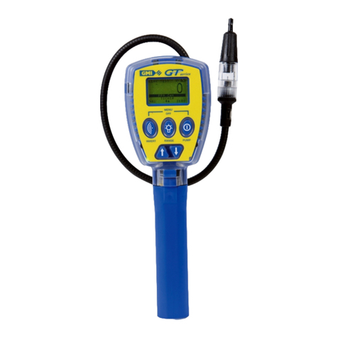
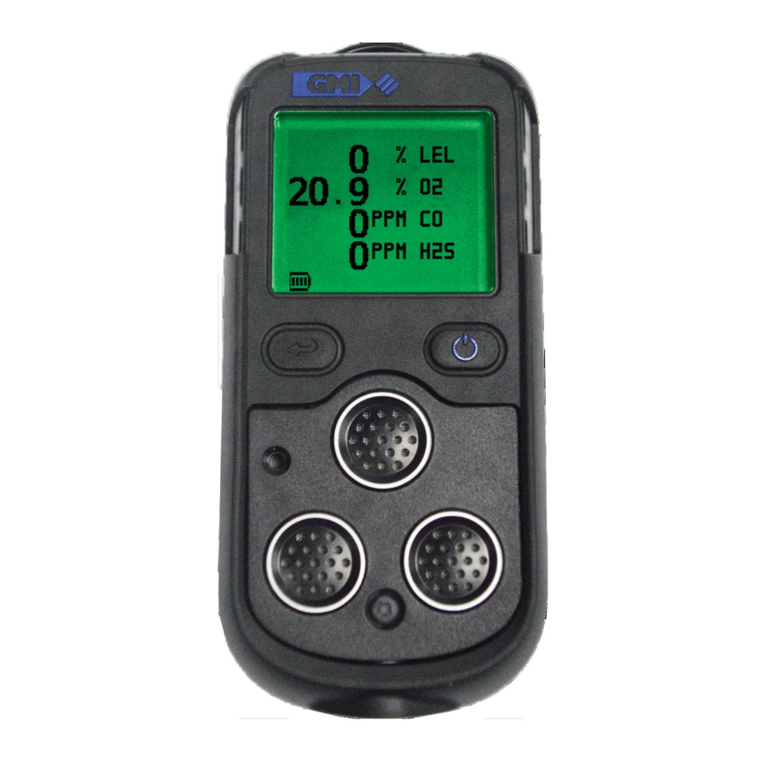
GMI GT series Instruction Manual

User Handbook
Gas Measurement Instruments Ltd

USER HANDBOOK
Issue 9
08/01/2016
Part Number: 67112
GMI welcomes comments on all our publications.
Your comments can be of great value in helping us to improve
our customer publications. Please send any comments that you
Copyright ©Gas Measurement Instruments Ltd 2005

i
COPYRIGHTUSER HANDBOOK
COPYRIGHT
This User Handbook is copyright of Gas Measurement Instruments Ltd (GMI) and
the information contained within, is for use only with
GT series
instruments.
Reproduction, in whole or in part, including utilisation in machines capable of
reproduction or retrieval without written permission of GMI is prohibited. Reverse
engineering is not permitted.
LIABILITY
Every care has been taken in the preparation of this document, but GMI do
not accept any responsibility for errors or omissions and their consequences.
Information in this document is subject to change without notice. This document
does not constitute a specication or basis for a contract. Your statutory rights
under law are not affected.
MODIFICATION NOTICES
GMI aim to notify customers of relevant changes in the product operation and
maintain this manual up to date. In view of the policy of continuous product
improvement there may be operational differences between the latest product
and this manual.
This Handbook is an important part of the
GT series
product. Please note
the following points:
• It should be kept with the instrument for the life of the product.
• Amendments should be attached.
• This Handbook should be passed on to any subsequent owner/user of
the instrument.
• Although every care is taken in the preparation of this Handbook it does
not constitute a specication for the instrument.
SOFTWARE
Software supplied on EPROM or similar device for use in a particular product,
may only be used in that product and may not be copied without the written
permission of GMI. Reproduction or disassembly of such embodied programmes
or algorithms is prohibited. Ownership of such software is not transferable and
GMI does not warrant that the operation of the software will be error free or that
the software will meet the customer’s requirements.
DISPOSAL ADVICE
When no longer in use, dispose of the instrument carefully and with respect for
the environment. GMI will dispose of the instrument without charge if returned
to the factory.

ii
COPYRIGHTUSER HANDBOOK
SAFETY
• The instrument must be regularly serviced and calibrated by fully trained
personnel in a safe area.
• Batteries: Alkaline or *Rechargeable batteries must be exchanged
(*and recharged) in a safe area and tted correctly before use.
Never use damaged batteries or expose to extreme heat.
See Chapter 13 : OPERATOR MAINTENANCE.
• Only GMI replacement parts should be used.
• If the instrument detects gas, follow your own organisation’s procedures
and operational guidelines.
• The combustion chamber is a ameproof assembly and must not be
opened in the presence of a ammable atmosphere.
•
GT series
instruments are certied as:
SIRA 05ATEX II 2 G EEx iad IIB T3
UL 913 Class I, Div 1 Groups C and D.
• This equipment is designed and manufactured to protect against other
hazards as dened in paragraph 1.2.7 of Annex II of the ATEX Directive
94/9/EC.
Any right of claim relating to product liability or consequential damage to any
third party against GMI is removed if the warnings are not observed.
WARNING: To prevent ignition of ammable or combustible atmospheres,
remove batteries before servicing.
WARNING: To prevent ignition of ammable or combustible atmospheres, read,
understand and adhere to the manufacturer’s live maintenance procedures.
WARNING: To reduce the risk of ignition of a ammable or explosive atmosphere,
batteries must be changed only in a location known to be non-hazardous.
WARNING: To reduce the risk of explosion, do not mix old batteries with used
batteries or mix batteries from different manufacturers.
WARNING: Never attempt to recharge non rechargeable cells.
CAUTION: Not for use in oxygen enriched atmospheres.
CAUTION: Replace instrument batteries only with approved batteries, as follows:
ATEX / IECEx APPROVED INSTRUMENTS:
• See ‘SPECIAL CONDITIONS FOR SAFE USE’ on the following page.
UL APPROVED INSTRUMENTS:
• Alkaline: Any ‘LR14’ type
• Rechargeable NiMH: Any ‘C’ type

iii
COPYRIGHTUSER HANDBOOK
SPECIAL CONDITIONS FOR SAFE USE
Note: For ATEX / IECEx approved instruments only.
1. When the batteries are replaced, only the following non-rechargeable
cells are permitted:
Energizer No. E93, Alkaline, (Zn/MnO2), LR14 Size ‘C’ cell
Duracell Procell, Alkaline, (Zn/MnO2), LR14 Size ‘C’ cell
Duracell Plus, Alkaline, (Zn/MnO2), LR14 Size ‘C’ cell
Duracell, Alkaline, (Zn/MnO2), LR14 Size ‘C’ cell
2. When the batteries are replaced, only the following rechargeable cells
are permitted:
Panasonic 3000mAh Sub-C size, Nickel Metal Hydride cells type
HHR300SCP
AREAS OF USE
Exposure to certain chemicals can result in a loss of sensitivity of the ammable
sensor. Where such environments are known or suspected it is recommended
that more frequent response checks are carried out. The chemical compounds
that can cause loss of sensitivity include Silicones, Lead, Halogens and Sulphur.
Do not use instrument in potentially hazardous atmospheres containing greater
than 21% Oxygen. Do not use in areas where explosive concentrations of
Hydrogen may be present. The enclosure material is polypropylene and must not
be exposed to environments which are liable to result in mechanical or thermal
degradation or to damage caused by contact with aggressive substances.
Additional protection may be required in environments where the instrument
enclosure is liable to damage.
STORAGE, HANDLING AND TRANSIT
Rechargeable batteries contain considerable energy and care should be taken
in their handling and disposal. Batteries should be removed if the instrument
is stored for longer than 3 months. The instrument is designed to handle harsh
environments. The instrument is sealed to IP54. If not subject to misuse or
malicious damage, the instrument will provide many years of reliable service.
The instrument contains electrochemical sensors with a life of 2 years. Under
conditions of prolonged storage the sensors should be removed. The sensor
contains potentially corrosive liquid and care should be taken when handling or
disposing of the sensor, particularly when a leak is suspected.
WARRANTY
The
GT series
instrument has a warranty against faulty goods or workmanship
of 5 years. Consumable and mechanical parts are not included in this. These
are covered under GMI standard warranty conditions. For details, please
contact GMI Ltd (UK).

iv
COPYRIGHTUSER HANDBOOK

v
CONTENTS
COPYRIGHT............................................................................ i
LIABILITY................................................................................. i
MODIFICATION NOTICES ...................................................... i
SOFTWARE............................................................................. i
DISPOSAL ADVICE................................................................. i
SAFETY .................................................................................. ii
SPECIAL CONDITIONS FOR SAFE USE ..............................iii
AREAS OF USE......................................................................iii
STORAGE, HANDLING AND TRANSIT .................................iii
WARRANTY............................................................................iii
INTRODUCTION ................................................ 1-1
1.1 INSTRUMENT RANGES ................................. 1-2
GENERAL FEATURES........................................ 2-1
2.1 MODES OF OPERATION ................................ 2-2
OPERATING PROCEDURE................................ 3-1
3.1 SWITCH THE INSTRUMENT ON.................... 3-2
3.2 INSTRUMENT IDENTIFICATION ................... 3-2
3.3 BATTERY STATUS .......................................... 3-3

vi
CONTENTSUSER HANDBOOK
3.4 FILTER CHECK / FLOW FAULT TEST ............ 3-3
3.5 TIME AND DATE.............................................. 3-4
3.6 CALIBRATION DUE DATE............................... 3-4
3.7 SERVICE DUE DATE ...................................... 3-8
3.8 SENSORS ZEROING .....................................3-11
3.9 SWITCH THE INSTRUMENT OFF OR
RE-ENTER THE MODE MENU ............................ 3-12
LEAK TEST MODE ............................................. 4-1
4.1 LEAK TEST RANGES...................................... 4-1
4.2 LEAK TEST FEATURES .................................. 4-1
4.3 LEAK TEST DISPLAYS.................................... 4-2
4.4 LEAK TEST BUTTON OPERATION ................ 4-5
4.5 DESCRIPTION OF LEAK TEST BUTTON
OPERATION ........................................................... 4-5
4.6 LEAK TEST TICKER (GEIGER) FUNCTION... 4-9
4.7 LEAK TEST ALARMS .................................... 4-10
4.8 LEAK TEST LOGGING .................................. 4-10
CONFINED SPACE MODE ................................. 5-1
5.1 CSM RANGES................................................. 5-1
5.2 CSM FEATURES ............................................. 5-1
5.3 CSM DISPLAYS............................................... 5-2
5.4 CSM BUTTON OPERATION............................ 5-3
5.5 DESCRIPTION OF CSM BUTTON
OPERATION ........................................................... 5-4
5.6 CSM PUMP...................................................... 5-6

vii
CONTENTSUSER HANDBOOK
5.7 CSM ALARMS.................................................. 5-6
5.8 CSM LOGGING ............................................... 5-6
5.9 CSM CONFIDENCE SIGNAL .......................... 5-7
BARHOLE TESTING MODE ............................... 6-1
6.1 BARHOLE RANGES........................................ 6-1
6.2 BARHOLE FEATURES .................................... 6-1
6.3 BARHOLE DISPLAYS...................................... 6-2
6.4 VIEW BARHOLE RESULTS ............................ 6-7
6.5 BARHOLE OPERATION .................................. 6-8
6.6 DESCRIPTION OF BARHOLE BUTTON
OPERATION ........................................................... 6-8
6.7 BARHOLE ALARMS ...................................... 6-10
CO (CARBON MONOXIDE) MODE.................... 7-1
7.1 CO RANGES.................................................... 7-1
7.2 CO FEATURES................................................ 7-1
7.3 CO MENU ........................................................ 7-1
7.4 CO DISPLAYS ................................................. 7-2
7.5 CO BUTTON OPERATION .............................. 7-6
7.6 DESCRIPTION OF CO BUTTON
OPERATION ........................................................... 7-6
7.7 CO ALARMS .................................................... 7-8
7.8 CO LOGGING.................................................. 7-8

viii
CONTENTSUSER HANDBOOK
PURGE MODE.................................................... 8-1
8.1 PURGE RANGES ............................................ 8-1
8.2 PURGE FEATURES ........................................ 8-1
8.3 PURGE DISPLAYS .......................................... 8-1
8.4 PURGE BUTTON OPERATION....................... 8-2
8.5 DESCRIPTION OF PURGE BUTTON
OPERATION ........................................................... 8-3
8.6 PURGE ALARMS............................................. 8-4
SNIFFER MODE ................................................. 9-1
9.1 SNIFFER RANGES.......................................... 9-1
9.2 SNIFFER FEATURES...................................... 9-1
9.3 SNIFFER DISPLAYS ....................................... 9-2
9.4 SNIFFER BUTTON OPERATION .................... 9-3
9.5 DESCRIPTION OF SNIFFER BUTTON
OPERATION ........................................................... 9-3
9.6 SNIFFER TICKER (GEIGER) INDICATION..... 9-5
PRESSURE MODE........................................... 10-1
10.1 PRESSURE RANGES ................................. 10-1
10.2 PRESSURE FEATURES ............................. 10-1
10.3 PRESSURE DISPLAYS .............................. 10-1
10.4 PREPARE INSTRUMENT
(PRESSURE MODE) ............................................ 10-2
10.5 PRESSURE BUTTON OPERATION............ 10-3

ix
CONTENTSUSER HANDBOOK
10.6 DESCRIPTION OF PRESSURE BUTTON
OPERATION ......................................................... 10-3
10.7 PRESSURE ALARMS.................................. 10-4
BUMP TEST MODE .......................................... 11-1
11.1 BUMP TEST RANGES..................................11-1
11.2 BUMP TEST FEATURES ..............................11-1
11.3 BUMP TEST DISPLAYS ...............................11-2
11.4 BUMP TEST BUTTON OPERATION ............11-5
11.5 BUMP TEST LOGGING ................................11-6
ALARMS............................................................ 12-1
12.1 GAS ALARMS.............................................. 12-1
12.2 FLAMMABLE (LEL) ALARMS ...................... 12-1
12.3 OXYGEN (O2) ALARMS .............................. 12-1
12.4 TOXIC GAS (e.g. CO) ALARMS ................. 12-1
12.5 ALARM TYPES ............................................ 12-6
12.6 FAULT ALARMS........................................... 12-9
OPERATOR MAINTENANCE ........................... 13-1
13.1 CLEANING................................................... 13-1
13.2 FILTER REPLACEMENT ............................ 13-1
13.2.1 Dust Filter.................................................. 13-2
13.2.2 Hydrophobic Filter..................................... 13-3
13.2.3 Chemical Filter (Accessory) ...................... 13-5
13.2.4 Cotton Filter (Accessory)........................ 13-10

x
CONTENTSUSER HANDBOOK
13.3 BATTERY REPLACEMENT...................... 13-12
13.3.1 Remove and Replace Batteries ............. 13-13
13.3.2 Charging (Rechargeable) Batteries......... 13-17
CALIBRATION................................................... 14-1
14.1 CALIBRATION VALIDITY ............................ 14-2
ACCESSORIES................................................. 15-1
ADDITIONAL INFORMATION ........................... 16-1
Training ................................................................. 16-1
World Wide Web ................................................... 16-1
TYPICAL OPERATING PARAMETERS ..............A-1
Dimensions (excluding probe)................................. A-2
Weight (including probe & batteries)....................... A-2
Temperature Limits.................................................. A-2
Humidity .................................................................. A-2
Construction / Protection Rating ............................. A-2
Display .................................................................... A-2
Sampling System .................................................... A-2
Power Source.......................................................... A-2
QUICK OPERATING INSTRUCTIONS ...............B-1
INDEX...................................................................... I

1-1
1
INTRODUCTION
The GMI
GT series
instruments are designed to be multifunction,
multi-application gas detectors to suit all the needs of a Gas Industry
Service Technician.
Fig. 1.1
GT series
Instrument
In the following procedure,
the five instrument buttons
shown in Fig 1.2 are referred
to as detailed on following
page:
Up
LH RH
Centre
Down
Fig. 1.2 Button References

1-2
INTRODUCTIONUSER HANDBOOK
Button Text Reference
LH (INVERT): LH button
Centre (RANGE): Centre button
RH (PUMP): RH button
Up: UP button
Down: DOWN button
The bottom line of the
instrument display may
indicate button press options.
For example, to select ‘Yes’
from the following screen
option, you would press the
RH button. To select ‘No’, the
LH button would be pressed.
The principle of selecting any one of three options on the bottom
line of the instrument display, by pressing either LH, CENTRE or RH
buttons, is used throughout the operation of this instrument.
1.1 INSTRUMENT RANGES
The detection ranges, available but which may not all be included in
the version of
GT
selected by your company, are:
• 0-10,000 ppm Methane (CH4) Flammable - Sniffer Range
• 0-100% LEL Methane (CH4) Flammable
• 0-100% VOL Methane (CH4) Flammable
• 0-25% Oxygen (O2)
• 0-2000 ppm Carbon Monoxide (CO)
• 0-100 ppm Hydrogen Sulphide (H2S)
• 0 to 60 in. Water Gauge (0 to 150mBar)
Fig 1.3 Option Select

1-3
INTRODUCTIONUSER HANDBOOK
Note 1: This instrument is calibrated for Methane (CH4)
ammable gas.
PPM & LEL ranges, although calibrated for CH4, will
respond to other ammable gases but will only detect
CH4accurately.
Avoid exposing the VOL gas range to ammable gases
other than CH4as this can cause a zero shift on all
ammable ranges that may eventually result in a fault
alarm.
Note 2: Some sensors respond to gases other than the target
gas. Typically, this cross response is not enough to result
in operational problems, however, should you have any
concerns, please contact GMI.

1-4
INTRODUCTIONUSER HANDBOOK

2-1
GENERAL FEATURES
• An integral pump draws the required sample over all of the
sensors
• The pump flow is monitored by means of a pressure
transducer
• Datalogging is available for some applications
• A ‘Bleep’ sounds for each button press
• A green LED indicates ‘Power ON’
2
To simplify use in its many
applications, the instrument
utilises a menu system similar to
a (cell) mobile phone, as shown
in Fig 2.1.
The bottom line of the LCD can also be used to indicate press and
hold button functions available.
By simple selection of the application you need, the appropriate
gas(es) are shown on the display and only the necessary button
functions and alarms are activated.
Note: Your company may have decided to have its instruments
congured only for certain of the aforementioned applications.
Fig. 2.1 Mode Menu

2-2
COPYRIGHTUSER HANDBOOK
2.1 MODES OF OPERATION
Leak Test: This mode is for the technician to investigate odour or
leak complaints and to pinpoint the leak.
See Chapter 4 for ‘Leak Test’ mode operation.
Conned Space: Used for conned space pre-entry testing and for
personal monitoring in areas such as basements etc.
See Chapter 5 for ‘Conned Space’ mode operation.
Barhole: Used to locate underground leaks. This can be timed or
non-timed. Your company may have selected only one of
these options.
See Chapter 6 for ‘Barhole’ mode operation.
CO: The CO (Carbon Monoxide) mode allows the user to make
either CO Direct, Differential CO, or Air Free CO readings (if
an O2 cell is tted). Note: Your company may have chosen
only certain of these options.
See Chapter 7 for ‘CO’ mode operation.
Purge: This mode is used in gas and air purging applications.
See Chapter 8 for ‘Purge’ mode operation.
Sniffer: This mode is used to nd small tting leaks. Very fast
detection rates are achieved using the semiconductor
sensor in the probe.
See Chapter 9 for ‘Sniffer’ mode operation.
Pressure: In this mode, the instrument can be used as a manometer
to measure appliance and regulator pressure and to check
the system for leaks.
See Chapter 10 for ‘Pressure’ mode operation.
Bump Test: This mode allows the user to set up gases, apply gases, log
the readings automatically and view the logged information.
By default, this mode is disabled.
See Chapter 11 for ‘Bump Test’ mode operation.

3-1
OPERATING PROCEDURE
Check the following:
• The instrument is clean and in good condition.
• The batteries are in good condition, fully charged and tted
correctly.
• The hydrophobic lter is clean and in good condition.
• The sample line and any other accessories used are in good
condition.
• The ‘clear bulb’ at probe end is screwed tightly.
• Switch instrument ON in fresh air.
• The battery indication provides sufcient capacity for the
operation.
• The instrument is within the calibration period you have
decided is necessary for your application.
• All applicable ranges are operational.
• There are no fault indications.
• Attach optional accessories, as required.
• The instrument displays a sample / ow fault when inlet is
blocked (with a nger for example). If fault is not displayed,
check tightness of all ttings.
• After use, allow the instrument to run for 1 – 2 minutes in
fresh air before switching the instrument OFF.
3

3-2
OPERATING PROCEDUREUSER HANDBOOK
Each time you use the instrument, carry out the following procedure:
3.1 SWITCH THE INSTRUMENT ON
To switch the instrument ON in fresh air:
• Press and hold the RH button , for one second.
Fig. 3.1 Switch ON
The instrument begins its warm-up routine, which lasts approximately
30 seconds. During the warm-up cycle, a countdown timer appears
in the top right hand corner of the display.
The Power ON LED illuminates when the instrument is switched
ON and also during operation. The display backlight illuminates and
remains ON during warm-up. When the warm-up cycle is complete,
the screen light automatically switches OFF.
The Fault LED illuminates briey, for approximately ve (5) seconds,
during the warm-up cycle.
3.2 INSTRUMENT IDENTIFICATION
During the warm-up cycle, the
instrument display identies the
model, serial number, software
version and battery status
information as shown in Fig. 3.2:
Fig. 3.2 Instrument I/d
Other manuals for GT series
2
Table of contents
Other GMI Measuring Instrument manuals

GMI
GMI PS200 series User manual

GMI
GMI PS200 series User guide

GMI
GMI PS1 User guide

GMI
GMI PS500 Installation guide

GMI
GMI PS200 series Operating instructions

GMI
GMI V!SA Instruction Manual

GMI
GMI PS241 Instruction Manual

GMI
GMI PS1 Instruction Manual

GMI
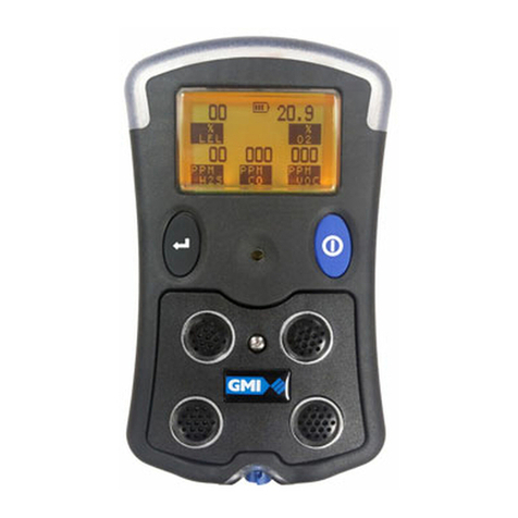
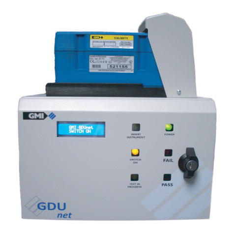
GMI GDUnet Instruction Manual

GMI
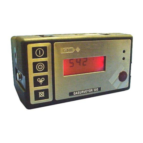
GMI Gasurveyor 500 Series Installation guide
Popular Measuring Instrument manuals by other brands

Fluke
Fluke a3001 FC Quick reference guide

Airport Lighting
Airport Lighting L-880 owner's manual

Eurotops
Eurotops 46041 manual

PCE Instruments
PCE Instruments PCE-TG 300-NO2-ICA user manual

Rice Lake
Rice Lake EVOLUTION Synergy 380 Technical manual

PRÜFTECHNIK
PRÜFTECHNIK VIB 6.195 Installation and operation instruction