GMI V!SA Instruction Manual

V!SA
(4-Gas Version)
UserHandbook

Issue 6
07/08/2013
Part Number: 66094
GMI welcomes comments on all our publications.
Your comments can be of great value in helping
us to improve our customer publications. Please
send any comments that you have to our Sales
Department at GMI. Contact details are provided
inside the back cover of this handbook.
Instrument Service / Repair contact details are also
provided inside the back cover of this handbook.
Copyright ©Gas Measurement Instruments Ltd 2005

i
COPYRIGHT
This User Handbook is copyright of Gas Measurement Instruments Ltd (GMI)
and the information contained within is for use only with the GMI V!SA.
Reproduction, in whole or in part, including utilisation in machines capable of
reproduction or retrieval without written permission of Gas Measurement
Instruments Ltd. is prohibited. Reverse engineering is not permitted.
LIABILITY
Every care has been taken in the preparation of this Handbook, but GMI Ltd.
do not accept any responsibility for errors or omissions and their consequences.
Information in this Handbook is subject to change without notice. This Handbook
does not constitute a specification or basis for a contract. Your statutory rights
under law are not affected.
MODIFICATION NOTICES
GMI aim to notify customers of relevant changes in the product operation and
maintain this Handbook up to date. In view of the policy of continuous product
improvement there may be operational differences between the latest product
and this Handbook.
This Handbook is an important part of the V!SA product. Please note the
following points:
• It should be kept with the instrument for the life of the product
• Amendments should be attached to this Handbook
• This Handbook should be passed on to any subsequent owner/user of
the instrument
• Although every care is taken in the preparation of this Handbook it does
not constitute a specification for the instrument.
SOFTWARE
Software supplied on EPROM or similar device for use in a particular product,
may only be used in that product and may not be copied without the written
permission of Gas Measurement Instruments Ltd. Reproduction or disassembly
of such embodied programmes or algorithms is prohibited. Ownership of such
software is not transferable and Gas Measurement Instruments Ltd. does not
warrant that the operation of the software will be error free or that the software
will meet the customer’s requirements.
DISPOSAL ADVICE
When no longer in use, dispose of the instrument carefully and with respect for
the environment. GMI will dispose of the instrument without charge if returned
to the factory.

ii
V!SA - USER HANDBOOK
SAFETY
• The instrument
trained personnel in a safe area.
• Batteries:
use.
See Section 4 : OPERATOR MAINTENANCE.
• Only GMI replacement parts should be used.
• and operational guidelines.
•
•
94/9/EC
AREAS OF USE
than 21% Oxygen.
• The instrument must be regularly serviced and calibrated by fully
trained personnel in a safe area.
• Batteries:Alkalinebatteries or *Rechargeablebattery pack must be
exchanged (*and recharged) in a safe area and fitted correctly before
use. Never use damaged batteries or expose to extreme heat.
See Section 4 : OPERATOR MAINTENANCE.
• Only GMI replacement parts should be used.
• If the instrument detects gas, follow your own organisation’s procedures
and operational guidelines.
• Gas can be dangerous and care should always be taken in its use.
• This equipment is designed and manufactured to protect against other
hazards as defined in paragraph 1.2.7 of Annex II of the ATEX Directive
94/9/EC
Any right of claim relating to product liability or consequential damage to any
third party against GMI is removed if the above warnings are not observed.
AREAS OF USE
Exposure to certain chemicals can result in a loss of sensitivity of the flammable
sensor. Where such environments are known or suspected it is recommended
that more frequent response checks are carried out. The chemical compounds
that can cause loss of sensitivity include Silicones, Lead, Halogens and Sulphur.
Do not use instrument in potentially hazardous atmospheres containing greater
than 21% Oxygen.
STORAGE, HANDLING AND TRANSIT
The batteries in the rechargeable pack contain considerable energy and care
shouldbe taken in theirhandling and disposal.
Theinstrumentis designed tohandleharsh environments. The instrumentis sealed
toIP65 and the sensingelements, sample inletand charging socket sealedto IP54.
Ifnotsubject to misuse or maliciousdamage,the instrument will providemanyyears
ofreliableservice.
Theinstrumentcan contain electrochemical sensors.Underconditions of prolonged
storagethesesensorsshouldbe removed. The sensor containspotentiallycorrosive
liquidandcareshouldbetakenwhen handling or disposing of thesensor,particularly
whenaleakissuspected.
Thereis no specialprecautions to be taken when the instrument isin transit.
WARRANTY
The GMI V!SA instrument has a warranty against faulty goods or workmanship
of 5 years. Consumable and Mechanical parts are not included in this. These
are covered under GMI standard warranty conditions. For details, please contact
GMI Ltd (UK).
iii
DECLARATION OF CONFORMITY
Refer to current
Declaration of Conformit
y
document Part No. 66250
(supplied with product)

iv
V!SA - USER HANDBOOK

v
REVISIONRECORD
Date Issue Description Of Change
06/06/2003 1
12/01/2004 2
12/06/2006 3
24/08/2010 4
06/06/2003 1 New User Handbook.
12/01/2004 2 Revised to include effect of
CN 2435, CN 2443, CN 2459,
CN 2493, CN 2494, CN 2496,
CN 2544 and CN 4014.
12/06/2006 3 Revised to include translations
update and effect of CN 4099,
CN 4137, CN 4146, CN 4178,
CN 4224 and CN 4226.
24/08/2010 4 Revised to include Declaration
of Conformity and effect of
CN 4271, CN 4302, CN 4479,
CN 4573, CN 4788, CN 4789,
CN 4836, CN 4851, CN 4857,
CN 4906 and CN 4957.
28/05/2012 5 Revised to include Marine
EquipmentDirective(MED) and
effect of CN 4926.

vi
V!SA - USER HANDBOOK
07/08/2013 6 Revised to include effect of
CN6280.

viii
V!SA - USER HANDBOOK
INTRODUCTION 1-1
1.1 GENERALDESCRIPTION 1-1
1.2 FEATURES 1-3
1.3 DATALOGGING 1-5
1.3.1 Viewing Data Logged Readings 1-5
1.4 HYDROPHOBICTYPE FILTER(S) 1-5
1.5 CONSTRUCTION 1-6
1.6 IDENTIFICATIONLABEL 1-6
1.7 PHYSICALPROPERTIES 1-6
1.7.1 Environment 1-6
1.7.2 Typical Flow Rate Information 1-6
1.7.3 Warm-up / StabilizationTime 1-6
1.7.4 Response Time (T90) 1-6
1.8 CERTIFICATION 1-7
1.8.1 Identification of Symbols 1-7
1.8.2 Performance 1-8
OPERATION 2-1
2.1 OPERATINGPROCEDURE 2-1
2.2 SWITCHINGTHEINSTRUMENTON 2-2
2.2.1 Instrument Identification 2-3

ix
CONTENTS
2.2.2 Battery Status 2-3
2.2.3 Time and Date 2-4
2.2.4 Calibration Due Date 2-4
2.2.5 Select Calibration Gas 2-6
2.2.6 Sensor Confirmation Check 2-7
2.2.7 Normal Operating Display 2-9
2.3 SWITCHINGTHE DISPLAYBACKLIGHT ON/ OFF
2-10
2.4 VIEWINGTHEMAXIMUMANDMINIMUM
RECORDEDVALUESSINCESWITCHON 2-10
2.5 ALARMSRESETORACKNOWLEDGE 2-13
2.5.1 Confidence Signal 2-15
2.6 SWITCHINGTHEINSTRUMENTOFF 2-15
2.7 REMOTESAMPLING(with pumpoption) 2-16
2.7.1 PumpOption: 2-16
2.7.2 Assisted Diffusion Option: 2-17
ALARMS 3-1
3.1 GASALARMS 3-1
3.1.1 FlammableLELAlarmLimit 3-1
3.1.2 Over-Range Flammable GasAlarm Function
3-1
3.1.3 Oxygen (O2) Alarm Limits 3-2

x
V!SA - USER HANDBOOK
3.1.4 ToxicAlarm Limits 3-2
3.2 ACKNOWLEDGEGASALARMS 3-5
3.3 HIGHFLAMMABLEGAS OVER-RANGEALARM
3-6
3.4 FAULTALARMS 3-8
3.4.1 Low Battery 3-8
3.4.2 Zero Fault 3-8
3.4.3 Zero Fault - Only applicable to instruments
with CO2 sensor fitted 3-10
3.4.4 Sensor Fault 3-12
3.4.5 Sample Fault (Pumped Instruments Only)
3-14
3.4.6 Low Flow - Only applicable to pumped
instruments supplied with this option. 3-14
3.4.7 Calibration Expired 3-15
3.4.8 Calibration Required 3-15
OPERATORMAINTENANCE 4-1
4.1 CLEANING 4-1
4.2 FILTERREPLACEMENT 4-1
4.2.1 Sensor Grille Filter 4-2
4.2.2 Sample Inlet Filter 4-4
4.2.3 In-line Hydrophobic Filter (Accessory)
4-6

xi
CONTENTS
4.3 BATTERY PACKS 4-8
4.3.1 Removing and Replacing a Battery Pack
4-10
4.3.2 Charging (Rechargeable) Battery Packs
4-12
4.3.3 ReplacingAlkaline Batteries 4-17
CALIBRATION 5-1
5.1 GENERALDESCRIPTION 5-1
5.2 CALIBRATION VALIDITY 5-2
ACCESSORIES 6-1
ADDITIONALINFORMATION 7-1
7.1 TRAINING 7-1
7.2 WORLDWIDE WEB 7-1
OPERATING INSTRUCTIONS A-1

xii
V!SA - USER HANDBOOK
INDEX i

1-1
INTRODUCTION
1.1 GENERAL DESCRIPTION
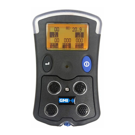
The GMI V!SA combines quality, ruggedness and
advanced technology in a user friendly, portable gas
detector. Small and lightweight, it is suitably certified to
recognised International Standards.
Fig. 1.1 V!SA Instrument
The V!SA is used for confined space monitoring, for
example, in sewers, underground piping or within tanks,
andotherpersonalmonitoringapplications.Itshighintensity
audible and bright visual alarms provide early warning of
dangerous gas levels.
1

1-2
V!SA - USER HANDBOOK
The instrument is operated via a single push button,
providing the user with a simple to use gas detector.
From one (1) up to four (4) gases can be monitored from
the following list:
Note: A five (5) gas version is also available. For details,
contact GMI Ltd.
• 0 to 100% LEL Hydrocarbons
• 0 to 25% Oxygen (O2)
• 0 to 100 ppm Hydrogen Sulphide (H2S)
• 0 to 1000 ppm Carbon Monoxide (CO)
• 0 to 30 ppm Sulphur Dioxide (SO2)
• 0 to 100 ppm Sulphur Dioxide (SO2)
• 0 to 10 ppm Chlorine (Cl2)
• 0 to 20 ppm Nitrogen Dioxide (NO2)
• 0 to 100 ppmAmmonia (NH3)
• 0 to 300 ppm Nitric Oxide (NO)
• 0 to 5% Carbon Dioxide (CO2)
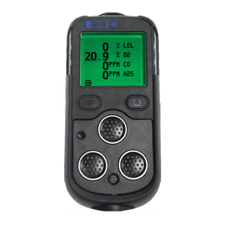
Theinstrumentdisplay identifiesthe gas(es)the instrument
is monitoring.An example of a four gas instrument display
is shown in Fig. 1.2:
Fig. 1.2 (4-Gas) Display Example

1-3
The display details the current gas readings and
operational / status information (as shown above) or the
instrumentcanbe setup todisplaya simple‘OK’ message.
Note: This Handbook describes the operation of a four
gas instrument configured in the most common format.
Onother models,operation issimilar tothe exampleshown.
Operational differences are highlighted if and where they
exist. Configurable options are available that allow the
instrumenttobe setup to suityour particularrequirements.
These options are detailed in italic text, where applicable,
andarealso detailedinthe‘CONFIGURATIONHANDBOOK’.
1.2 FEATURES
The main features of the V!SA instrument are:
• Integral impact resistant housing.
• Single button user operation.
• From one (1), up to four (4) gases detected
simultaneously. (A five gas version is also available).
• Alphanumeric display with screen light.
• High intensity audible and visual alarms.
• Confidence signal (green LED’s and/or sounder).
• Built-in electric pump (optional).
• Automatic data logging (optional).
• Three types of battery pack: Long Duration, Fast
Charge, and Alkaline. Each type of pack provides a
differentoperationallifetime. Thesetimes canbe found
in Table 1.1 and display battery life in hours, allowing
five (5) minutes of alarm per day.
INTRODUCTION

1-4
V!SA - USER HANDBOOK
• Instrument sealed to IP65 and sensing elements,
sample inlet and charging socket sealed to IP54,
making the instrument suitable for outdoor use
• A comprehensive range of accessories.
TNEMURTSNI
GNITAREPO
EDOM
EFIL/EPYTYRETTAB
/NOITARUDGNOL
EGRAHCTSAF ENILAKLA
LEL
61>61>
)DERARFNI(RI
61>61>
PMUP
61>61>
RI+LEL
2131
PMUP+LEL
2131
PMUP+RI
5161>
PMUP+RI+LEL
901
YLNOROSNESCIXOT
61>61>
Table 1.1 Battery Life

1-5
1.3 DATALOGGING
Optional data logging allows gas values, summary logs
and calibration details to be logged at regular intervals
and later downloaded to a Personal Computer (PC).
Datalogging is available as an option when ordering. It
cannot be retrofitted without returning the instrument to
GMI.
Note: If the Data logging option is selected, refer to
‘CONFIGURATION HANDBOOK’for furtherinformation on
data logging and overwriting set up options.
1.3.1 Viewing Data Logged Readings
Data logged readings can be downloaded from the
instrumentinto aPCusingGMI softwareand communication
adaptor. Contact our Sales Department at GMI for further
details.
1.4 HYDROPHOBIC TYPE FILTER(S)
A hydrophobic filter would normally be fitted to the
instrument but may be removed in certain applications,
forexample,when theinstrument isused todetectChlorine
or other reactive gases.
The filter(s), if fitted, should be checked regularly and
replaced if contaminated.
See ‘FILTER REPLACEMENT’ in Chapter 4, ‘OPERATOR
MAINTENANCE’, for further information.
INTRODUCTION

1-6
V!SA - USER HANDBOOK
1.5 CONSTRUCTION
The instrument is housed in a tough, impact resistant
moulded case. The instrument is sealed to IP65 and the
sensingelements,sample inletand chargingsocketsealed
to IP54. The instrument withstands physical impact testing
toEN 61779.
1.6 IDENTIFICATION LABEL
Each instrument has a unique serial number that appears
onthelabel alongwith the instrument’scertification details.
This serial number also appears on the instrument display
after switch on, during warm-up.
1.7 PHYSICAL PROPERTIES
Weight: 0.4 kg
Dimensions: 140 x 85 x 45 mm
1.7.1 Environment
Temperature Limits -20oC to + 50oC
Humidity: 0 to 95% R.H. non-condensing.
1.7.2 Typical Flow Rate Information
PumpedInstruments: Nominal pump flow rate is 0.5 to
0.7 litres per min. Max. 30 metres
(97ft.) sample line.
Typical flow fail rate is 0.1 to 0.2
litres per min.
1.7.3 Warm-up / Stabilization Time
< 40 seconds.
1.7.4 Response Time (T90)
Typical Oxygen (O2) response time: < 10 seconds.
This manual suits for next models
1
Table of contents
Languages:
Other GMI Measuring Instrument manuals

GMI
GMI GT series Instruction Manual

GMI
GMI PS500 Installation guide

GMI
GMI PS200 series Instruction Manual

GMI
GMI GT series Instruction Manual

GMI
GMI PS200 series User manual

GMI
GMI PS1 User guide

GMI
GMI GT series User manual

GMI
GMI PS1 Instruction Manual

GMI
GMI PS200 series User manual

GMI
GMI PS200 series User guide
Popular Measuring Instrument manuals by other brands

PCB Piezotronics
PCB Piezotronics 3713F12100G Installation and operating manual

Teledyne Lecroy
Teledyne Lecroy Frontline BPA 600 Hardware and Software User Manual

Crosby
Crosby COLT user manual

Growatt
Growatt Shine3G Quick Installation Guideline

GF
GF Signet 2552 user guide

Panasonic
Panasonic WJHD500 - DIGITAL DISC RECORDE Service manual