2. INSTALLATION
2.1. Preliminary Tests
It is always wise, before installation commences, to check the strain meters for proper function.
Each strain meter is supplied with a calibration sheet that shows the relationship between
readout digits and microstrain and also shows the initial no load zero reading. The strain meter
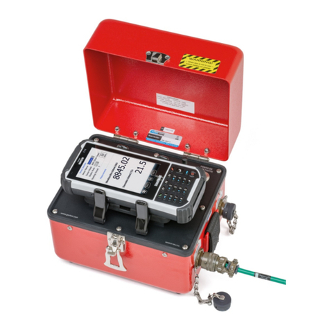
electrical leads (usually the red and black leads) are connected to a readout box (see section 3)
and the zero reading given on the sheet is now compared to a current zero reading. Under
normal circumstances the two readings should not differ by more than about 25 digits (10
microstrain). Shipping shocks may, however, cause larger shifts. If the reading is within 100
digits (40 microstrain) of the factory zero, and is stable, it is safe to proceed with the installation.
By pulling on the strain meter it should be possible to change the readout digits, causing them to
rise as tension increases.
Checks of electrical continuity can also be made using an ohmmeter. For the 4911A, resistance
between the gage leads should be approximately 50 Ω, ±10 Ω, for the 4911, 50 Ω, ±10 Ω.
Remember to add cable resistance when checking (22 AWG stranded copper leads are
approximately 14.7Ω/1000' or 48.5Ω/km, multiply by 2 for both directions). Between the green
and white should be approximately 3000 ohms at 25° (see Table B-1), and between any
conductor and the shield should exceed 2 megohm.
Note: Do not lift the strain meter by the cable.
2.2. Rebar Strain Meter Installation
2.2.1. Model 4911A
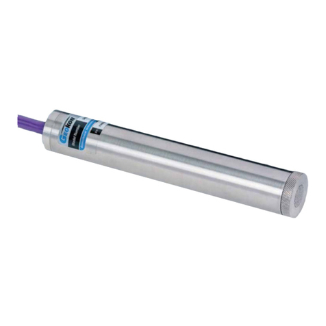
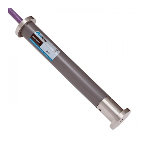
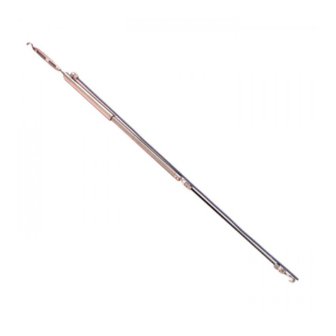
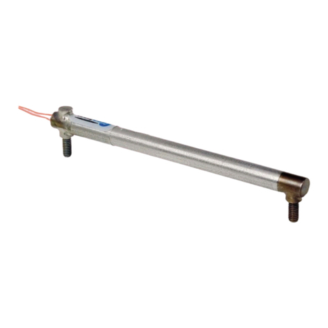
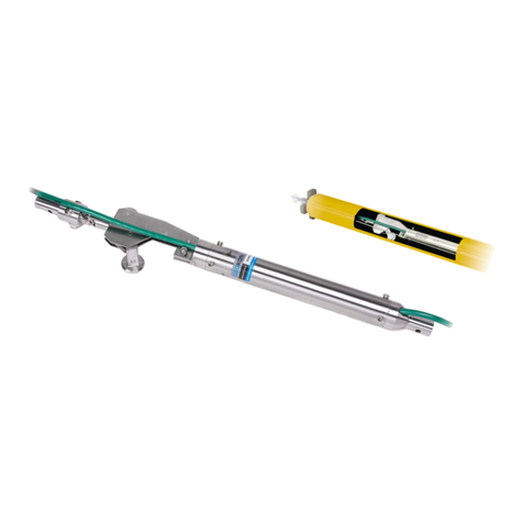
The normal procedure is to weld the strain meter in series with the reinforcing steel that is to be
instrumented on the site. For a typical installation see Figure 3. The strain meter is long
enough so that it may be welded in place without damaging the internal strain gage element
(Figure 1). However, care should still be taken to ensure that the central portion of the strain
meter does not become too hot as the plucking coil and protective epoxy could melt. In order to
prevent this it may be necessary to place wet rags between the weld area and the coil housing.
Also, take care not to damage or burn the instrument cable when welding. After welding, route
the instrument cable along the rebar system and tie it off every 3-4 feet (1 meter) using nylon
cable ties. Avoid using iron tie wire to secure the cable as the cable could be cut.
Be sure when installing the strain meters to note the location and serial numbers of all
instruments. This is necessary for applying the proper calibration factors and determining strain
characteristics when reducing data.
