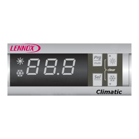
Lennox CLIMATIC II User manual

CLIMATIC
USER MANUAL
CHILLERS
V 2.2

User Manual - CLIMATIC II - Liquid chillers / Réf. RFL-
V2.2
-00 1
GENERAL CONTENTS
Page
CONTROL AND REGULATION........................................................2
OPTIONS ........................................................................................15
MACHINE FAULTS .........................................................................22
CIRCUIT FAULTS ...........................................................................29
COMPRESSOR FAULTS................................................................36
MISCELLANEOUS FAULTS............................................................42
KP02 DIGITAL CONSOLE...............................................................50
VISUAL DISPLAY UNIT (VDU) KP 07.............................................55
ELECTRONIC CARD DATA............................................................78

V2.2
-00 2
CONTROL AND REGULATION
SOMMAIRE
Page
IDLE FUNCTION..............................................................................3
CONTROL OF EVAPORATOR PUMPS..........................................4
COLD THERMOSTAT......................................................................5
HOT THERMOSTAT ........................................................................6
COLD REGULATION WITH GRADIENT ..........................................7
HOT REGULATION WITH GRADIENT.............................................8
CONTROL OF COMPRESSORS.....................................................9
CONTROL OF CAPACITY REDUCTIONS
FOR COLD REGULATION .............................................................10
CONTROL OF CAPACITY REDUCTIONS
FOR HOT REGULATION ...............................................................11
CONTROL OF ELECTRONIC EXPANSION VALVE .......................12
CONTROL OF CONDENSER FANS...............................................13
SPECIFIC VALVES FOR SCREW COMPRESSORS......................14

V2.2
-00 3
IDLE FUNCTION
Function
The idle function enables the machine to be stopped during certain times of the day or certain days of the week.
Outside the idle period, the refrigeration unit operates normally, in accordance with its instructions.
Description
Idle time is defined by 4 instructions (all included in the idle period) :
HDEBUTI óStart time of daily idle period
HFINI óEnd time of daily idle period
JDEBUTI óStart day of weekly idle period
JFINI óEnd day of weekly idle period
As an option, the customer has the facility of confirming or stopping the idle function by remote control, by
means of a hard contact connected to the logic input provided for this purpose (see wiring diagram). The
variable associated with this entry is MAARI.
If MAARI = 0, idle times are ignored.
If MAARI = 1, idle times are processed.
Example:
The user wishes to stop the machine:
- from Monday to Friday, from 7 p.m. to 6 a.m. the next morning
- all day on Saturday and Sunday.
In this case the instructions should be set as follows :
HDEBUTI= 19
HFINI = 6
JDEBUTI = 7
JFINI = 2
Note: By convention, Sunday is the first day of the week (Sunday = 1).

V2.2
-00 4
CONTROL OF EVAPORATOR PUMPS
Function
To control the flow of refrigerant in the evaporator
Description
There are two possible types of regulation, defined by the variable C2POMPE.
¶If C2POMPE = 0, the CLIMATIC controls one pump or none.
·If C2POMPE = 1, the CLIMATIC controls two pumps in normal / standby mode.
The user configures the C2POMPE parameter through switch 1 (or SW1) of CPU card.
FCase ¶:
The pump POMPE1 is in service if all the following conditions are satisfied:
ðAt least one on / off circuit n is ON (MAARn = 1). *
ðThe remote on / off switch for the machine is ON (MAARD = 1). *
ðThis is not an idle period (INOCCUP = 0). *
ðThe pump has been off for 1 minute or is already in operation.
ðThere is no electrical fault on the pump (DELECP1 = 1).
ðThere is no flow fault on the pump (DSDEB1 = 0).
* Cette condition n'est pas prise en compte si l'option "relance hors gel de la pompe" a été choisie et la
température d'air extérieur est inférieure à 2°C.
* This condition is not taken into account if the "anti-freeze pump start-up" option has been selected and the
outside air temperature is less than 2°C.
POMPE1 is always controlled by the CLIMATIC even if the installation pump is not electrically controlled by
the refrigeration unit.
If the customer controls the pump, he/she must comply with the following procedures:
•Pump start-up 1 minute before confirming the remote on / off switch for the unit.
•Pump off at least 2 minutes after MAARD is switched to 0.
FCas ·:
The pump POMPEk is in service if :
ðAt least one on / off circuit n is ON (MAARn = 1). *
ðThe remote on / off machine is ON (MAARD = 1). *
ðThis is not an idle period (INOCCUP = 0). *
ðPump POMPEk has priority (PRIP = k-1).
ðThe pump has been off for 1 minute or is already in operation.
ðThere is no electrical fault on the pump (DELECPk = 1).
ðThere is no flow fault on the pump (DSDEBk = 0).
* This condition is not taken into account if the "anti-freeze pump start-up" option has been selected and the
outside air temperature is less than 2°C.
The pump priority changes automatically once a week, on Monday at 6 p.m..
In the event of a fault occurring on the pump in service, the unit automatically transfers to the second pump,
on condition that the latter is available.
Note: The CLIMATIC waits 2 minutes before stopping the pumps after a request to stop the machine or
circuits, to avoid any risk of the evaporator freezing.


V2.2
-00 5
COLD THERMOSTAT
Function
To bring the temperature of the cooled fluid as close as possible to the set point by adapting the number of
compressors in service to the heat load in operation.
Description
The thermostat THER controls the switching on and off of compressors.
It is determined in accordance with the following parameters :
TEEG óChilled water input temperature (°C)
CONSREG óActive instruction for output of chilled water (°C)
This instruction is equal to CONSEA or CONSEB depending on the status of a logic
input associated with the variable CHPCONS.
Si CHPCONS = 0, CONSREG = CONSEA.
Si CHPCONS = 1, CONSREG = CONSEB.
(For regulation with air gradient, see page 7).
DELTAT óDesired temperature difference between water input and output (°C)
ENCL óOperating differential for a regulation stage (°C)
This variable is calculated as follows:
ENCL = ( DELTAT / No. Of compressors )
Example of a machine with 4 compressors:
With CONSREG = 7°C
et DELTAT = 5°C
⇒ENCL = 1,25°C
Remarque : The thermostat is only authorised to increase by a stage if the following conditions are satisfied :
ðTHER has not increased for at least 3 minutes.
ðThe chilled water output temperature is greater than the set point.
ðThe number of compressors in service is equal to the thermostat value.
THER
ENCL
1
2
3
4
0
CONSREG
TEEG
Compressor start-up Compressor stop
THER TEEG (°C) THER TEEG (°C)
0 ð1 8.25 4 ð3 10.75
1 ð2 9.5 3 ð2 9.5
2 ð3 10.75 2 ð1 8.25
3 ð4 12 1 ð0 7

V2.2
-00 6
HOT THERMOSTAT
Function
To bring the temperature of the heated fluid as close as possible to the set point by adapting the number of
compressors in service to the heat load in operation.
Description
The thermostat THER controls the switching on and off of compressors.
It is determined in accordance with the following parameters :
TEEC óHot water input temperature (°C)
CONSREG óActive instruction for output of hot water (°C)
This instruction is equal to CONSEA or CONSEB, depending on the status of a logic
input associated with the variable CHPCONS.
If CHPCONS = 0, CONSREG = CONSEA.
If CHPCONS = 1, CONSREG = CONSEB.
(For regulation with air gradient, see page 7).
DELTAT óDesired temperature difference between water input and output (°C)
ENCL óOperating differential for a regulation stage (°C)
This variable is calculated as follows:
ENCL = ( DELTAT / No. Of compressors )
Example of a machine with 4 compressors:
With CONSREG = 45°C
and DELTAT = 5°C
⇒ENCL = 1.25°C
Note : The thermostat is only authorised to increase by a stage if the following conditions are satisfied :
ðTHER has not increased for at least 3 minutes.
ðThe hot water output temperature is lower than the set point.
ðThe number of compressors in service is equal to the thermostat value.
THER
1
2
3
4
0
CONSREG
TEEC
ENCL
Compressor start-up Compressor stop
THER TEEC (°C) THER TEEC (°C)
0 ð1 43.75 4 ð3 41.25
1 ð2 42.5 3 ð2 42.5
2 ð3 41.25 2 ð1 43.75
3 ð4 40 1 ð0 45

V2.2
-00 7
COLD REGULATION WITH GRADIENT
Function
To adapt the regulation set point to the outside air temperature, for improved counterbalancing of solar heat
pick-up by the premises to be air conditioned.
Description
Le calcul du point de consigne de régulation CONSREG se fait en fonction des paramètres suivants :
TEA óOutside air temperature (°C)
CONSA ó1st reference air temperature selected (°C)
CONSAM ó2nd reference air temperature selected (°C)
TEGI óMinimum chilled water temperature instruction (°C)
CONSEG óRequired water instruction for air instruction CONSA (°C)
(CONSEG must be lower than +15°C).
CONSEI óRequired water instruction for air instruction CONSAM (°C)
(CONSEI must be greater than TEGI+2°C).
PENTEF óRegulation gradient (%)
The gradient is calculated using the following equation:
PENTEF = 100 x ( CONSEI - CONSEG ) / ( CONSAM - CONSA )
CONSREG = CONSEG + PENTEF x ( TEA - CONSA ) / 100
Example of regulation :
With CONSA = 20°C
CONSEG = 10°C
CONSAM = 35°C
CONSEI = 6°C
⇒PENTEF = -26.7 %
TEA
(°C) CONSREG
(°C)
20 10
25 8,66
30 7,33
35 6
CONSREG
CONSA
TEA
CONSEG
TEGI+2°C
PENTEF
CONSAM
CONSEI

V2.2
-00 8
HOT REGULATION WITH GRADIENT
Function
To adapt the regulation set point to the outside air temperature for improved counterbalancing of heat loss to the
outside from the premises to be heated.
Description
The regulation set point CONSREG is calculated according to the following parameters :
TEA óOutside air temperature (°C)
CONSAI ó1st reference air temperature selected (°C)
CONSA ó2nd reference air temperature selected (°C)
TECS óMaximum hot water temperature instruction (°C)
CONSEM óRequired water instruction for the air instruction CONSAI (°C)
(CONSEM must be less than TECS-2°C).
CONSEC óRequired water instruction for the air instruction CONSA (°C)
(CONSEI must be greater than 25°C).
PENTEC óRegulation gradient (%)
The gradient is calculated using the following equation:
PENTEC = 100 x ( ( CONSEC - CONSEM ) / ( CONSA - CONSAI ) )
CONSREG = CONSEC + ( PENTEC x ( TEA - CONSA ) / 100 )
Example of regulation :
Avec CONSAI = -10°C
CONSEM = 50°C
CONSA = 15°C
CONSEC = 30°C
⇒PENTEC = -80 %
TEA
(°C) CONSREG
(°C)
-10 50
-5 46
0 42
5 38
10 34
15 30
CONSREG
CONSAI
TEA
CONSEM
25°C
PENTEC
CONSA
CONSEC

V2.2
-00 9
CONTROL OF COMPRESSORS
Function
The compressors are started up and stopped in the order which avoids the anti-short cycle, as far as possible,
and evens out their operating times..
Description
FStart-up and stopping order for compressors
This order is determined by a “FIFO” (first in, first out) rule. This function incorporates the automatic,
instantaneous recording of a priority compressor which has become unavailable
FCompressor start-up and stopping
The compressor COMPmn starts up if all the following conditions are satisfied :
ðThe water circulation pump received the order to operate at least 1 minute earlier.
ðThe on / off switch for circuit n is ON (MAARn = 1).
ðThe machine is available (DISPOM = 1).
ðCircuit n is available (DISPOCn = 1).
ðCompressor mn is available (DISPOmn = 1).
ðThe regulation thermostat THER is greater than the number of compressors in service.
ðCOMPmn is the compressor defined by the FIFO rule as the next one to start up.
ðCOMPmn is not in anti-short cycle (ACCmn = 1).
The compressor COMPmn stops if at least one of the following conditions is satisfied :
ðThe remote on / off switch for the machine is OFF (MAARD = 0).
ðThe on / off switch for circuit n is OFF (MAARn = 0).
ðThe machine is unavailable (DISPOM = 0).
ðCircuit n is unavailable (DISPOCn = 0).
ðCompressor mn is unavailable (DISPOmn = 0).
ðThe regulation thermostat THER is less than the number of compressors in service and COMPmn is the
compressor defined by the FIFO rule as the next one to be stopped.
FExample of regulation with 4 compressors :
THER 0123434321232343210
Last one started up -1234-1---2 3 -4 1 - - - -
Last one stopped -----1-234- - 1- - 2 3 4 1
Compressor
number
In operation -11 2 1 2
31 2
3 4 2
3
42 3
4 1 3 4
14 1 11 2 1 2
32 3 2 3
42 3
4 1 3 4
14 1 1-

User Manual - CLIMATIC II - Liquid chillers / Réf. RFL-
V2.2
-00 11
CONTROL OF CAPACITY REDUCTIONS FOR HOT REGULATION
Function
To adjust the hot water output temperature as closely as possible to the set point by adapting compressor
capacity.
Description
Capacity reduction valves are only available on semi-hermetic reciprocating or screw compressors.
On a machine with several compressors, only the last one started up can modify its capacity. The other
compressors are maintained at full capacity.
The number of capacity reductions to be put into operation is defined by the thermostat THERR, in accordance
with the following 2 parameters:
TSEC óHot water output temperature (°C)
CONSREG óChilled water instruction (°C)
As soon as TSEC becomes greater than CONSREG+0.5°C, capacity is reduced. As long TSEC remains above
CONSREG + 0.5°C, an additional capacity reduction cuts in (if applicable) every 2 minutes.
If at least one capacity reduction is in service, one is stopped as soon as TSEC is less than CONSREG – 1°C.
As long as the TSEC condition is satisfied, an additional capacity reduction is stopped every 2 minutes.
Note :At start-up, the compressors are maintained at reduced capacity for 1 minute.
TSEC
THERR
0
temps
2 min
1 0 1
2
1 0
CONSREG
CONSREG+0,5°C
2 min

V2.2
-00 12
CONTROL OF ELECTRONIC EXPANSION VALVE
Function
To control correct filling of the evaporator with refrigerant in order to obtain highest efficiency, whilst protecting
the compressor against slugging.
Description
The expansion valve is controlled by Proportional + Integral + Derivative logic. The ideal theoretical opening
RDETAn of the expansion valve on circuit n is determined and compared with the actual opening. Depending on
the variation observed, an opening or closing order is issued to the expansion valve.
FCalculation of RDETAn
Theopening to be achieved RDETAn depends on the following parameters :
SURCHD óSuperheat instruction (°C)
TASPn-TBPn óSuperheat measured on circuit n (°C)
RDETn óOpening measured on expansion valve (°C)
I.e. ∆et the difference at time t between the measured superheat and the instruction:
∆et = (TASPn - TBPn) - SURCHD
REDTAn = RDETn + Kp .∆et + Ki .∑∆
t
ni-t
te+ Kd .∑∆∆
t
nd-t
1-tt )e-e(
FOrder issued to expansion valve
3 cas se présentent :
ðIf RDETAn > RDETn, the expansion valve must be heated (DETn=1) to open it to the desired opening.
ðIf RDETAn < RDETn, the expansion valve is not heated (DETn=0) so that it can close.
ðIf RDETAn = RDETn, the expansion valve is maintained at its current opening value by alternating start
and stop heating operations successively.
Note :Before starting up the first compressor on the circuit, the expansion valve is preheated to an opening
value calculated on the basis of the low pressure prevailing in the circuit. This procedure avoids any
risk of slugging at compressor start-up.
Derivative
Integral
action
Proportional action

V2.2
-00 13
CONTROL OF CONDENSER FANS
Function
To maintain as stable a condensation pressure as possible without fans cutting in too frequently.
Description
The CLIMATIC calculates the number of ventilation stages THVn required for the proper functioning of each
refrigeration circuit.
THVn depends on the following parameters :
PTHPn óCondensation pressure in circuit n (abs. bar)
TEA óOutside air temperature (°C)
HPHAUT óHigh pressure limit (abs. bar)
HPBAS óLow pressure limit (abs. bar)
The minimum difference between HPHAUT and HPBAS is 5 bar.
TEMPOV óTiming of raising or lowering of ventilation stage (s)
FFan operation
At the start-up of the first compressor on the circuit, as soon as high pressure becomes greater than
HPBAS+1bar, N fans are immediately started up (the number N depends on the outside air temperature).
When PTHPn exceeds HPHAUT, the thermostat is increased by one stage. If the pressure remains above
HPHAUT, THVn continues to be increased by one unit every T (time interval) :
.If HPHAUT < PTHPn HPHAUT+1bar, T = TEMPOV
. If HPHAUT+1bar < PTHPn HPHAUT+2bars, T = TEMPOV/2
.If PTHPn > HPHAUT+2bars, T = TEMPOV/4
FTurning off fans
Once PTHPn falls below HPBAS, THVn is reduced by one stage. As long as PTHPn remains below HPBAS,
THVn continues to be decreased by 1 every TEMPOV (time interval).
Note :When stopping a ventilation stage relates to a 2-speed fan, switching from fast to slow speed is
delayed by 5 seconds.
Setting
instructions
THVn
HPHAUT
HPHAUT+1bar
HPHAUT+2bar
HPBAS
HPBAS+1bar
time
PTHPn
.At t=0, start-up of
1st compressor
.N=1
.τ= TEMPOV
τ
τ
/2
τ
τ
/4
0
01234 5 4 3

V2.2
-00 14
SPECIFIC VALVES FOR SCREW COMPRESSORS
Liquid injection valve using intermediate suction
Function
To reduce the compressor discharge temperature thereby improving cooling on the compressor motor.
Description
The liquid injection valve INJLmn is open if:
. the compressor COMPmn is in operation
and . the discharge temperature TREFmn is greater than 100°C or the economy valve ECOmn is opened.
INJLmn is kept open as long as:
. the compressor COMPmn is in operation
and . the discharge temperature TREFmn is greater than 90°C or the economy valve ECOmn is opened.
Economy valve
Function
To increase refrigerating capacity by increased sub-cooling of the liquid refrigerant output from the condenser.
Description
The economy valve ECOmn is open if:
. compressor COMPmn is in operation and at full capacity for 2 minutes
and . the discharge temperature TREFmn is greater than
and . high pressure in circuit n PTHPn is greater than P1.
ECOmn is kept open as long as:
. compressor COMPmn is in operation and at full capacity
and . the discharge temperature TREFmn is greater than -2°C
and . high pressure in circuit n PTHPn is greater than P2.
θ(°C) P1 (absolute bar) P2 (absolute bar)
R22 65 11,9 11,2
R134a 40 7,7 6,7
R407C 45 13,5 11,7

V2.2
-00 15
OPTIONS
CONTENTS
Page
FREE-COOLING .............................................................................16
HEAT RECOVERY..........................................................................18
MANAGEMENT OF UNITS IN PARALLEL......................................19

V2.2
-00 16
FREE-COOLING
Function
To ensure refrigeration whilst optimising the use of free-cooling, thus limiting electrical consumption to a
minimum.
Description
FF Free-cooling outline diagram
TEEGFC óTemperature of chilled water input to free-cooling (°C)
TEEG óTemperature of chilled water input to the evaporator (°C)
TSEG óChilled water output temperature (°C)
TEA óOutside air temperature (°C)
V3VFC óThree-way free-cooling valve
FF Control of the three-way free-cooling valve:
V3VFC is fed if all the following conditions are satisfied :
ðTEEGFC is greater than the regulation instruction CONSREG.
ðTEA<TEEGFC-2°C.
ðThe chilled water circulation pump has been in operation for at least 30 seconds.
ðThe three way valve has remained off for 3 minutes.
ðThe free-cooling water input sensor is not defective.
V3VFC is kept connected as long as all following conditions are satisfied :
ðTEEGFC is not less than CONSREG.
ðTEA<TEEGFC.
ðThe pump is in operation.
ðThe free-cooling water input sensor is not defective.
FF Control of free-cooling fans
The number of ventilation stages required for the batteries is determined by the free-cooling thermostat
THERFC. This parameter depends on the temperature of the water input to the evaporator TEEG and on the
regulation instruction.
V3VFC
free-cooling fan
TEEG
TSEG
TEEGFC
free-cooling unit
evaporator
TEA

V2.2
-00 17
FREE-COOLING (CONT’D)
The thermostat is incremented by one stage if TEEG remains greater than CONSREG+0.5°C for over 3
minutes. As long as this condition on TEEG is satisfied, THERFC continues to be incremented by one stage
every 3 minutes.
If TEEG remains lower than (CONSREG-0.5°C) the free-cooling thermostat is reduced by one stage every 3
minutes.
When TEEGFC falls below the set point, all ventilation stages are halted.
If the compressor regulation thermostat THER requires at least one stage of regulation whilst free-cooling is in
service, the free-cooling thermostat is forced to its maximum.
The free-cooling fan n VENTFCn operates if:
. THERFC ≥n
and . V3VFC is in service.
FAuthorisation of compressor start-up
Authorisation of compressor start-up, in parallel with free-cooling operation, is defined by the variable AUTOCP
which is dependent on the following parameters :
V3VFC óThree-way free-cooling valve
THERFC óFree-cooling regulation thermostat
THER óCompressor regulation thermostat
AUTOCP is set to 1 if :
. THERFC is at its maximum and TEEG is greater than CONSREG for over 3 minutes
or . V3VFC is not fed.
AUTOCP is kept at 1 as long as :
. THER is strictly positive
or . V3VFC is not fed.
TEEGFC
TEEG
temps
CONSREG
CONSREG+0,5°C
CONSREG-0,5°C
TEEG / TEEGFC
3 min 3 min 3 min
THERFC
0012210

V2.2
-00 18
HEAT RECOVERY
Function
On air units with heat recovery condenser, to maintain the hot water output temperature as close as possible to
the instruction, whilst adapting the air condenser capacity to the excess thermal capacity to be discharged.
Description
FF Outline diagram of heat recovery process
FDetermination of heat recovery mode
Unit operation in heat recovery or total discharge mode is defined by the RECUP parameter which is set to 1 or
0 . RECUP is determined depending on :
FSR óRecovery condenser flow controller
TSECR óHot water output temperature (°C)
CONSEH óHot water instruction (°C)
RECUP is set to 1 if : .FSR is on for over 15 seconds
and .TSECR < CONSEH.
RECUP remains at 1 as long as : .FSR has not been off for over 15 seconds
and .TSECR < CONSEH+2°C.
FControl of air condenser fans
On switching to recovery mode, the ventilation thermostat for circuit n THVn is forced to 0 for 5 seconds.
If the high pressure of circuit n exceeds 23 bar, THVn is increased by 1 stage. The ventilation thermostat
continues to be incremented by 1 every TEMPOV (time interval) as long as the condition on the pressure is
satisfied. Every time THVn is incremented, the value of the hot water output temperature TSECR is memorised
in the variable MTSECR.
In recovery mode, if TSECR becomes lower than MTSECR whilst at least one fan is in operation, the ventilation
thermostat is decremented.
Note: On water units, the CLIMATIC does not include heat recovery
Heat recovery
water condenser
Air condenser

V2.2
-00 19
MANAGEMENT OF UNITS IN PARALLEL
Function
To provide staging of units in order to adjust the temperature of the cooled fluid as closely as possible to the set
point.
Description
¶Management of the installation by an independent CPU card (recommended configuration)
General regulation is by a KP01 independent of those which directly control the units. Dialogue between the
cards is by hard contact only, without chaining.
FOutline hydraulics diagram (case of chilled water production
FThermostat on units
The thermostat THERG controls switching on and off of the different installation units Gn.
THERG is calculated in accordance with the following parameters:
TBAL óWater temperature in the chamber (°C)
CONSEG óWater instruction for regulation of units (°C)
ENCLG óOperating differential for one unit (°C)
DIFETG óDifferential between units (°C)
Case of an installation with 4 machines :
ENCLG DIFETG
THERG
4
3
2
1
0
CONSEG
TBAL
TBAL
Solenoid
valve V2V1
Pump
Buffer
chamber
Evap. G1
unit
Evap. G2
unit
Evap. G3
unit
Evap. Gn
unit
Table of contents
Other Lennox Control Unit manuals

Lennox
Lennox Carel pGD1 User manual

Lennox
Lennox Harmony III User manual

Lennox
Lennox EIM Assembly instructions

Lennox
Lennox iHarmony 10C16 Assembly instructions

Lennox
Lennox 13J76 User manual

Lennox
Lennox CLIMATIC 40 User manual

Lennox
Lennox 84W88 User manual

Lennox
Lennox CLIMATIC 40 User manual

Lennox
Lennox V8MSBB01 User manual

Lennox
Lennox Zoning System LZP-4 User manual
Popular Control Unit manuals by other brands

Idesco
Idesco 9CD 3.0 user manual

Lenze
Lenze i500 Series Mounting instructions

Siemens
Siemens MOBY I ASM 421 Technical description

Sierra Wireless
Sierra Wireless AirPrime EM7690 Hardware integration guide

Marsupial
Marsupial Eurorack Assembly instructions

Global Fire Equipment
Global Fire Equipment ZMU Programming manual