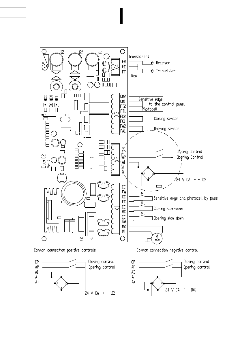
GMV OPER 02 User manual

Imp. n" Versione 0.1
01.06.2006
I : MANUALE DI INSTALLAZIONE ED USO
OPERATORE PORTE PERASCENSORI
EN : INSTRUCTION BOOK FOR USE AND INSTALLATION
DOOR OPERATOR FOR ELEVATORS
D :
INSTALLATIONS- UND BEDIENUNGSHANDBUCH
AUFZUGSTÜRANTRIEB
F : MODE D’INSTALLATION ET D’EMPLOI
OPERATEUR PORTES POURASCENSEURS

Indice
I
01 > cap. 1 Dispositivo oper 02
05 > cap. 2 Principio di funzionamento
06 > cap. 3 Regolazioni
07 > cap. 4 Funzionamento
08 > cap. 5 Caratteristiche elettriche
09 > cap. 6 Posizione della piastrina
per sostituzione cinghia Poly VJ
cap. 7 Manutenzione
Table of Contents
EN
10 > cap. 1 OPER 02 Device
14 > cap. 2 Operation principles
15 > cap. 3 Adjustments
16 > cap. 4 Operation
17 > cap. 5 Electrical features
18 > cap. 6 Location of the plate
for the replacement of belt Poly VJ
cap. 7 Maintenance
Inhaltsverzeichnis
D
19 > kap. 1 Antrieb Oper 02
23 > kap. 2 Funktionsprinzip
24 > kap. 3 Einstellungen
25 > kap. 4 Funktion
26 > kap. 5 Elektrische Merkmale
27 > kap. 6 Position der Platine zumAustausch
des Riemens Poly VJ
kap. 7 Wartung
Table des Matières
F
28 > chap. 1 Dispositif OPER 02
32 > chap. 2 Principes de fonctionnement
33 > chap. 3 Réglages
34 > chap. 4 Fonctionnement
35 > chap. 5 Caractéristiques électriques
36 > chap. 6 Position de la plaque pour le
remplacement de la courroie Poly VJ
chap. 7 Entretien

EN
1. DEVICE OPER 02
OPER 02 is designed to control automatic elevator doors driven by a dc motor.
The device carries out the following functions:
· Passive operation, one or two controls
All the adjustments are carried out by a trimmer
· 36 Vcc, 3A motor control with torque compensation and sensitive edge control.
Independent adjustment of the Operation Speed, Closing Speed and Sensitive Edge.
· PhotocellAmplifier
The circuit is designed for operation with a pair of transmitting-receiving (not reflection)
sensors.
· Voltage-free contacts towards the control panel
Contacts are provided for the open/close limit switches, photocells and sensitive edge.
The operator is controlled by controlling the current which circulates inside the motor
by means of an adjustment system without feed-back.
The continuous compensation of the torque enables to ensure stability throughout time
in the speed adjustments and – in particular – to supply the whole torque required at
the final stage of door closing.
The adjustment is not linked to the power supply voltage; subsequently, power supply
of the device can be at different voltages in standard operation and in emergency,
provided that the limits are complied with.
The information relevant to the position of the doors is detected by means of three
monostable magnetic contacts (NO), RA-RC-EC which detect respectively the beginning
of slowing-down at opening, the beginning of slowing down when closing and the end
of closing (See Figure 3).
FIGURE 1 –AT THE NEXTPAGE – SHOWSTHE LAYOUTOF THE CARDAND THE
CONNECTIONS TO THE EXTERNAL CIRCUITS.
10

CARD LAYOUT AND CONNECTION TO THE OUTSIDE CIRCUITS
11
FIG. 1
EN
WARNING: The door closing control from the panel is to be permanent, i.e. it must drop
only when the door opening one is given.

1.1 OPERATOR INSTALALTION
The operator is delivered with a preliminary wiring in order to facilitate the installation operations.
The operator package shall include the screws and brackets required for assembly. The supply
does not include – expect if expressly requested. The booth door sill, the booth parameter or the
programming keyboard.
1.Attach the brackets to the operator as shown in Figure 2.
2.Attach the operator – by means of the purposely-allocate brackets – onto the booth roof,
aligning it to the booth door sill. Tighten the attachment bolts thoroughly (See Figure 3).
12
FIG. 2
FIG. 3
52
60
160
min 30
H=2000
H=2185
35
750
5
40
H=0 41
SCREW M10 90
160
60
BOOTH DOOR SILL EDGE
SCREW M10 20
34
H=0
H=2000
H=2185
75
65
min 30
41
750 35
40
BOOTH DOOR SILL EDGE
EN

3.Attachment of the booth wings.After attaching the booth wings (See Figure 4), make sure that
the space between the wings and the booth shoulder between the door sill and the wing itself
(See Fig. 3). Should said space not be correct (5 mm), locate the wings into the exact position
by means of the purposely-allocated shims.
13
FIG. 4
EN

2. OPERATING PRINCIPLES
2.1 CONNECTIONS
I circuiti esterni sono collegati tramite connettori estraibili a morsetti.
La suddivisione dei circuiti nei vari connettori è stata realizzata in modo tale da semplificare le
operazioni di cablaggio.
- CONNECTOR X1
CODE DESCRIPTION
- CONNECTOR X2
CODE DESCRIPTION
- CONNETTORE X3
CODE DESCRIPTION
14
M1, M2
RA
CC
RC
CC
EC
CC
FA
CC
Motor connection
Opening slow-down monostable input
Input common
Closing slow-down monostable input
Input common
Monostable input – sensitive edge by-pass at closing end
Input common
Not used
Common input
A+
A-
AI
AP
CP
EF
Positive Power supply +
Negative power supply common
Positive or negative control (See scheme)
Door opening control input
Door closing control input (See scheme)
Not used
FA1
FA2
FC1
FC2
FT1
FT2
CM1
CM2
Opening sensor 1
Opening sensor 2
Closing sensor 1
Closing sensor 2
Photocell 1
Photocell 2
Moving edge 1
Moving edge 2
EN

FT
FC
FR
Photocell projector (red)
Photocell Sensor Common
Photocell receptor (transparent)
HXC
HCM
HFT
Sensor control ON = Contact closed
When the magnetic passes on sensors RAand RC, LED HXC issues
a pulse.
When the magnetic band is on sensor EC, LED HXC remains lit.
Intervention of the sensitive edge
Intervention of the photocell
3. ADJUSTMENTS
The adjustments are carried out independently by a trimmer.
The following table shows the list of the adjustments allowed.
CODE DESCRIPTION
3.1 ADJUSTMENT OF THE MAGNETIC SENSORS
1) Adjustthe closingand opening speeds through the trimmers, as specified inthe tablesabove.
2) Move sensors RA(opening slow-down) and RC (Closing slow-down) in order to obtain a
smooth closing-up of the door.
3) Adjust sensor EC:
A- Close the operator trolley until it leans onto the rubber washer (the operator cam is to
remain open);
B - Let reed EC move forward towards the magnet until LED HXC is lit on the card;
C - Tighten the screws of the reed support plate.
REMARK Sensor RA is to be involved by the magnetic band even when the door is fully open.
Sensor RC is to be involved by the magnetic band even when the door is fully closed.
Closing rate of trimmer P3
Opening rate of trimmer P2
Sensitive edge intervention torque. Trimmer P1
EN
- CONNECTOR X4
CODE DESCRIPTION
2.2 SIGNALING LED'S
CODE DESCRIPTION
15

EN
3. 2 CARD CONTROLS
Card OPER02 contains also two push-buttons for the operation in Test mode.
When power supply is connected to the card, if both the push-buttons are kept under pressure
for at least 1 second, the card moves into test mode, thus ignoring the control panel controls.
If the push-buttons are pressed again for 1 second, the card shall resume the standard operating
mode.
Anytime voltage issupplied to the card, itwill set into the standard operation mode, i.e.controlled
from the control panel.
4. OPERATION
The device does not carry out any control autonomously; it will carry out only the controls which
come from the control panel.
The sole exception is the stopping of the doors in case of intervention of either the moving edge
or the photocell.
4.1 DOOR OPENING
Door opening is carried out with the max torque available with no constraint.
The max. speed which can be reached depends upon:
· Trimmer adjustment <I>
· Resisting torque of doors and kinematics
The values ofAcceleration, Deceleration, Opening Slow Speed, Maintaining Current at the End
of Opening are fixed and unchangeable.
The doors open at the established speed until the monostable RAis reached.
Such monostable is to be located in such a way that the slow speed movement is reduced to
the minimum at the end of the deceleration.
If monostable RAis read before the end of the acceleration, as in the case of re-opening of the
doors, the beginning of the deceleration is delayed in compliance with the actual speed of the
doors.
If – in case of door closing - reopening is requested before the RAmonostable is exceeded - la
the reopening shall be carried out at slow speed.
The opening sensor contact (FA1-FA2) opens when the doors are completely open, when the
opening maintaining current is applied.
4.2 DOOR CLOSING
Door closing is carried out with torque control until monostable EC closes.
The doors operate at the established speed until they reach monostable RC. This monostable
is to be adjusted so that – at the end of the deceleration – the movement of the floor doors at
slow speed is reduced to the minimum.
If monostable RC is read before the end of the acceleration, the beginning of the deceleration
is delayed based upon the actual speed of the doors.
16

17
The values of Acceleration, Deceleration, Closing Slow Speed, maintaining Current at End of
Closing are fixed and unchangeable.
The Closing Sensor contact (FC1-FC2) opens when the doors are completely closed, when
monostable EC is read.
The Max torque level is adjusted by Trimmer II
If – during the closing operation – The max torque is exceeded when monostable EC is
open, the motor stops immediately, LED HCM lights up, and the signal is sent to the control
panel by contact CM1 CM2. The door remains in the position in which it is until the closing
control is removed and the command is given again.
4.3 PHOTOCELL AMPLIFIER
OPER02 is provided with an amplifier for the pair of photocells of the active transmitter-receiver
(not reflection) type, model OPTEA IRS 103 or equivalent.
The interruption of the photocell immediately stops the motor, LED HFT lights up and the
information is sent to the control panel through contact FT1 FT2.
The door thus remains in the position in which it is until the closing control is removed and a new
command is given.
When the doors are completely closed, the photocells are by-passed.
If the system is not provided with photocells, do not connect output FT1 FT2
5. ELECTRICAL FEATURES
Supply Voltage on terminals
s A+, A-
Power Supply protection:
Motor Protection:
Voltage on inputs AP and CP:
Pour of the outputs contacts:
Minimum current on the contacts
Ambient Temperature
24...48 Vdc obtained by an alternate current of 18...30V
ac, 150W
External by fuse 4A
Internalwith 23.15Afuses. The power section is protected
for both temperature and current
12…48 Vcc.
1A/48Vcc, 1A/125Vca.
10mA 12V
5°C…40°C
EN

18
6.
PLATE POSITION TO REPLACE BELT POLY VJ
7. MAINTENANCE
At each maintenance intervention, check the following points:
· Wear of the shoes
· Cleanness of guideways and door sills
· Inspect for any damage to the wings
· Electric contacts
· Cleanness of the mating and sliding wheels and relevant guideways
WARNING
· Do not lubricate the guideways
· Do not lubricate the transmission belts
· Do not lubricate the wheel bearings
IF THE DEVICE DOES NOT WORK:
1) MAKE SURE THAT THE VOLTAGE ON TERMINALS A+ A- IS WITHIN 24 AND 48VDC
2) MAKE SURE THAT FUSES F1 AND F2 ON THE CARD ARE NOT INTERRUPTED
3) MAKE SURE THAT THE MAGNETIC SENSORS ARE OPERATIONAL (THIS CAN BE EASILY
CHECKED BY MEANS OF AN OHMMETER OR CIRCUIT TESTER. MAKE SURE NOT TO SUPPLY
THE CARD SENSOR INPUTS.
4) IF LED HFT REMAINS LIT, CHECK THE CONNECTIONS OF THE PHOTOCELL SENSORS.
5) IF LED HCM LIGHTS UP WHEN THE DOORS CLOSE :
A - CHECK THE GOOD MECHANICAL SLIDING OF THE DOORS;
B - ADJUST TRIMMER II.
6) IF THE MOTOR HAS NO THRUST TO CLOSE THE DOORS:
A - ET THE CARD INTO MANUAL MODE (PRESSING BOTH THE RED PUSH-BUTTONS FOR
APPROX. 1 SECOND);
B - CLOSE THE BOOTH DOORS BY THE CLOSING PUSH-BUTTON, MANUALLY HELP THEM IF
THE CLOSE WITH DIFFICULTY. IMPORTANT: THE OPERATOR STRUCTURE IS TO CLOSE
AS WELL;
C - GIVE A SHORT PULSE WITH THE RED PUSH BUTTON IN OPENING AND THEN IN CLOSING
FOR 1 SEC APPRO;
D - WAIT FOR APPROX. 2 MINUTES WITHOUT GIVING ANY COMMAND.
THIS PROCEDURE ENABLES THE CARD TO ACQUIRE THE MOTOR DATA
FIG. 5
EN
15mm
Once the position of the plate is ascertained,
loosen the pulley on the opposite side of the
plate to loosen the toothed belt. Once the belt
is loose, extract belt Poly Vj by letting it slide in
your hands.
To reinstall the plate with the Reed in the right
position, and to give the right tightening to belt
Poly VJ, the following operations should be
carried out.
Locate the plate as indicates in Figure 5 and
tightenit thoroughly,belt PolyVj byletting itslide
on the pulleys. To complete, locate the toothed
belt back to the original position.

ITALY
GMV S.p.A.
Via Don Gnocchi, 10
20016 Pero (MI)
Tel. +39 02 339301
Fax +39 02 3390379
e-mail: info@gmv.it
www.gmv.it
REALIZZAZIONE GRAFICA TORINO - ITALY - www.offdesign.it
Table of contents