Henderson Evolve Glass SIM Kit User manual

Evolve –Glass SIM Kit
DOCUMENT TYPE = FITTING INSTRUCTIONS ORIGINAL LANGUAGE = ENGLISH
Maximum door weight = 40kg per leaf –total system 80kg
Maximum door width 2 x 2mtr Track = 760 - 1058mm (Up to 2035 mm clear opening)
About this document
This document addresses qualified personnel only. The mounting must be done by technically educated,
trained and qualified personnel. Electrical wirings have to be completed by suitably qualified specialists.
These instructions describe how to install the track & sliding door gear –for operation of the drive motor & Wiring detail
for the addition of switches & or sensors please refer the Evolve Motor and Wiring Fitting Instructions supplied
The manufacturer’s specifications must be respected, in especially maximum weight restriction of the door leaf. Any
other use of this product is considered inappropriate use.
It is not guaranteed that this product will work in combination with fittings, motors or other electronic devices
supplied by other manufactures.
The appliance is only to be used with the power supply unit provided.
Before you commence work, please read through these instructions. Please store these instructions in a safe place
and pass them on to any future owners. Damage resulting from non –compliance with these instructions and safety
instructions will void the warranty. PC Henderson nor the motor unit manufacturer will assume liability for any
consequential damage.
Fixings required (Not supplied by PCH)
We recommend that suitable wall fixings and screws with a Safe Working Load of at least 80kg are used.
Contents of Kit
80kg

Installations –End elevations
Tools required
Electricians
Screwdriver
Posi Head
Screwdriver
3, 4 & 5mm Allen
keys
Scissors
Torque Wrench
and 6mm bit
Electric Drill &
twist drill
Tape Measure
Spirit Level
3, 10 & 13mm
Spanner

Installation - System layout
CLOSED POSITION

Quick overview –Wiring wall mounted socket
For detailed operation and programming instructions please consult the separate Evolve Motor and Wiring Fitting Instructions supplied
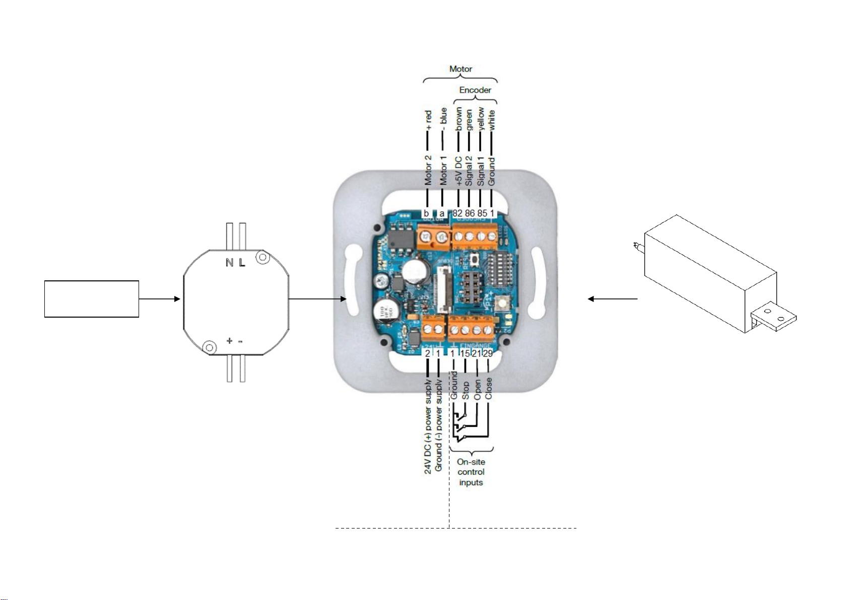
Fused Spur
(Not PCH)
Motor Unit
24V Transformer
Wall mounted control device inputs
Transformer input
Remote sensor or
additional switch input
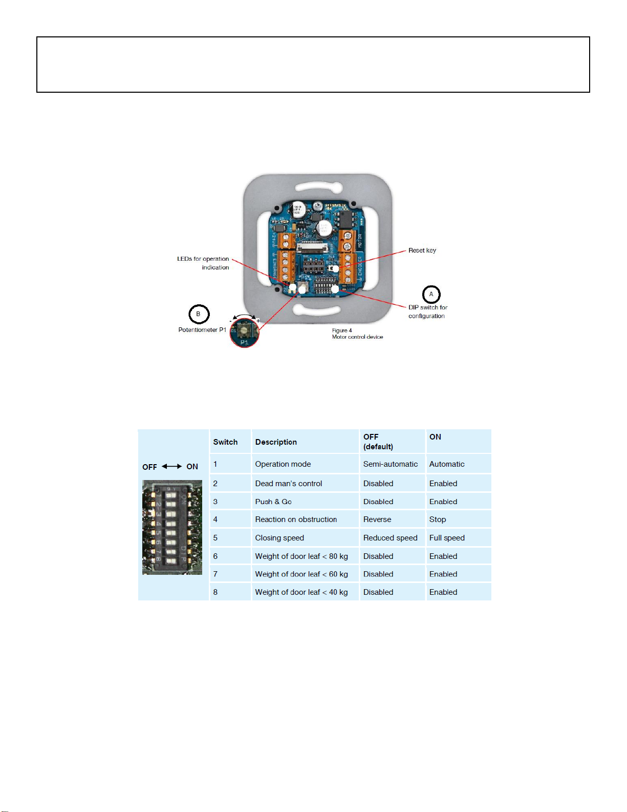
Initial Configuration
The configuration is set via the potentiometer P1, the DIP switch and the reset button. The function of these
elements is described in the following section.
Changes to configuration will only take effect once the configuration mode has been selected, modified and
then exited.
A –Configuration of DIP switches - Set desired parameters, while power is off.
B –Potentiometer Detail –Automatic closing delay time
To prolong automatic closing delay time –Turn potentiometer Clockwise
To reduce the automatic closing delay time –Turn potentiometer Anti clockwise
NOTICE: Potentiometer have a right and left stop point –which must not be overtightened. Adjust
potentiometer slightly with an appropriate tool. Damage to control device may result in malfunction.
Quick overview –Wiring wall mounted socket
For detailed operation and programming instructions please consult the Evolve Motor and Wiring Fitting Instructions
supplied

1. Operation mode semi- automatic / automatic
When semi-automatic mode is set the drive will not close automatically. The potentiometer is without function.
When the automatic mode is set the drive closes automatically.
2. Dead man’s control:
When dead man’s control is activated the drive will only operate, as long as an input is applied.
Switch 1 is inactive, when dead man’s control is selected.
3. Push & go:
With push & go enabled the drive starts to move, as soon as the door leaf is pushed manually.
4. Reaction on obstruction:
When reverse is set the drive stops and starts to move in the opposite direction, as soon as an obstruction is detected.
Otherwise it will stop until a new command is given. This is only possible in semi-automatic mode).
5. Closing speed:
By default the closing speed is slower than the opening speed. The closing speed can be set as fast as the opening speed, by
setting this switch to ON>
6. To 8. Maximum door speed
The maximum speed has to be set via these switches.
Maximum speed is dependent on the door leaf weight according to DIN EN 18650.
6: Weight of door leaf up to 80 kg > Maximum speed is 20cm/s
7: Weight of door leaf up to 80 kg > Maximum speed is 23cm/s
8: Weight of door leaf up to 80 kg > Maximum speed is 26cm/s
When no switch is activated, the lowest speed is set (20 cm/s).
When more than one switches are activated, a reduced speed is set (12 cm/s).
Perform Reset
Switch power supply on.
Control device in delivery status or after power cut:
Red LED blinks continuously twice with a short break of 1.5sec.
Press RESET for about 2 seconds.
Red LED blinks continuously.
Check driving direction of motor with control keys:
When pressing OPEN, door has to open and when pressing CLOSE, door has to close.
→ when driving direction is wrong:
Swap motor cables (terminals MA and MB), check driving direction again.
Move door in middle position by pressing and holding the control keys.
Press RESET for about 2 seconds.
Red LED lights up permanently,
green LED lights up during motor activity.
Door moves in the open position,
Door moves in the closed position,
Door moves in the open position.
LED’s go out.
Check functionality
Test, if the door shows desired behavior.
In case of malfunction check electrical connections and configurations.
→for electrical connections refer to chapter 5.3 of the Evolve Motor and Wiring Fitting Instructions supplied
→for configuration refer to chapter 6.1 of the Evolve Motor and Wiring Fitting Instructions supplied
→Repeat initial operation, if necessary.
Initial operation is completed, when function is correct.
Quick overview –Wiring wall mounted socket
For detailed operation and programming instructions please consult the separate Evolve Motor and Wiring Fitting Instructions
supplied
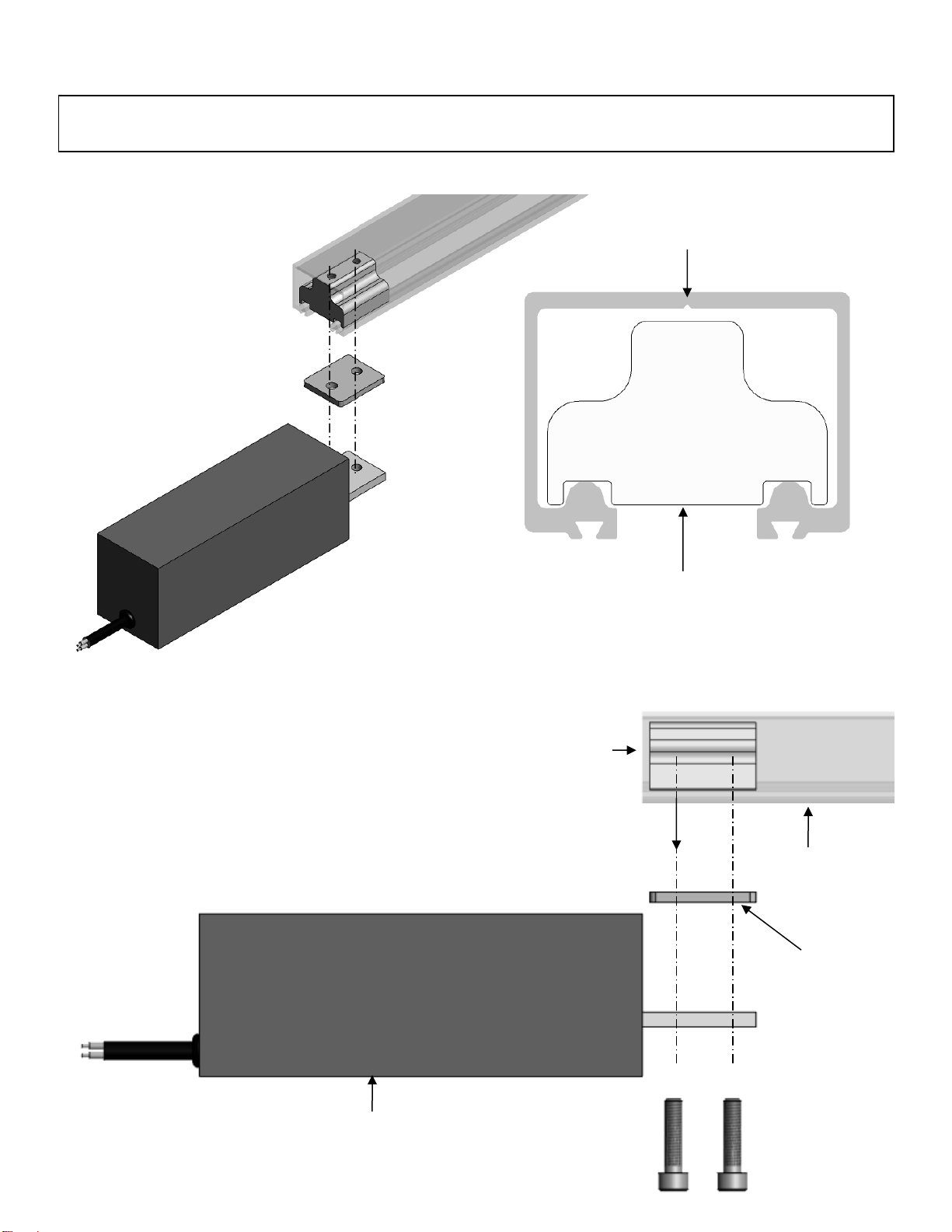
1. Secure motor unit to track by inserting block into track and tightening bolts to clamp over
bottom of track
Track
Connector block
Connector Block
Spacer
Track
Motor

M6x25 Bolts
180mm Offset to
accommodate door under
motor unit
2. Door and hardware preparation (overview)
3. Attach glass clamps (Panel positioned under motor highlighted)
4. Attach belt clamp location clamp centrally (ensure correct belt clamp orientation see panel 2)
a. Position first half of glass clamp
b. Locate second half of glass clamp over knee of first
c. Secure glass clamp with screws
d. Attach spacer block with screws to top of clamp
e. Attach belt clamp with screws on to top of spacer
a. Position first half of glass clamp
b. Locate second half of glass clamp over knee of first
c. Secure glass clamp with screws
a.
b.
c.

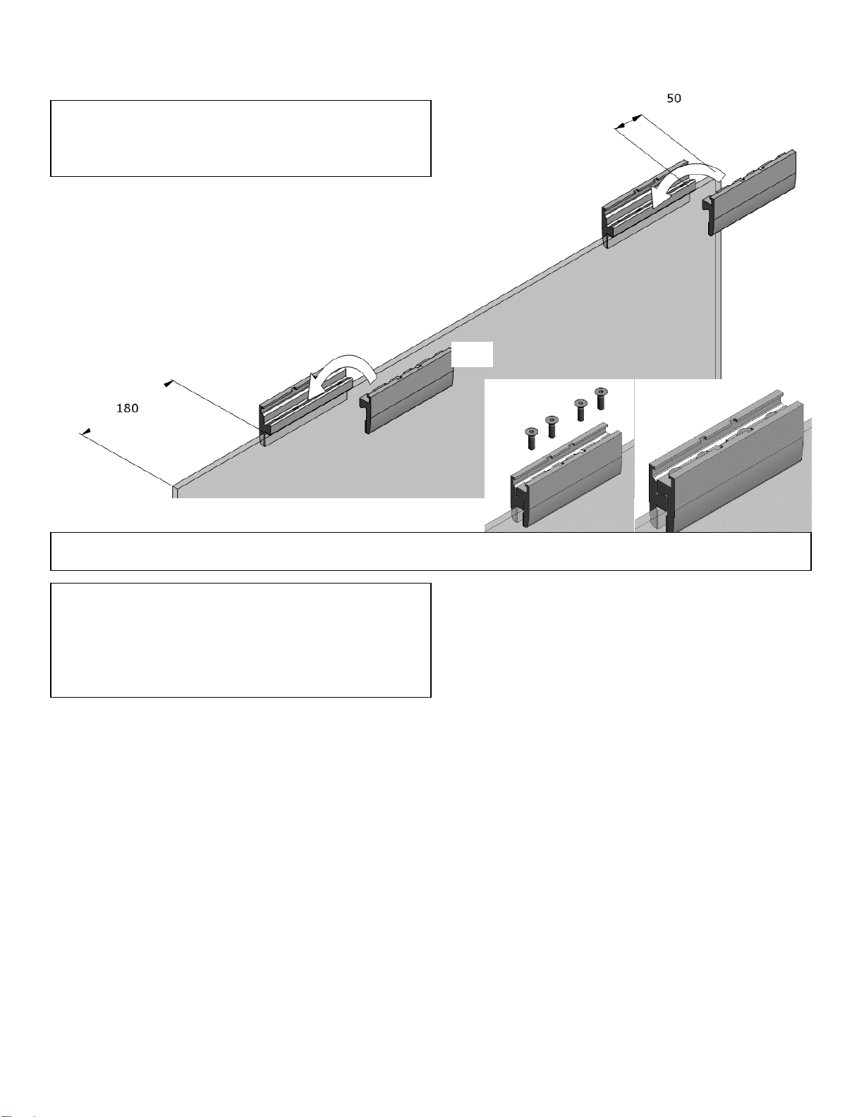
7. Insert track components
5. Secure track in face fixing installation –
spacing between brackets is 600mm MAX
(Use suitable wall anchors –NOT PCH)
6. Secure track soffit fix installation –spacing
between brackets is 600mm MAX
(Use suitable wall anchors –NOT PCH)
1/SS bracket
Fit suitable wall anchors
a.
d.
c.
b.
e.
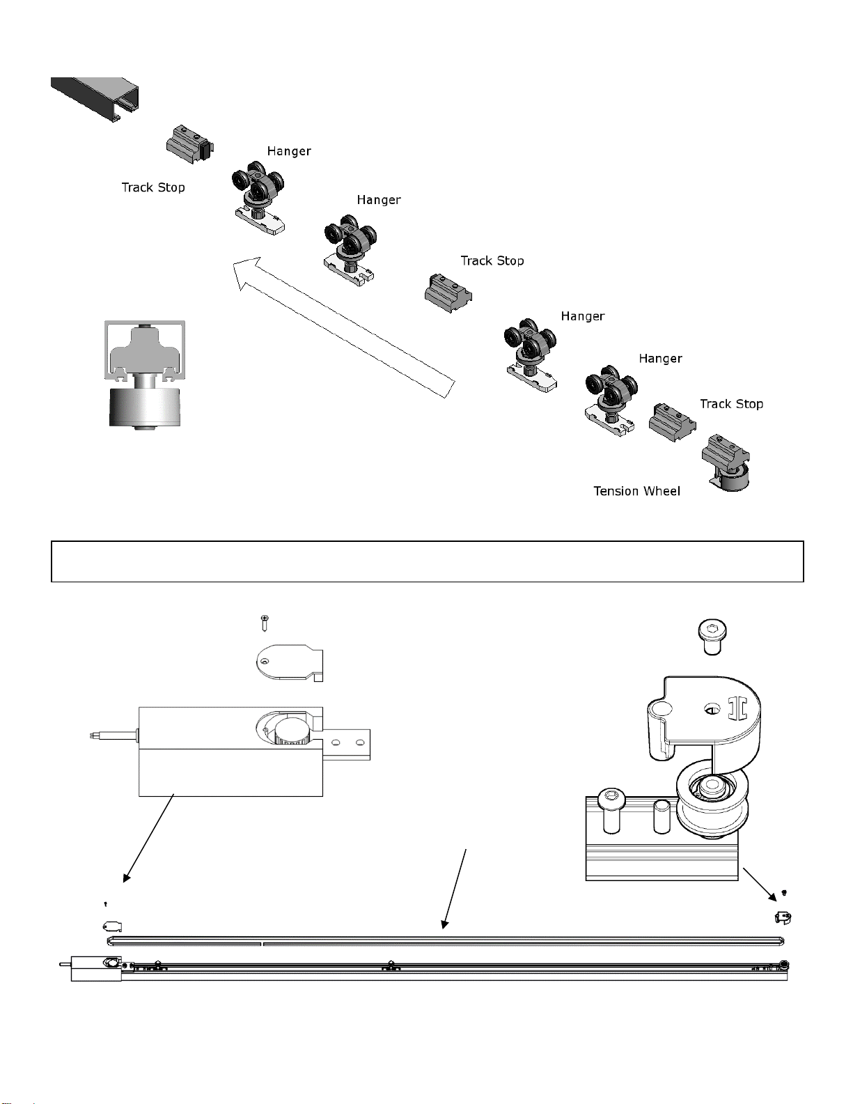
Toothed belt
Tension wheel
arrangement in track
8. Remove covers to allow toothed belt to be attached
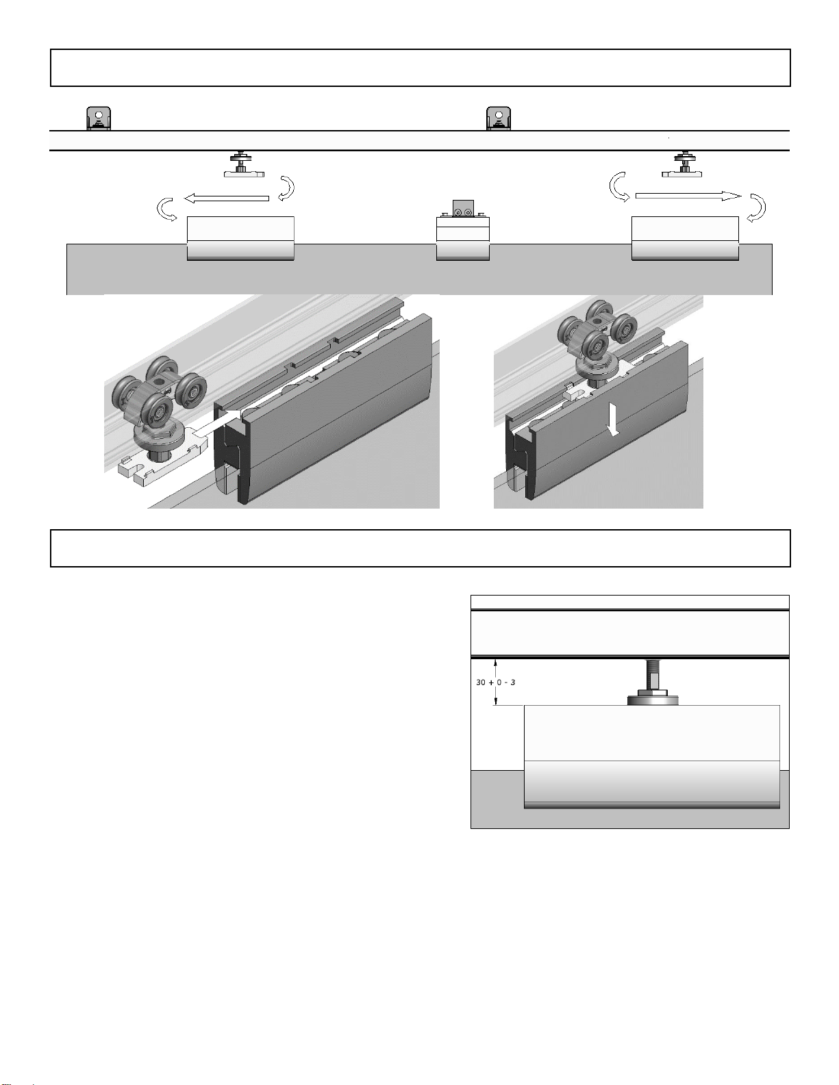
9. Hang glass door
10. Set door height
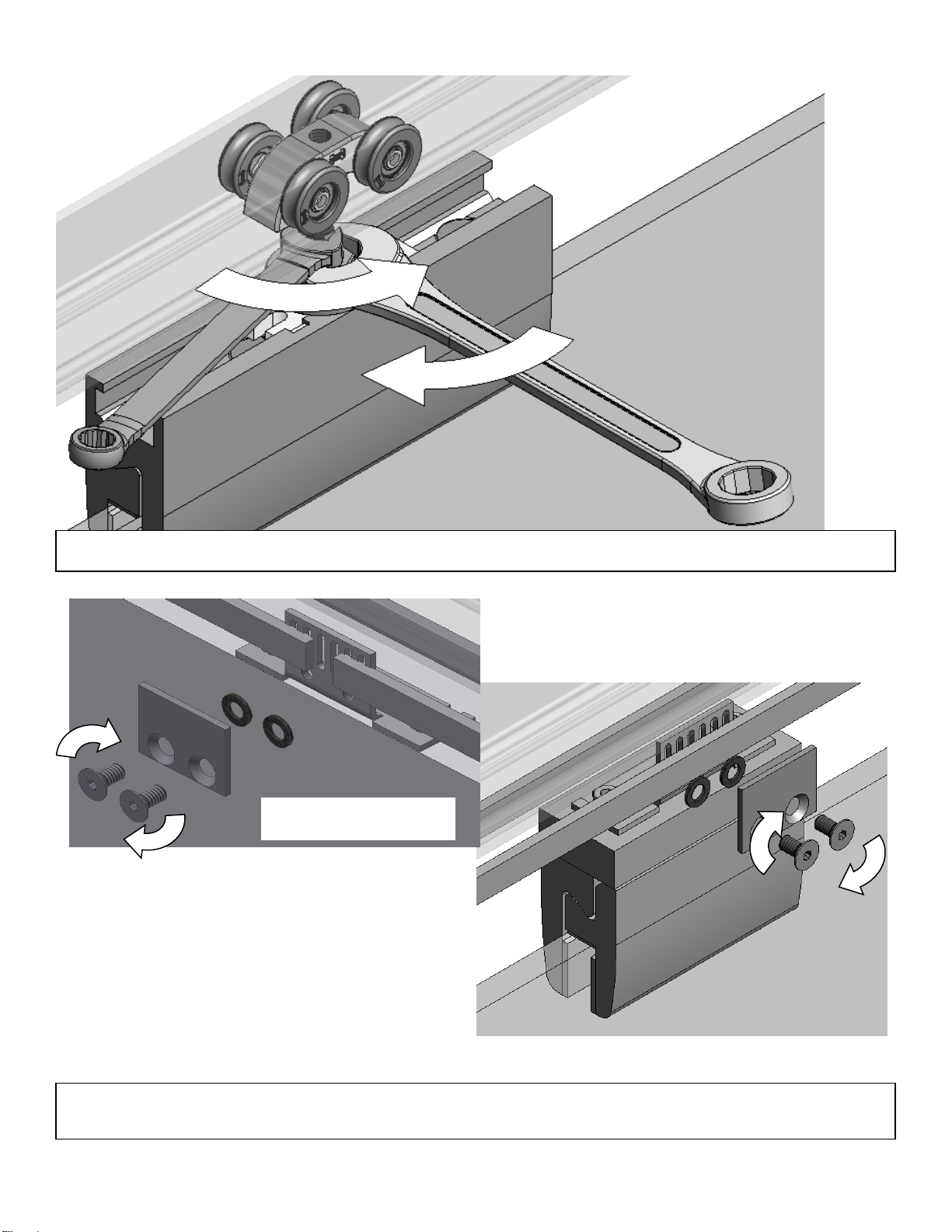
12. Tension toothed belt –Push tension wheel assembly so that the belt is torte and secure
assembly in position by tightening the M6 grub screw
11. Loosen belt clamp –Cut belt to length –Tighten to secure belt
Tighten to clamp belt

14. Set track stops to limit travel
Tighten
once
position
set
13. Fit Door Guide using spirit level
Adjust door stop if required before
fixing to ensure door is vertical

Please Note
The original language of these instructions are English.
The airborne noise of the system under normal operating conditions
does not exceed 70dB (A).
General Safety Precautions
This installation is intended for professionally competent personnel
only.
Installation, Electrical connections and adjustments must be performed
in accordance with Good Working Methods and in compliance with
applicable regulations. Before installing the product, carefully read the
instructions. Bad Installation could be hazardous.
The packaging material (plastic, polystyrene, etc.) should not be
discarded in the environment or left within the reach of children, as
these are a potential source of hazard.
Before installing the product, make sure it is in perfect condition.
Do not install the product, make sure it is in perfect condition. Do not
install the product in an explosive environment and atmosphere; gas or
inflammable fumes are a serious risk hazard. Before installing the
system, ensure all structural changes relating to safety clearances and
protection or segregation of all areas where there is a risk of being
crushed, cut or dragged, and danger areas in general.
Make sure the existing structure is up to standard in terms of strength
and stability.
Each installation must clearly show the identification details of the
motorized door or gate.
Apply hazard area notices required by applicable regulations.
The electricity supply must be isolated at tis source before attempting
installation or maintenance.
Disclaimer
PC Henderson nor the motor unit manufacturer take responsibility for
failure to use Good Working Methods in building the frames to be
motorized or for any deformation occurring during use. PC Henderson
and the motor declines all responsibility in the event of component
parts being fitted that are not compatible with the safe and correct
operation.
For repairs or replacements of products only original spare parts must
be used.
Installer responsibility
The installer should provide technical documentation once the
installation is complete, this should include.
- EC declaration of conformity with machinery directive
- Installation manual
- Maintenance / Trouble shooting guide (supplied in the drive
unit manufacturer operation manual)
- The installer is responsible for affixing final CE mark upon
the installation.
668775 –LVL02 –JUNE 2019
Tighten to position stops

Manufacturers Declaration of Incorporation
Manufacturer: PC Henderson Ltd
Durham road
Bowburn
Durham
DH6 5EN
Telephone: 0191 3777345
Fax: 0191 3773166
Hereby declares that the electromechanical automatic door operating
system. Evolve
Evolve Glass
Evolve SIM
Are intended to be incorporated into machinery or to be assembled
with other machinery to constitute machinery covered by directive
2006/42/EC
It is in conformity with the provisions of the following directives.
Electromagnetic Directive 2004/108/EC
Low Voltage Directive 2006/95/EC
The technical file is maintained at:
PC Henderson Ltd
Durham road
Bowburn
Durham
DH6 5EN
The authorized representative located within the community is
Fergus Pickard
Product Development Director
PC Henderson Ltd
Durham Road
Bowburn
Durham
DH6 5EN
The above named undertakes to transmit in response to a reasoned
request by national authorities, relevant information on the partly
completed machinery.
Fergus Pickard, Product Development Director
Bowburn, Durham
19/10/17
Avoid operating in the proximity of moving mechanical parts
Do not entre the field of danger of the motorised door while in
motion.
Do not obstruct the motion of the motorised door as this may
cause a situation of danger.
Do not lean against of hang on the barrier when it is moving.
Do not allow children to play or stay within the field of action of
the motorised door.
Keep remote control or any other control devices out of reach
of children, In order to avoid possible involuntary activation of
the motorised door.
In the case of breakdown or malfunction of the product,
disconnect form the mains, do not attempt to repair or
intervene directly & contact only qualified personnel.
Failure to comply with the above may create a situation of
danger.
All cleaning maintenance or repair work must be carried out by
qualified personnel.
In order to guarantee that the system works efficiently and
correctly it is indispensable to comply with the manufacturers
indications thus having a periodic maintenance of motorised
door carrier out by qualified personnel. In particular regular
checks are recommended on order to verify that the safety
devices are operating correctly.
All installation, maintained and repair work must be
documented and made available to the end user
Operating Instructions for Evolve Automation Sliding Door System
Release Operation
In the event of malfunction or these is no mains power, move the door manually.
General Safety Precautions
The following precautions are an integral & essential part of the product and must be supplied to the end user. Read them carefully
as they contain important indications for the safe installation, use and maintenance. These instructions must be kept and forwarded
to all possible future users of the system. This product must be used only for that which it has been expressly designed; any other
use is to be considered improper and therefore dangerous.
The manufacturer cannot be held responsible for possible damage caused by improper erroneous or unreasonable use.
Installer
Installer training available upon request, please note this attracts a fee.


EC Declaration of Conformity –Machinery Directive 200642/CE Schedule II Part 2
Manufacturer:
PC Henderson Ltd
Address:
Durham Road, Bowburn, Durham, DH6 5EN
Name and address of authorized Installer:
Hereby Declare:
Installation at: (Installation address)
Conforms to Directive:
States that it fulfils the application portion of the following standard
Date & Location of signature:
Signature of the person legally responsibility:
This completed document forms part of the European conformity (CE marking) - to be completed by installer and
forwarded to end user.
Evolve –80kg
Evolve –SIM Kit
Evolve - Glass
2006/42/CE –Machinery directive

Must be kept for ten years from installation date.
This manual suits for next models
1
Table of contents
Other Henderson Door Opening System manuals

Henderson
Henderson HUSKY 100 User manual

Henderson
Henderson SIM100 User manual

Henderson
Henderson Easyclose User manual

Henderson
Henderson SIROCCO User manual

Henderson
Henderson EVOLVE POCKET DOOR PRO Series User manual

Henderson
Henderson HUSKY Folding 25 Series User manual

Henderson
Henderson HUSKY 50 User manual

Henderson
Henderson Bifold User manual

Henderson
Henderson MARATHON FDK1 User manual

Henderson
Henderson SIM100 User manual


