55
Dental use equipment, for actuation and control of the syringe, rotary instruments and
others, providing the best proximity to the operative eld; ambidextrous (serves right and
left-handed users).
Set made of steel structure with ABS body injected with anti-UV protection. Flat paint
high gloss epoxy-based, cured in an oven at 250 ° C, with phosphate treatment corrosion
resistant and cleaning materials.
FLEX type pneumatic Model with stroke limiter stop. Attached to the chair, with wide
horizontal and vertical movement, with pneumatic locking, powered by button located
under the handle of the equipment, providing smoothness in movements and stop at the
desired position.
Movement of tips through retractable rods with lock for relief in the tension of the hose
(except from triple syringe Stem), which provides lightness of movements, allowing greater
proximity to the operative eld
Automatic selection of tips through individual pneumatic valves, allowing lightness in
your drive.
Flexible support for hand pieces is removable and autoclavable, protecting them against
impact
Smooth Hoses, rounded, light and exible, without grooves or ridges.
Support for tray attached to the catheter with horizontal movements.
Bilateral handles.
* Equipped with side control panel contains a set of all commands for the chair, equipment
functions, water unit and light reector.
* Bio-System: Disinfection system provided with check valve, which provides the internal
cleaning hoses and terminals with bactericidal liquid, preventing risk of cross contamination.
To ensure safe operation of your equipment, use only assembly congurations (Chair,
Equipment, Water Unit and Light reector) provided by Reseller / Gnatus Authorized Service.
ISO 9001 and ISO 13485 Quality system, ensuring that products are manufactured
within standard procedures.
Products are manufactured according to the RDC 16/13 - National Health Surveillance
Agency – ANVISA resolution.
* Curing Light
Product Features:
Designed to carry out curing resin material through a curing process. The wavelength
of 440nm - 460nm associated with high energy emitted by Curing Light enables the multi-
functionality of this device.
It has high power LED with efcient coupling and optical distribution, providing speed
and security procedures. Ensures proper photo-activation of materials without wasting light.
The LED system of this machine has long service life, equivalent to 36 million 10-second
cycles without loss of power and efciency in the photo activation.
The reduced weight of the pen and its anatomical design ensure a more comfortable
and practical professional work.
Operation control with display and buttons on the pen itself.
Programmable operating time.
- 10, 20, 40, 60, 80 and 90 seconds with sound signal (beep) every 10 seconds.
- Shows the elapsed time and the end of the operation.
- No special optical lters.
- Low power consumption.
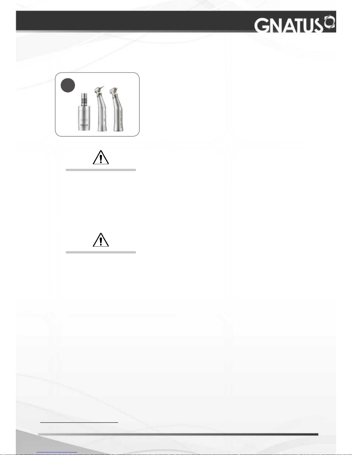
Description of Equipment
* Optional
IDENTIFICATION OF EQUIPMENT