55
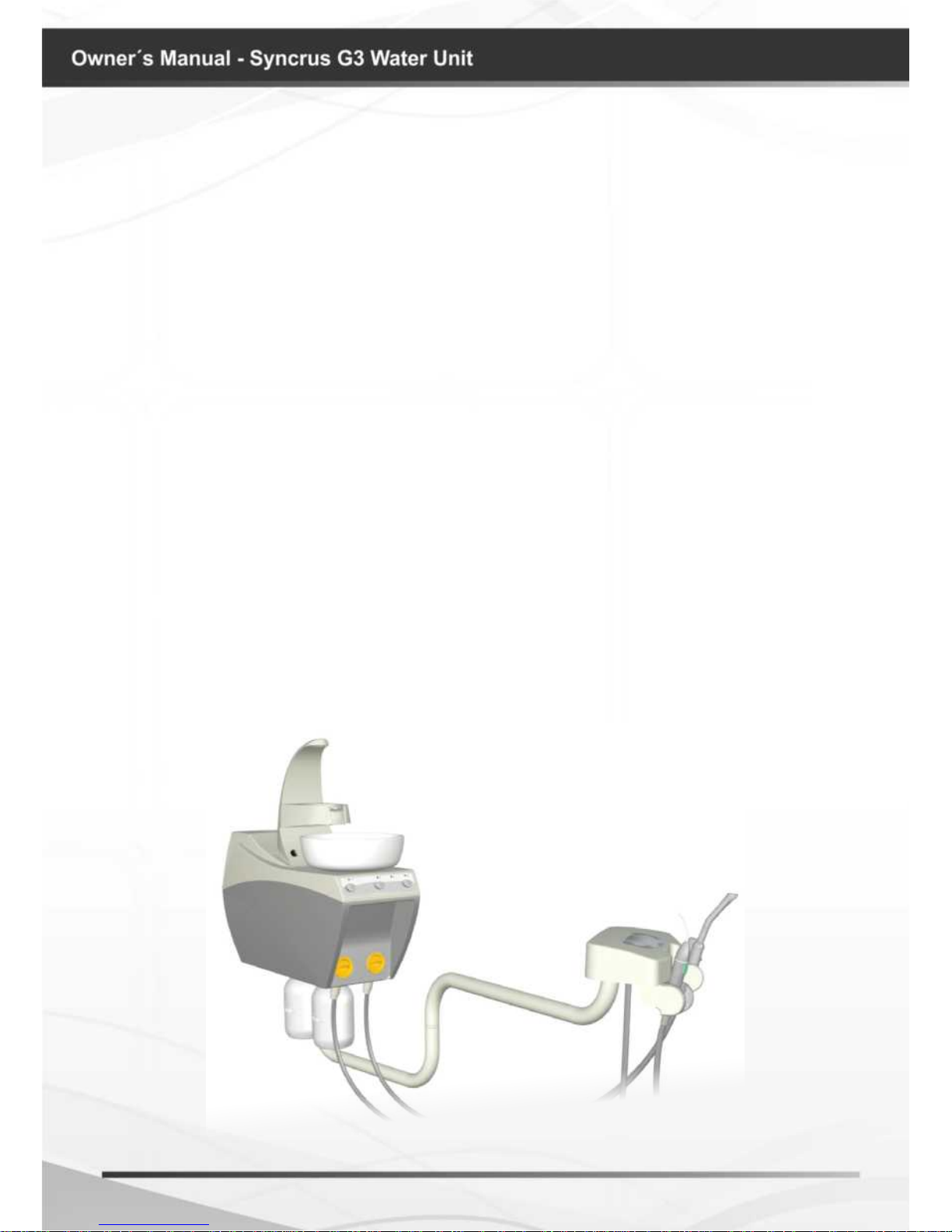
Water unit for dental use, for auxiliary works as water supply source and waste collection
from spitter bowl and sucking devices; ambidextrous (serves right and left-handed users),
attached to the chair, * actuated by optical sensor.
The frame is manufactured with steel structure, ABS injected body with anti-UV
protection. Smooth high glossy paint, epoxy-based, cured in an oven at 250° C, with
phosphate treatment resistant to rust, corrosion and cleaning chemicals.
Upper body of the unit conveniently located for better spitting position. Can be turned
60º, prioritizing ergonomics and allowing approach of the assistant.
Ceramic bowl spittoon, deep and easily removable for hygiene and asepsis, supplied
with strainer drain for solids retention.
Smooth hoses, rounded, soft and exible, without grooves or striations and quick connect
coupling that easily without the need for tools.
Stainless steel pipe to feed the water bowl, removable and autoclavable.
Has a debris lter easy to clean and disinfection.
Valve for water regulation in the tub and glass feeder.
* Electrical commands with timer for activating the water in the tub and glass feeder and
* Electrical controls for Bio-System drive and water heating in the triple syringe.
Automatic selection of tips through individual pneumatic valves, allowing light handling.
Suckers with automatic individual drive easy to use, they provide an excellent operating
performance, allow professionals to work with better visualization of the operative eld and
reduce the risk of contamination by aerosol and greater patient comfort.
* High power electric Suckers with individual low voltage drive, provide lightness and
accuracy in the drive.
* Triple syringe swivel spout, removable and autoclavable.
* Arm Reach: terminal support with wide horizontal movement that enables optimal
approach to the surgical eld and excellent accessibility to the various resources available.
Optimizes work prioritizing the ergonomics and biosafety.
Translucent water tanks for syringe * and * spray tips and chlorinated water * Bio-
System.
ISO 9001 and ISO 13485 Quality system, ensuring that products are manufactured
within standard procedures.
Products manufactured according to the RDC 16/13 - National Health Surveillance
Agency – ANVISA resolution.
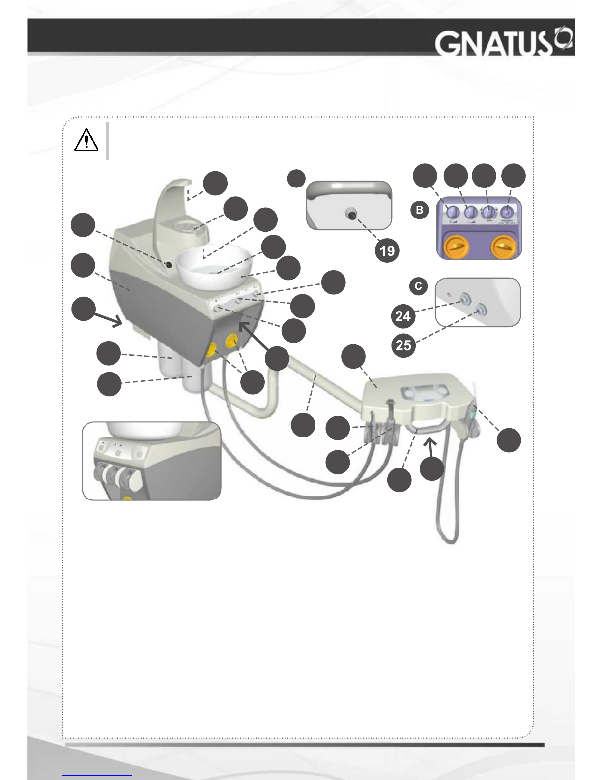
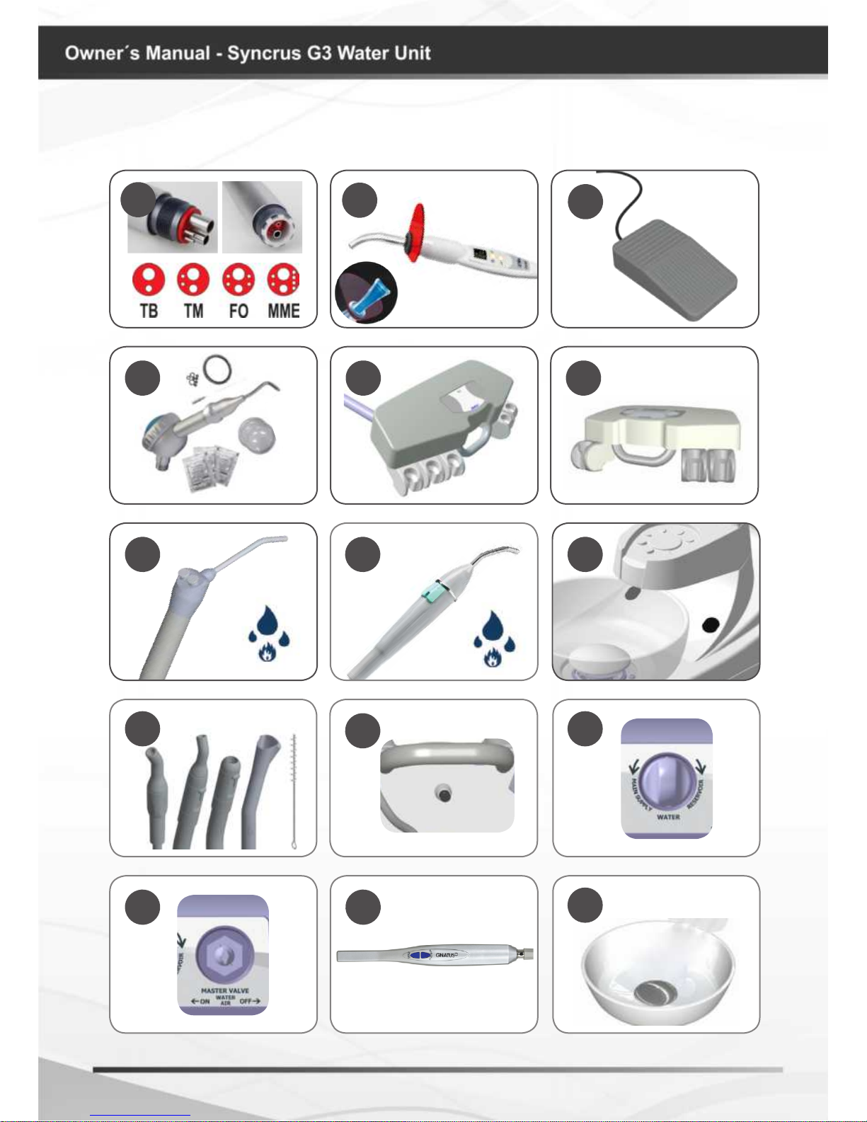
Description of Equipment
*Curing Light
Product Features:
Designed to carry out curing resin material through a curing process. The wavelength
of 440nm - 460nm associated with high energy emitted by Curing Light enables the multi-
functionality of this device.
It has high power LED with efcient coupling and optical distribution, providing speed
and security procedures. Ensures proper photo-activation of materials without wasting light.
The LED system of this machine has long service life, equivalent to 36 million 10-second
cycles without loss of power and efciency in the photo activation.
The reduced weight of the pen and its anatomical design ensure a more comfortable
and practical professional work.
Operation control with display and buttons on the pen itself.
Programmable operating time.
- 10, 20, 40, 60, 80 and 90 seconds with sound signal (beep) every 10 seconds.
* Optional
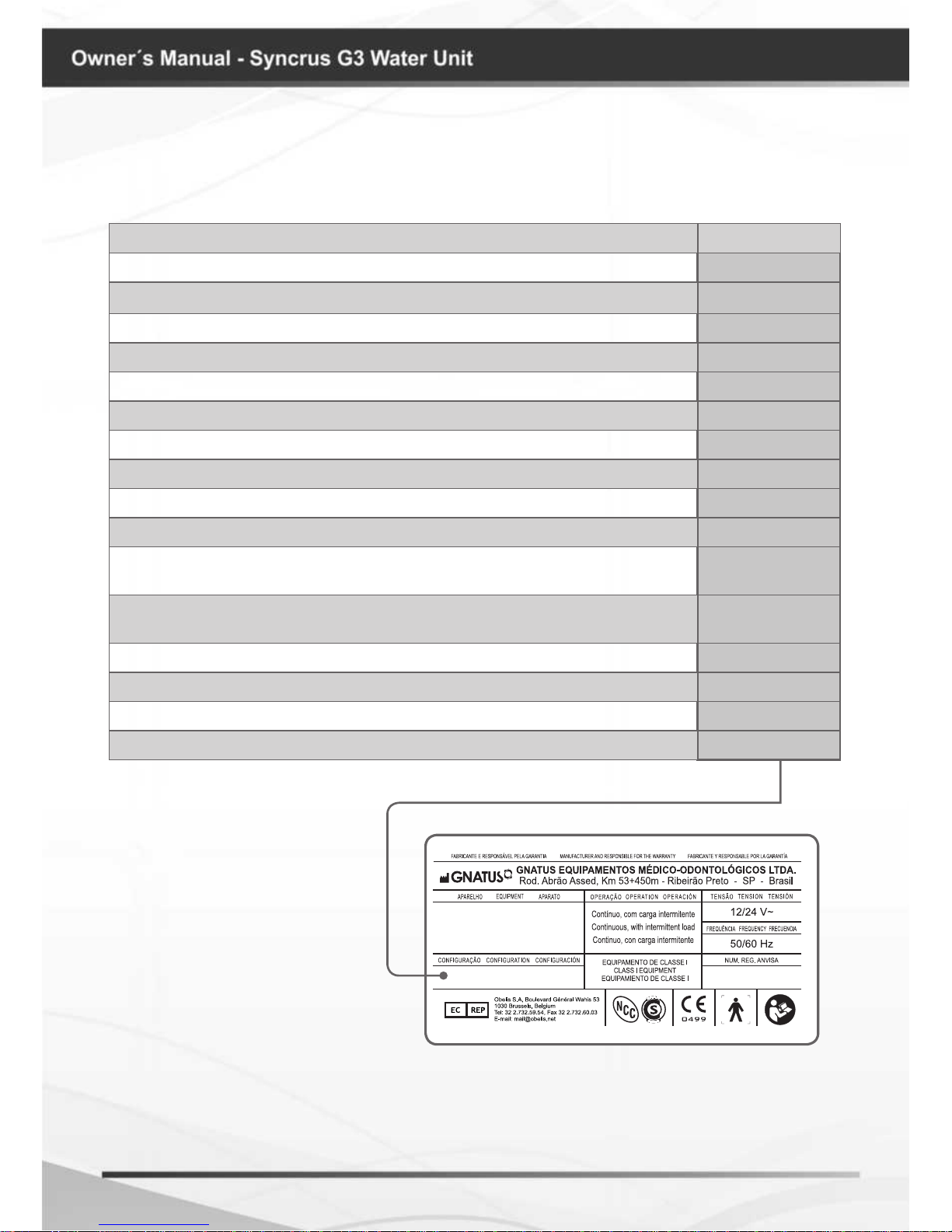
IDENTIFICATION OF EQUIPMENT