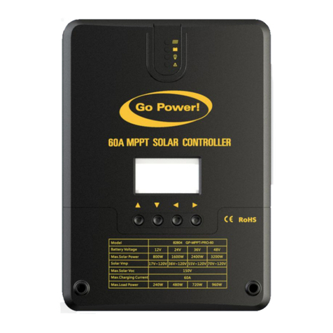
Go Power MPPT-PRO User manual

MPPT-PRO
Solar Controller
User Manual
GP-MPPT-PRO-40
© 2020 Go Power!
Worldwide Technical Support and Product Information gpelectric.com
Go Power!
201-710 Redbrick Street Victoria, BC, V8T 5J3
Tel: 1.866.247.6527
82803_MAN_GP-MPPT-PRO-40_RevA

Congratulations on purchasing your Go Power! MPPT Solar Controller.
Record the unit’s model and serial number below. It is much easier and quicker to record this information now at the pre-installation
stage.
Model Number:
Serial Number:
Date of Install:
Battery Bank Information: (size, install date, battery type)
Product Packaging
Please safely store the packing the IC Series was delivered in or recycle the packaging components as outlined
below:
LDPE
Low Density
Polyetheylene
CFB
3
4
7
CFB
3
4
7
CFB
3
4
7
CFB
3
4
7
CFB
3
4
7
Corrugated berboard
main box
Plastic
foam protection
Plastic
accessories bag
www.earth911.com/recycling-center-search-guides
Local recycling centeRs can be found here:
Corrugated
Recycles
www.corrugated.org
People. Planet. Prot.
Carmanah Technologies

gpelectric.com | [page 3]
CONTENTS
1. INTRODUCTION.......................................................................................................................5
1.1 SAFETY PRECAUTIONS .................................................................................................................................5
1.2 OVERVIEW.......................................................................................................................................................6
1.3 FEATURES .......................................................................................................................................................6
1.4 APPEARANCE..................................................................................................................................................7
1.5 MPPT TECHNOLOGY INSTRUCTIONS ..........................................................................................................8
1.6 CHARGING STAGE INSTRUCTIONS........................................................................................................... 10
2. INSTALLATION.......................................................................................................................11
2.1 TOOLS AND MATERIALS NEEDED...............................................................................................................11
2.2 INSTALLATION AND WIRING ....................................................................................................................... 12
3. PRODUCT OPERATION AND DISPLAY...............................................................................14
3.1 LED INDICATION........................................................................................................................................... 14
3.1.1 PV INDICATOR ................................................................................................................................... 14
3.1.2 BATTERY INDICATOR........................................................................................................................ 14
3.1.3 LOAD INDICATOR .............................................................................................................................. 15
3.1.4 ERROR INDICATOR........................................................................................................................... 15
3.2 KEYS OPERATION........................................................................................................................................ 15
3.3 LCD STARTUP AND MAIN INTERFACE ....................................................................................................... 15
3.3.1 STARTUP INTERFACE....................................................................................................................... 16
3.3.2 MAIN INTERFACE .............................................................................................................................. 16
3.4 LOAD MODE SETTING INTERFACE............................................................................................................ 17
3.4.1 LOAD MODE INTRODUCTION .......................................................................................................... 17
3.4.2 LOAD MODE ADJUSTMENT.............................................................................................................. 17
3.4.3 MANUAL MODE ON/OFF PAGE ........................................................................................................ 17
3.5 SYSTEM PARAMETER SETTINGS .............................................................................................................. 18
4. SYSTEM MAINTENANCE......................................................................................................19
4.1 ABNORMALITY DISPLAY AND WARNINGS................................................................................................. 19
5. TECHNICAL PARAMETERS..................................................................................................20
5.1 ELECTRICAL PARAMETERS......................................................................................................................... 20
5.2 BATTERY TYPE DEFAULT PARAMETERS ................................................................................................... 21
6. CONVERSION EFFICIENCY CURVE....................................................................................21
6.1 12V SYSTEMS............................................................................................................................................... 21
6.2 24V SYSTEMS............................................................................................................................................... 22
7. PRODUCT DIMENSIONS.......................................................................................................22
8. BLUETOOTH®DONGLES......................................................................................................23
8.1 PRODUCT INFORMATION ........................................................................................................................... 23
8.2 MAIN FEATURES .......................................................................................................................................... 23
8.3 LED STATUS ................................................................................................................................................. 23
8.4 APPLICABLE TYPE ...................................................................................................................................... 23
8.5 PRODUCT FEATURES ................................................................................................................................. 24
8.6 PRODUCT DIMENSIONS ............................................................................................................................. 24
8.7 SYSTEM WIRING DIAGRAM ....................................................................................................................... 25
8.8 SPECIFICATIONS ......................................................................................................................................... 25
www.earth911.com/recycling-center-search-guides
[page 4] | gpelectric.com
CONTENTS
9. REMOTE..............................................................................................................................26
9.1 PRODUCT FEATURES .......................................................................................................................... 26
9.2 APPEARANCE........................................................................................................................................ 26
9.3 INSTALLATION DIMENSIONS .............................................................................................................. 27
9.4 USAGE NAVIGATION KEYS ................................................................................................................. 27
9.5 LCD MENU .............................................................................................................................................28
9.5.1 ICON DESCRIPTION...................................................................................................................28
9.5.2 MENU BLOCK DIAGRAM............................................................................................................29
9.6 REAL-TIME MONITORING.....................................................................................................................30
9.7 SYSTEM PARAMETER SETTINGS .......................................................................................................31
9.7.1 CONTROLLER CHARGING AND DISCHARGING RELATED PARAMETER SETTINGS ..........32
9.7.2 LCD SCEEN BACKLIGHT TIME SETTING .................................................................................32
9.7.3 CONTROLLER ABNORMALITY VOICE ALARM – ON/OFF SETTING.......................................33
9.7.4 CLEAR HISTORICAL DATA AND RESET TO FACTORY SETTINGS.........................................33
9.8 LOAD MODES ........................................................................................................................................33
9.8.1 STATISTIC DATA..........................................................................................................................34
9.8.2 DEVICE INFORMATION ..............................................................................................................35
9.8.3 BLUETOOTH®CONNECTION STATUS......................................................................................36
9.8.4 COMMON PROBLEMS AND SOLUTIONS .................................................................................36
9.8 FAULT INDICATION AND COMMUNICATION INDICATION ..................................................................37

gpelectric.com | [page 5]
1.1 SAFETY PRECAUTIONS
Important safety information is contained throughout this manual that should be carefully observed and followed. This
information is presented using the following format.
The information is categorized in two ways:
Warning: Bodily harm could occur if instructions are not explicitly followed. If there are any doubts about the procedure or
conditions, please call GoPower! technical support before doing anything.
Caution: Damage to property could occur if instructions are not followed properly.
The following symbols are used to indicate the type of hazard.
GENERAL SAFETY
• Read entire manual before installation
•
Any voltage above 30 VDC should be considered dangerous. Make sure power is disconnected before touching
terminals that exceed this voltage.
•
There are no parts inside the controller that need to be maintained or repaired. The controller shall never be disassembled
• Unless otherwise specied, all terminal blocks should be re-tightened at least every 6 months to prevent possible re
caused by connections that have vibrated loose.
•
Ensure all connections are tight and secure. Loose connections may generate sparks and heat. Be sure to check
connections one week after installation to ensure they are still tight.
SOLAR CONTROLLER SAFETY
•
Always connect the battery BEFORE connecting the solar array to prevent damage to the controller. If the battery
wires need to be disconnected, the solar array wires should rst be disconnected.
•
To prevent damage to the controller, ensure the solar array voltage does not exceed the maximum voltage of the solar
controller. See specications table below to determine the limit for your controller.
BATTERY SAFETY
• Ensure the battery type is set correctly in the controller settings to avoid possible explosion or re
• Read manual for battery and observe safety precautions before connecting the battery to the controller
• Only use deep cycle batteries that are intended for energy storage applications
Warning / Caution: Result
Description of condition leading to result
1. INTRODUCTION
SYMBOL MEANING SYMBOL MEANING
General Warning Hot Surface
Risk of Shock Risk of Fire
Risk of Electrocution Risk of Chemicals
Risk of Explosion Risk of Eye Injury
SYMBOL

[page 6] | gpelectric.com
INTRODUCTION
1.2 OVERVIEW
This product can keep monitoring the solar panel’s generating power and tracking the highest voltage and current values
(VI) in real time, enabling the system to charge the battery in maximum power. It’s designed to be used in o-grid solar
photovoltaic systems to coordinate operation of the solar panel, battery and load, functioning as the core control unit in
o-grid photovoltaic systems.
This product features an LCD screen which can dynamically display the operating status, operating parameters, controller
logs, control parameters, etc. Users can conveniently check parameters by the keys and modify control parameters to
cater to dierent system requirements.
The controller utilizes standard Modbus communication protocol, making it easy for users to check and modify system
parameters on their own. Besides, by providing free monitoring software, we give users the maximum convenience to
satisfy their varied needs for remote monitoring.
With comprehensive electronic fault self-detecting functions and powerful electronic protection functions built inside the
controller, component damage caused by installation errors or system failures can be avoided to the greatest extent
possible
1.3 FEATURES
• Advanced dual-peak or multi-peak tracking technology, when the solar panel is shadowed or part of the panel fails
resulting in multiple peaks on the I-V curve, the controller is still able to accurately track the maximum power point.
• Built-in maximum power point tracking (MPPT) algorithm can signicantly increase energy utilization eciency of the
photovoltaic system, which is about 15% to 20% higher than traditional PWM charging.
• Provides an active charging voltage regulation feature. At battery open circuit or lithium battery BMS overcharge
protection, the controller battery terminal will output the rated charging voltage value.
• MPPT tracking eciency is up to 99.9%.
• Due to an advanced digital power technology, the circuit energy conversion eciency is as high as 98%.
• Available in multiple battery types and support charging procedures of various types of batteries such as lithium
battery, colloidal battery, sealed battery, vented battery, lithium battery, etc.
• A current-limited charging mode is available. When the power of solar panel is too large and the charging current
is higher than the rated valve, the controller automatically reduces the charging power so that the solar panel can
operate at the rated charging current.
• Supports automatic identication of lead-acid battery voltage.
• LED fault indicators and an LCD screen which can display abnormality information help users to quickly identify
system faults.
• Historical data storage function is available, and data can be stored for up to a year
• The controller is equipped with an LCD screen with which users can not only check device operating data and
statuses, but also modify controller parameters
• Support standard Modbus protocol to meet communication needs in dierent occasions.
• Built-in over-temperature protection mechanism ensures that when temperature exceeds the set value of the device,
the charging current decreases linearly with the temperature, thereby reducing the temperature rise of controller and
avoiding high temperature damage.
• Temperature compensation and automatic adjustment of charge and discharge parameters help to improve battery
life.
• Solar panel short circuit protection, battery open circuit protection and TVS lightening protection etc.

gpelectric.com | [page 7]
1.4 APPEARANCE
NO. NAME NO. NAME
1 Charging indicator 7 Battery “+”
2 Battery indicator 8 Battery “-”
3 Load indicator 9 Load “+”
4 Abnormality indicator 10 Load “-”
5 LCD screen 11 External temperature sensor
6 Operating keys 12 RS232 communication
interface
INTRODUCTION

[page 8] | gpelectric.com
INTRODUCTION
1.5 MPPT TECHNOLOGY INSTRUCTIONS
Maximum Power Point Tracking (MPPT) is an advanced charging technology that more eciently harvests power from
solar panels in all conditions. It does this by continuously tracking the I-V curve of the solar array and modifying operating
conditions to maximize output power. Figure 1-2 shows the MPPT point compared to a traditional PWM charger, which
always runs the solar array at the same operating conditions.
Due to dierences in ambient temperature and light conditions, the maximum power point often changes. The MPPT
controller can adjust parameters according to quickly changing conditions to keep the system near to its maximum
working point. The whole process is fully automatic and does not require any adjustments by users.
FIGURE 1-2 Solar panel output characteristics curve
FIGURE 1-3 Relationship between solar panel output characteristics and light

gpelectric.com | [page 9]
In partially shaded conditions there can also be multiple peaks in the P-V curve that can confuse an MPPT algorithm.
Shown in Figure 1-5 is a series string of solar panels and a corresponding graph that shows lower maximum power points
(LMPP) and the greater maxim power point (GMPP) that will result in maximum energy transfer. The GP-MPPT-PRO
series has a smart algorithm that will always choose the right peak.
INTRODUCTION
FIGURE 1-4 Relationship between solar panel output characteristics and temperature
(A)
40

[page 10] | gpelectric.com
1.6 CHARGING STAGE INTRODUCTIONS
Maximum power point tracking is used to charge the batteries with the highest current possible, but this is only part of the
equation. A battery cannot be charged at maximum power all the time for safety reasons, so multiple stages are used.
These stages include bulk, boost, oat and, for some types of batteries,
equalization as shown in Figure 1-6.
FIGURE 1-5 Multiple peaks resulting from partial shading
(B)
FIGURE 1-6 Battery charging stages curve graph

gpelectric.com | [page 11]
STAGE 1: BULK
In quick charge stage, the battery voltage has not yet reached the set value of full charge voltage (i.e. equalizing/boost
charge voltage) and the controller will perform MPPT charging, which will provide maximum solar energy to charge the
battery. When the battery voltage reaches the pre-set value, Stage 2 charge will start.
STAGE 2: BOOST
When the battery voltage reaches the boost voltage, the controller will perform constant voltage charging. This is no
longer MPPT charging, and the charging current will gradually decrease with time.
STAGE 3: FLOAT
Float charge is conducted following the boost charge stage. The controller will reduce the charge current to a small
amount in order to prevent self-discharge of the battery and keep it fully charged. If the load exceeds this small current
the battery voltage will start to decrease until it reaches the recharge voltage. When the battery voltage falls below the
recharge voltage, the controller will switch back to bulk charging.
STAGE 4: EQUALIZE
Warning: Risk of explosion!
Equalizing vented lead-acid battery may generate explosive gases. So, the battery
compartment must be well ventilated.
Caution: Damage of device!
Equalization can increase the battery voltage to levels that may damage sensitive DC loads.
It is necessary to verify that the allowable input voltage of all system loads is greater than the
equalizing charge set value.
Caution: Damage of device!
Over charge and excessive gas evolution may damage the battery plates and cause active
substances on the battery plate to come o. Equalizing charge may cause damage if voltage
is too high or time is too long. Please carefully check the specic requirements of battery
used in the system.
Certain types of battery benet from regular equalizing charge, which can stir electrolyte, balance battery voltage,
and complete chemical reaction. The equalize charge increases the battery voltage above standard voltage, causing
vaporization of battery electrolyte. By default, this happens every 28 days.
When the controller is not able to stabilize battery voltage due to the inuence of installation environment or
load, the controller will wait for 3 hours (or custom value if custom battery type used) and then automatically
switch to oat charge
2. INSTALLATION
Now that you are ready to begin installing your new solar controller, please ensure you have read all safety precautions in
section 1.1 of this manual and then proceed with the following instructions.
2.1 TOOLS AND MATERIALS NEEDED
• Screwdriver.
• Multimeter
If the solar controller was purchased with a Go Power! RV Solar Power Kit the UV resistant wire is included.
For instructions regarding the Go Power! RV Solar Power Kit installation, please refer to the installation
guide provided with the kit
Note
Note
2. INSTALLATION

[page 12] | gpelectric.com
INSTALLATION
2.2 INSTALLATION AND WIRING
STEP 1: CHOOSE AN INSTALLATION LOCATION
The GP-MPPT-PRO controllers are designed to be mounted vertically in a battery box with sucient ventilation and
should be as close to the battery as possible. Adequate space above and below the controller is vitally important to ensure
proper natural convection for heat dissipation as shown below. Avoid installing the controller in a place with direct sunlight,
high temperature, and/or water.
STEP 2: MARK THE MOUNTING POSITION ACCORDING TO THE MOUNTING DIMENSIONS OF THE CONTROLLER.
First, place the installation guide plate at a proper position and use a marking pen to mark the mounting points. Drill 4
mounting holes of the appropriate size at the 4 marks. Fix screws into the upper two mounting holes.
STEP 3: FASTEN THE CONTROLLER
Align xing holes of the controller with the two pre-xed screws and hang the controller up. And then x the lower two
screws.
STEP 4: WIRING
Wiring and installation must comply with national and local electrical code requirements.
The wire from the solar array most commonly enters the RV through the fridge vent on the roof or by using the Go Power!
Cable Entry Plate (sold separately) that allows installers to run wires through any part of the roof. PV connections should
connect directly to the controller.
Positive and negative battery connections must connect directly from the controller to the batteries and positive and
negative PV connections must connect directly from the solar array to the controller. Wires that are as short as possible
and adequately sized (see table below) should always be used. Use of a positive and/or negative distribution bus that is
properly sized is recommended between the controller and battery – do not stack wires on the battery terminals.

gpelectric.com | [page 13]
Warning: Danger, Electric shock hazards! We strongly recommend connect a fuse or circuit
breaker to the PV array and battery terminals to prevent electric shock hazards during wiring
or error operation, and make sure that fuse or circuit breaker is disconnected before wiring.
Models PV maximum input
current
Max. wire diameter
at PV end
(mm²/AWG)
Rated charge current Battery wire diameter
(mm²/AWG)
GP-MPPT-PRO-30 30 8/8 30A 8/8
GP-MPPT-PRO-40 40 10/7 40A 10/
GP-MPPT-PRO-50 50 12/6 50A 12/6
GP-MPPT-PRO-60 60 60A
For installation safety, we recommend a wiring sequence as follows; however, wiring in other sequence instead of this one
will not damage the controller.
1) Note that the battery fuse shall be installed as close as possible to the battery terminal. The
recommended distance is not more than 150mm.
2) The battery temperature is 25°C (xed value) when the controller is not collected to a remote temperature
sensor.
Note
INSTALLATION

[page 14] | gpelectric.com
3.1 LED INDICATION
There are four indicators on the controller.
PV Array Indicator Indicating the controller’s current
charging mode
BAT Indicator Indicating the battery’s current state
LOAD Indicator Indicating the load’s ON/OFF and state
ERROR Indicator Indicating whether the controller is
functioning normally
3.1.1 PV INDICATOR
LED PATTERN STATUS
STEADY ON MPPT CHARGING
SLOW FLASH
(cycle of 2s with on and o each lasting for 1s) BOOST CHARGING
SINGLE FLASH
(cycle of 2s with on and o lasting respectively for 0.1s and 1.9s) FLOAT CHARGING
QUICK FLASH
(cycle of 0.2s with on and o each lasting for 0.1s) EQUALIZE CHARGING
DOUBLE FLASH
(cycle of 2s with on for 0.1s, o for 0.1s, on again for 0.1s, and o again for 1.7s) CURRENT LIMITING
OFF NO CHARGE
3.1.2 BATTERY INDICATOR
LED PATTERN STATUS
STEADY ON NORMAL BATTERY CHARGE
SLOW FLASH
(cycle of 2s with on and o each lasting for 1s) BATTERY OVER-DISCHARGED
QUICK FLASH
(cycle of 0.2s with on and o each lasting for 0.1s) BATTERY OVER-VOLTAGE
3. PRODUCT OPERATION AND DISPLAY

gpelectric.com | [page 15]
PRODUCT OPERATION AND DISPLAY
4. SYSTEM MAINTENANCE
3.1.3 LOAD INDICATOR
LED PATTERN STATUS
OFF LOAD TURNED OFF
QUICK FLASH
(cycle of 0.2s with on and o each lasting for 0.1s) LOAD OVER-LOADED/SHORT-CIRCUITED
STEADY ON LOAD FUNCTIONING NORMALLY
3.1.4 ERROR INDICATOR
LED PATTERN STATUS
OFF SYSTEM OPERATING NORMALLY
STEADY ON SYSTEM MALFUNCTIONING
3.2 KEY OPERATIONS
3.3 LCD STARTUP AND MAIN INTERFACE
▲ UP Page up; increase the parameter value in setting
▼ DOWN Page down; decrease the parameter value in setting
◄ RETURN Return to previous menu (exit without saving)
► SET Enter into sub-menu; set/ save
Turn on/ o loads (in manual mode)
NIGHTTIME
CHARGING
STAGE
SETTING BLUETOOTH BATTERY
TYPE
ABNORMALITY UNIT
SOLAR PANEL BATTERY
PARAMETER
VALUE
LOAD
DAYTIME
SYSTEM
VOLTAGE
SERIAL
PORT
CHARGING DISCHARGING

[page 16] | gpelectric.com
PRODUCT OPERATION AND DISPLAY
3.3.1 STARTUP INTERFACE
During startup, the 4 indicators will rst ash successively, and after self-inspection, the LCD screen starts and displays
the battery’s voltage level which will be either a xed voltage selected by the user or a voltage automatically recognized
3.3.2 MAIN INTERFACE
MAIN
MONITORING PAGE COMPONENT VOLTAGE CHARGING CURRENT
BATTERY VOLTAGE
LOAD CURRENT
DEVICE TEMPERATURE
ABNORMALITY CODE
LOAD MODE
BATTERY CAPACITY
CHARGING CAPACITY
DISCHARGING CAPACITY

gpelectric.com | [page 17]
3.4 LOAD MODE SETTING INTERFACE
3.4.1 LOAD MODES INTRODUCTION
No. Mode Description
0Sole light control (night-
time on and daytime o)
When no sunlight is present, the solar panel voltage is lower than the light
control on voltage, and after a time delay, the controller will switch on the load;
when sunlight emerges, the solar panel voltage will become higher than the light
control o voltage, and after a time delay, the controller will switch o the load.
1 to 14 Light control + time control
1 to 14 hours
When no sunlight is present, the solar panel voltage is lower than the light con-
trol on voltage, and after a time delay, the controller will switch on the load. The
load will be switched o after working for a preset period of time.
15 Manual mode
In this mode, the user can switch the load on or o by the keys, no matter wheth-
er it’s day or night. This mode is designed for some specially purposed loads,
and also used in the debugging process.
16 Debugging mode
Used for system debugging. With light signals, the load is shut o; without light
signals, the load is switched on. This mode enables fast check of the correctness
of system installation during installation debugging.
17 Normal on mode The energized load keeps outputting, and this mode is suitable for loads which
need 24-hour power supply.
3.4.2 LOAD MODE ADJUSTMENT
Users can adjust the load mode as needed on their own, and the default mode is debugging mode (see “load modes
introduction”). The method for adjusting load modes is as follows:
3.4.3 MANUAL LOAD ON/OFF PAGE
Manual operation is eective only when the load mode is manual mode (15) and tap the Set key to switch on/ o the load
under any main interface.
PRODUCT OPERATION AND DISPLAY
LOAD MODE
Press and hold the SET key
to enter
Tap the UP or
DOWN key to
set the mode
Tap the RETURN
key to exit without
saving
Tap and hold the SET key to
save and exit

[page 18] | gpelectric.com
3.5 SYSTEM PARAMETER SETTINGS
Under any interface other than load modes, press and hold the Set key to enter into the parameter setting interface.
After entering into the setting interface, tap the Set key to switch the menu for setting, and tap the Up or Down key to increase
or decrease the parameter value in the menu. Then tap the Return key to exit (without saving parameter setting) or press
and hold the Set key to save setting and exit.
After system voltage setting, power supply has to be switch o and then on again, otherwise
the system may work under an abnormal system voltage.
The controller enables users to customize the parameters according to the actual conditions, but parameter setting must
be done under the guidance of a professional person, or else faulty parameter settings may render the system not able to
function normally. For details about parameter settings, see table 3.
No. Display Item Description Parameter Range Default Setting
1 TYPE OF BAT Battery type User/ooded/Sealed/Gel/Li Sealed
2 VOLT OF SYS System voltage 12V/ 24V AUTO
3 EQUALIZ CHG Equalizing charging
voltage 9.0 to 17.0V 14.6V
4 BOOST CHG Boost charging voltage 9.0 to 17.0V 14.4V
5 FLOAT CHG Floating charging voltage 9.0 to 17.0V 13.8V
6 LOW VOL RECT Over-discharge recovery
voltage 9.0 to 17.0V 12.6V
7 LOW VOL DISC Over-discharge voltage 9.0 to 17.0V 11.0V
BATTERY TYPE
OVER-DISCHARGE
OVER-DISCHARGE
RETURN
FLOATING CHARGING
VOLTAGE
SYSTEM VOLTAGE EQUALIZING VOLTAGE BOOST VOLTAGE
Table 3
Note
PRODUCT OPERATION AND DISPLAY

gpelectric.com | [page 19]
In order to maintain the best long-term performance for controller, it is recommended to conduct inspections twice a year
using the following points:
• Make sure the airow around the controller is not obstructed and remove any dirt or debris from the heat sink.
•
Check if the insulation layers of all exposed wires are damaged due to sun exposure, friction with other objects nearby,
dry rot, destruction of insects or rodents, etc. If so, it is necessary to repair or replace the wire.
•
Verify if indicators are consistent with the device operations. Please note to take corrective actions for any malfunctions
or error indications if necessary.
•
Check all wiring terminals for corrosion, insulation damage, signs of high temperature or burning/discoloration. Tighten
terminal screws.
• Check for dirt, insects nesting and corrosion and clean as required.
Warning: Danger, electric shock hazards! Make sure that all power supplies to the controller
have been disconnected before check or operation as above
4.1 ABNORMALITY DISPLAY AND WARNINGS
No. Error Display Description LED Indication
1 E0 No abnormality ERROR indicator o
2 E1 Battery over-discharge BAT indicator ashing slowly
ERROR indicator steady on
3 E2 System over-voltage BAT indicator ashing quickly
ERROR indicator steady on
4 E3 Battery under-voltage warning ERROR indicator steady on
5 E4 Load short circuit LOAD indicator ashing quickly
ERROR indicator steady on
6 E5 Load overloaded LOAD indicator ashing quickly
ERROR indicator steady on
7 E6 Over-temperature inside controller ERROR indicator steady on
8 E7 Photovoltaic component overloaded ERROR indicator steady on
9 E8 Photovoltaic component over-voltage ERROR indicator steady on
10 E9 Photovoltaic component reversely con-
nected ERROR indicator steady on
4. SYSTEM MAINTENANCE

[page 20] | gpelectric.com
5.1 ELECTRICAL PARAMETERS
ITEMS PARAMETERS
MODEL GP-MPPT-PRO-30 GP-MPPT-PRO-40 GP-MPPT-PRO-50 GP-MPPT-PRO-60
SYSTEM VOLTAGE 12V/24V
ZERO LOAD LOSS <10mA
BATTERY VOLTAGE 9V~32V
MAXIMUM PV OPEN
CIRCUIT VOLTAGE 92V(25˚C); 100V(Lowest Ambient Temperature)
MAXIMUM POWER
POINT VOLTAGE
RANGE
(Battery voltage +2V) ~ 72V
RATED CHARGING
CURRENT 30A 40A 50A 60A
MAXIMUM PV INPUT
POWER
400W/12V
800W/24V
550W/12V
1100W/24V
660W/12V
1320W/24V
CHARGING
CONVERSION
EFFICIENCY
≤98%
MPPT TRACKING
EFFICIENCY >99%
TEMPERATURE
COMPENSATION
COEFFICIENT
-3mv/˚C/2V (default); Lithium battery features no temperature compensation
OPERATING
TEMPERATURE -35˚C ~ +45˚C
IP RATING IP32
WEIGHT 700g 800G 900G
COMMUNICATION
MODE TTL Serial communication
ALTITUDE ≤ 3000 meters
DIMENSIONS 150*105.6*67.5 183*127*65.5 183*127*69.5
5. TECHNICAL PARAMETERS
Table of contents
Other Go Power Controllers manuals

Go Power
Go Power GP-DURALITE-100 User manual

Go Power
Go Power GP-PWM-30-SB User manual

Go Power
Go Power GP-PWM-10-FM User manual

Go Power
Go Power GPR-25 User manual

Go Power
Go Power GP-MPPT-85/20 User manual

Go Power
Go Power DOMETIC GP-BMG User manual

Go Power
Go Power MAXIMUM GP-PWM-10 User manual

Go Power
Go Power 10 AMP RVC-MPPT User manual

Go Power
Go Power GP-PWM-10 User manual

Go Power
Go Power GP-PWM-30-UL User manual