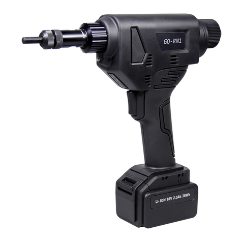
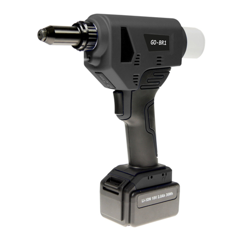
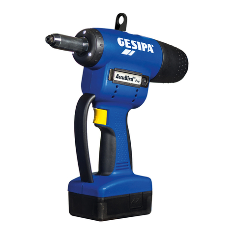
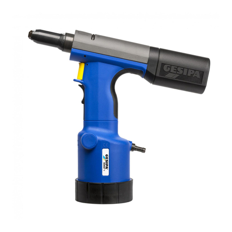
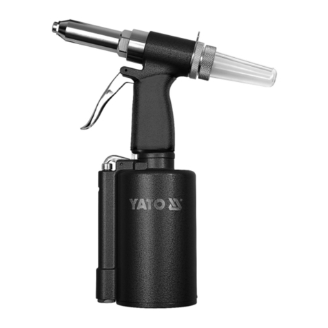
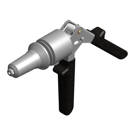
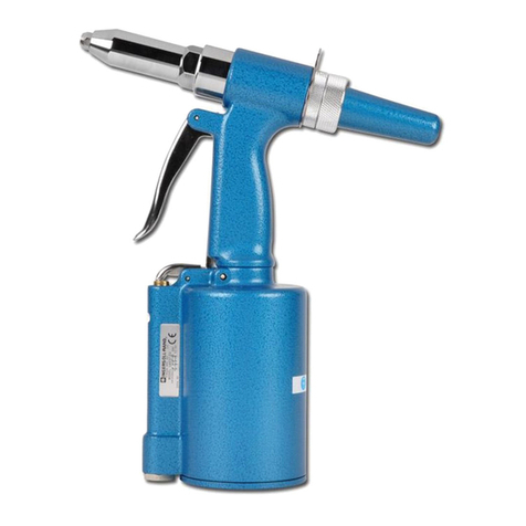
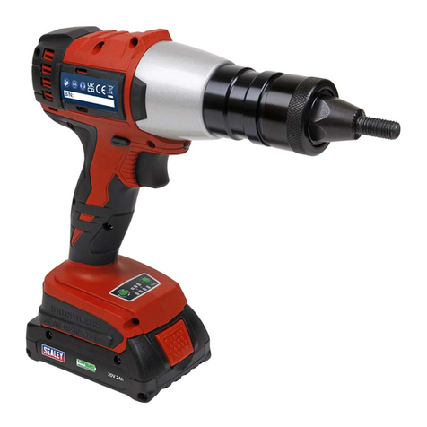
GOEBEL GO-100 User manual

GO-100 GO-100+ GO-200
Manual
w w w . g o e b e l - g r oup.com
UL
®


Manual Goebel
GO-100, GO-100+ and GO-200
Battery-powered Riveting Tools
1. Battery-powered Riveting Tool 4
1.1 Work Capacity 4
1.2 Equipment and Accessories 4
1.3 Technical Data 6
1.4 Parts List 7
2. Operation Instructions 10
2.1 Starting instruction 10
2.2 Operating instruction 10
2.3 Trouble Shooting 11
3. Battery and Charger 12
3.1 Technical Data 12
3.2 Battery Charging and Safety Instructions 12
3.2.1 Charging 12
3.2.2 Battery Safety Instructions 13
3.2.3 Charger Safety Instructions 13
4. Maintenance and Service 13
4.1 Maintenance 13
4.2 Service 14
5. Operation Safety Instructions 14
15
6.1 Warranty 15
16
17
GO-100 fig. B
GO-100+ fig. A
GO-100+ fig. B
GO-200 fig. A
18
19
20
3
21
22

1. Battery-powered Riveting Tools
1.1 Work Capacity
Model GO-100 for standard blind rivets all materials dia 3/32“ up to 3/16“
(2.4 mm up to 5.0 mm).
Model GO-200 for high strength blind rivets all materials dia 5/32“ up to 1/4“
(4.0 mm up to 6.4 mm).
(When setting rivets dia 3/32“ up to 1/8“ (2.4 mm up to 3.2 mm) with GO-200,
relevant nose pie
ces and push pin set should be purchased separately
1.2 Equipment and Accessories
1. nose pieces 2. front sleeve
3. hook 4. power illustration
5. mandrel collector 6. warning light
7. trigger 8. battery
9-11. accessories
Accessories
• Nose piece (2.4mm)blind rivets, stored in toolkit
• Nose piece (3.0/3.2mm)blind rivets,
stored in tool kit
• Nose piece C – for riveting dia. 5/32“ (4.0mm)blind rivets, stored in tool kit
• Nose piece D – for riveting dia. 3/16“ (4.8/5.0mm) blind rivets equipped on
tool
• Wrench – for nose pieces changing
• Battery charger set
• Battery(s) 14.4V 1,4Ah/4-cell or/and 14.4V 2,8Ah/8-cell
4
and replaced on tool)
A - for riveting dia 3/32“
B - for riveting dia 1/8“
Model GO-100+ for Triple Claw Blind Rivets dia 3/16“ up to 9/32“
(5.2 mm up to 7.5 mm)

1. nose pieces 2. front sleeve
3. hook 4. power illustration
5. mandrel collector 6. warning light
7. trigger 8. battery
9-15. accessories 16. 3-jaw set
5
Model GO-100+ Refer to GO-100+ fig. A
1. nose pieces 2. front sleeve
3. hook 4. power illustration
5. mandrel collector 6. warning light
7. trigger 8. battery
9-10. accessories
• Nose piece 22 – for riveting dia 3/16“ (5.2 mm) triple claw blind rivets,
equipped on tool
• Nose piece 23 – for riveting dia 1/4“ (6.4 mm) triple claw blind rivets,
stored in tool kit
• Nose piece 24 – for riveting dia 9/32“ (7.5 mm) triple claw blind rivets,
stored in tool kit
• Wrench – for nose pieces changing
• Battery charger set
• Battery(s) 14.4V 1.1 Ah/4-cell or/and 14.4V 2.8Ah/8-cell
Accessories
Accessories
• Nose piece C - for riveting dia. 5/ 32“ ( 4.0 mm) blind rivets, stored in tool kit
• Nose piece D - for riveting dia. 3/16“ (4.8/5.0 mm) blind rivets; stored in tool kit
• Nose piece E – for riveting dia. .2 36“(6 .0 mm) blind rivets, stored in tool kit
• Nose piece F – for riveting dia. 1/ 4“ (6 .4m m) blind rivets, equipped on tool
• Nose piece G – for M-LOCK 3/16“ (4.8 mm) structural rivets, stored in tool kit

1.3 Technical Data
Model GO-100
Tool weight 4,52 lbs (2,05 kg) (incl. 4-cell battery)
Stroke 20 mm (787” )
Drive unit 14,4V direct current motor
Traction power >12,000N (2,247 lbs)
Model GO-200
Tool weight 4,52 lbs (2,05 kg) (incl. 4-cell battery)
Stroke 27 mm (1.063” )
Drive unit 14,4V direct current motor
Traction power >18,000N (4,045 lbs)
6
Model GO-100+
Tool weight 4,52 lbs (2,05 kg) (incl. 4-cell battery)
Stroke 20 mm (787” )
Drive unit 14,4V direct current motor
Traction power >12,000N (2,247 lbs)
• Nose piece H – for PREMIUM and H-LOCK 3/16“ (4.8 mm) high strength
blind rivets, stored in tool kit
• Nose piece J – for M-LOCK 1/4“ ( 6.4 mm) high strength blind rivets,
stored in tool kit
• Nose piece K – for PREMIUM and H-LOCK 1/4“ (6.4 mm)
high strength blind rivets, stored in tool kit
• Wrench – for nose pieces changing
• Battery charger set
• Battery(s) 14.4V 1,4V 1,4Ah/4-cell or/and 14.4V 2,8Ah/8 -cell

1.4 Parts List
Position art. code parts description quantities on tool
1 22660 00036 Nosepiece 22 3/16“ 1
2 22660 00017 Front Sleeve Set 1
3 22660 00018 Clamping Sleeve 1
4 22660 00019 3-jaw Set 1
5 22660 00020 Push Pin Set 1
6 22660 00021 Push-pin Spring 1
7 22660 00022 Spring Sleeve Set 1
8 22660 00047 Flat Cross Head Screws 2
9 22660 00064 Power Illustration 1
10 22660 00065 Power Illustration Cable 1
11 22660 00060 Tool Body Set Goebel GO-100 1
12 22660 00042 Mandrel Release Tube 1
13 22660 00052 Mandrel Collector 1
14 22660 00045 PCB Set 1
15 22660 00059 Gear Box Set 1
16 22660 00053 Motor 1
17 22660 00055 Machine Screws 2
18 22660 00056 Li-Ion Battery 14,4V 1,4Ah/4-cell 1
19 22660 00057 Li-Ion Battery 14,4V 2,8Ah/8-cell 1
20 22660 00158 Battery Charger Set 1
21 22660 00029 Wrench 1
22 22660 00077 Nosepiece 23 1/4“ 1
23 22660 00078 Nosepiece 24 9/32“ 1
7
(5,2mm)
(7.5mm)
(6.4mm)
+

1.4 Parts List
Position art. code parts description quantities on tool
1 22660 00036 Nosepiece 22 3/16“ 1
2 22660 00017 Front Sleeve Set 1
3 22660 00018 Clamping Sleeve 1
4 22660 00019 3-jaw Set 1
5 22660 00020 Push Pin Set 1
6 22660 00021 Push-pin Spring 1
7 22660 00022 Spring Sleeve Set 1
8 22660 00047 Flat Cross Head Screws 2
9 22660 00064 Power Illustration 1
10 22660 00065 Power Illustration Cable 1
11 22660 00060 Tool Body Set Goebel GO-100 1
12 22660 00042 Mandrel Release Tube 1
13 22660 00052 Mandrel Collector 1
14 22660 00045 PCB Set 1
15 22660 00059 Gear Box Set 1
16 22660 00053 Motor 1
17 22660 00055 Machine Screws 2
18 22660 00056 Li-Ion Battery 14,4V 1,4Ah/4-cell 1
19 22660 00057 Li-Ion Battery 14,4V 2,8Ah/8-cell 1
20 22660 00158 Battery Charger Set 1
21 22660 00029 Wrench 1
22 22660 00077 Nosepiece 23 1/4“ 1
23 22660 00078 Nosepiece 24 9/32“ 1
8
(5.2mm)
(7.5mm)
(6.4mm)
+

1.4 Parts List
position art. code part description quantities on tool
1 22660 00069 Nosepiece F (6.4 mm) 1
2 22660 00017 Front Sleeve Set 1
3 22660 00018 Clamping Sleeve 1
4 22660 00048 3-jaw Set for 6.4 mm 1
5 22660 00049 Push Pin Set 1
6 22660 00021 Push-pin Spring 1
7 22660 00067 Spring Sleeve Set for 1/4“ 1
8 22660 00047 Flat Cross Head Screws 2
9 22660 00064 Power Illustration 1
10 22660 00065 Power Illustration Cable 1
11 22660 00061 Tool Body Set Goebel GO-200 1
12 22660 00051 Mandrel Release Tube 1
13 22660 00052 Mandrel Collector 1
14 22660 00046 PCB Set 1
15 22660 00062 Gear Box Set 1
16 22660 00054 Motor 1
17 22660 00055 Machine Screws 2
18 22660 00056 Li-Ion Battery 14,4V 1,4Ah/4-cell 1
19 22660 00057 Li-Ion Battery 14,4V 2,8Ah/8-cell 1
20 22660 00158 Battery Charger Set 1
21 22660 00029 Wrench 1
22 22660 00019 3-jaw Set for 3/32“-3/16“ 1
23 22660 00073 Nosepiece K for PREMIUM/H-LOCK 1/4“ 1
24 22660 00072 Nosepiece J for M-LOCK 1/4“ 1
25 22660 00071 Nosepiece H for PREMIUM/H-LOCK 3/16“ 1
26 22660 00070 Nosepiece G for M-LOCK 3/16“ 1
27 22660 00068 Nosepiece E .236“ 1
28 22660 00316 Nosepiece D 3/16“ 1
29 22660 00532 Nosepiece C 5/32“ 1
9
(1/4“)
(2.4-5.0mm)
(6,4 mm)
(6.4mm)
(6.4mm)
(4.8mm)
(4.8mm)
(6.0mm)
(4.8/5.0mm)
(4.0mm)

2. Operating Instructions
2.1 Starting instructions
Install battery on tool, check battery power on power indication:
4 LED lights on, power 95% ±5%;
3 LED lights on, power 75% ±5%;
2 LED lights on, power 50% ±5%;
1 LED light on, power 25% ±5% remaining,
charging battery is recommended.
During tool operation, press the button on power indication and the remai-
ning power is shown.
- Choose correct nose piece and it onto the tool
(see 1.2)
- Ensure that vent holes on the tool body are not covered or
obstructed
- Ensure that the mandrel collector is installed onto the tool
2.2 Operating instruction
- Insert the rivet mandrel fully into the nose piece, install it onto the
work piece, start the operation by depressing the trigger.
- After the rivet is set, release the trigger and the jaw assembly of the
tool returns to the start position automatically.
- Eject the rest mandrel by tilting to the rear into the mandrel
collector, or to the front through the nose piece.
- The tool is equipped with overload protection.
In the event of an overload, the operation will be stopped and the
warning light shows. Release the trigger and the jaw assembly will
return to the start position.
10
11
2.3 Trouble Shooting
2.3.1 Blind rivet cannot be set
Troubles and Causes Remedy
When depressing the trigger, 4 LED
power indication lights blink in rotation,
indicating low power
Charge battery
Battery damaged Change battery
Jaw assembly loose Tighten the assembly (see 4.)
2.3.2 No rest mandrel discharge
Troubles and Causes Remedy
Wrong nose piece Change to correct nose piece
Nose piece worn Replace nose piece
Rest mandrel jammed in clamps Loosen the mandrel, clean the clamps
assembly and lubricate them
Mandrel collector full Discharge the mandrel collector and
empty
Mandrel release tube blocked Remove the mandrel and check for
ejection
2.3.3 Warning light indicates faults
Troubles and Causes Remedy
Clamps not return to the start position Release the trigger
Overloading Check the rivet as per tool working
capacity
Overheating Cool off the tool in the air
Battery empty Charge the battery, or replace when
needed
NOTE In case of remedy measures do not work as described above, the tool has to be
repaired by skilled personnel or to be returned to the distributor or manufacturer’s agent.

3. Battery and Charger
3.1 Technical Data
Battery
Nominal voltage:
Cell: Li-ion
Number of cells: 4/8
Capacity: 1,4Ah/2,8Ah
Weight: 1,30 lbs (0,35 kg / 0,59 kg)0,77 lbs/
Charger
Input voltage: 100–240VAC/50-60Hz
Output voltage: 14,4 VDC
Output current: 1,5A max.
Weight:
3.2 Battery Charging and Safety Instructions
3.2.1 Charging
Charge only Goebel batteries supplied by authorized distributors.
To have the charger connected to proper power supply, insert the battery
onto the charger.
The Goebel Li-ion battery is protected against deep discharge by the “Electro-
nic Cell Protection, (ECP)”. When the battery is empty, the tool is switched off
by means of a protective circuit. LED lights on the power illustration will blink
in rotation indicating the battery needs to be charged.
During the process of charging, light blinks green.
Light steady green, indicates the battery is charged.
Light steady red, indicates the charging temperature out of range (0°C~45°C)
and charging must be terminated.
Light blinks red, check the condition of the power plug, if still blinking red, it
indicates the battery is damaged, charging must be terminated.
12
14,4VDC
1,04 lbs (0,47 kg)

3.2.2 Safety Instructions
- The battery should be removed from the tool when the tool is
stored or will not be used for a long period of time.
- Never try to charge a damaged battery.
- Do not insert a dirty or wet battery into the charger.
- Never throw batteries into the waste, into into water.
- Do not charge a battery when the environmental temperature is
below 0°C or higher than 45°C.
3.2.3 Charger Safety Instructions
- Make sure that the charger and its power connection equipment
are not damaged.
- Always use the genuine power connection equipment of this tool.
- Never use the charger in a humid or wet environment, or close
to inflammable substances or gases. Failure to comply with this
instruction might cause explosion.
4. Maintenance and Service
4.1 Maintenance
The maintenance of the tool is limited to the complete jaw assembly:
- Remove the battery.
- Unscrew the nose piece and front sleeve.
- Unscrew the clamping sleeve, take out 3-jaw set.
- Take out the push pin set and push pin spring.
- Unscrew the spring sleeve set.
- Clean and lubricate the parts or replace them if worn.
- Re-assemble in reverse order ensuring that all
parts are tightened.
13

4.2 Service
To keep the tool in good working order, it is advised to service the tool and
replace the worn parts regularly. Service is available and guaranteed by
suppliers/distributors.
5. Operating Safety Instructions
It is IMPORTANT to follow the safety instructions for adequate protection
against electrical shock, injuries or hazards:
- This tool should be used exclusively to apply blind rivets, it cannot
be used for other purposes, e.g. Hammer.
- Do not overload the tool, and have the tool working within the
prescribed working capacity ( see 1.1 ).
- Do not expose the tool to humidity or rain, do not operate the tool
close to inflammable substances or gases.
- When the tool is suspended by the operation hook during use, be
sure it cannot fall.
- Remove the battery when the tool is not in use and when sent for
repairs or service.
- When not in use, keep the tool in the packaging box, out of reach of
children.
- When working with the tool, always carry protective goggles. The
use of personal protective gear like clothes, gloves, safety helmet,
and other necessary protection is highly recommended.
- Never obstruct the air inlet holes on the tool housing when opera
ting and do not try to put anything into them.
- When operating, be sure the mandrel collector is set.
- Use only genuine spare parts for repairs.
- Repair work must be carried out by skilled personal. When in doubt,
always return the tool to the authorized distributors.
- Only use the tool in riveting holes.The blind rivet could be ejected
from the tool. Never aim the tool at yourself or at another person or
animals!
14

15
6.1 Warranty
This riveting tool has a 12 month warranty from the date of sales proved by
invoice. Wearable and consumable parts are excluded from this warranty.
Damages caused by common wearing, overloading or improper use and
handling are excluded from the warranty. The quality faults of this tool will be
covered by this warranty, and will be repaired or replaced at no cost. Claims
can only be accepted if the complete riveting tool is returned to the autho-
rized distributors.

16

17
G O - 1 0 0

18
GO-100
G O - 1 0 0

19
G O - 1 0 0
+
+

20
GO-100
G O - 1 0 0
+
+
+
This manual suits for next models
2
Table of contents
Other GOEBEL Rivet Tools manuals