IMPORTANT SAFETY INSTRUCTIONS
When using this electrical equipment, basic safety precautions
should always be followed, including the following:
•READ AND FOLLOW ALL
INSTRUCTIONS
•Use Copper Conductors Only
•Disconnect all AC power during installation.
•Warning - To reduce the risk of injury, do not permit
children to use this product unless they are closely
supervised at all times.
•A green colored terminal marked "Earth Ground" is lo-
cated inside the wiring compartment. To reduce the risk
of electric shock, this terminal must be connected to the
grounding means provided in the electric supply service
panel with a continuous copper wire equivalent in size to
the circuit conductors supplying the equipment.
•One bonding lug for US models (two for Canadian mod-
els) is provided on the external surface. To reduce the
risk of electric shock, connect the local common bonding
grid in the area of the swimming pool, spa, or hot tub to
these terminals with an insulated or bare copper conduc-
tor not smaller than 8 AWG US / 6 AWG Canada.
•All field installed metal components such as rails, ladders,
drains, or other similar hardware within 3 meters of the
pool, spa or hot tub shall be bonded to the equipment
grounding bus with copper conductors not smaller than 8
AWG US / 6 AWG Canada.
•NOTICE TO USERS: This control product is to be used
only in accordance with the directions of this label. It is
an offense under the Pest Control Products Act to use a
control product under unsafe conditions.
•SAVE THESE INSTRUCTIONS 16
LIMITED WARRANTY (effective 04/01/09) Hayward/Goldline warrants its Pro Logic and
E-Command pool automation products as well as its Aqua Rite, Aqua Rite Pro, Aqua Plus and
SwimPure chlorination products to be free of defects in materials and workmanship, under
normal use and service, for a period of three (3) years. Hayward/Goldline also warrants its
Aqua Trol chlorination products to be free of defects in materials and workmanship, under
normal use and service for a period of one (1) year. These warranties are applicable from the
initial date of installation on private residential swimming pools in the US and Canada.
Hayward/Goldline warrants all the above-identified pool automation and chlorination prod-
ucts installed on commercial swimming pools and on swimming pools outside of the US and
Canada for a period of one (1) year. Likewise, Hayward/Goldline warrants all accessories
and replacement parts for the above-identified pool automation and chlorination products for
a period of one (1) year. Each of these warranties is not transferable and applies only to the
original owner.
Proof of purchase is required for warranty service. If written proof of purchase is not
provided, the manufacturing date code will be the sole determinant of the date of installation
of the product. To obtain warranty service or repair, please contact the place of purchase or
the nearest Hayward/Goldline authorized warranty service center. For more information on
authorized service centers please contact the Hayward/Goldline Technical Service Support
Center (61 Whitecap Road, North Kingstown RI, 02852) or visit the Goldline web site at
www.goldlinecontrols.com or the Hayward website at www.haywardnet.com.
WARRANTY EXCLUSIONS:
1. Material supplied or workmanship performed by others in process of installation.
2. Damage resulting from improper installation including installation on pools larger than the
product rating.
3. Problems resulting from failure to install, operate or maintain the product(s) in accordance
with the recommendations contained in the owners manual(s).
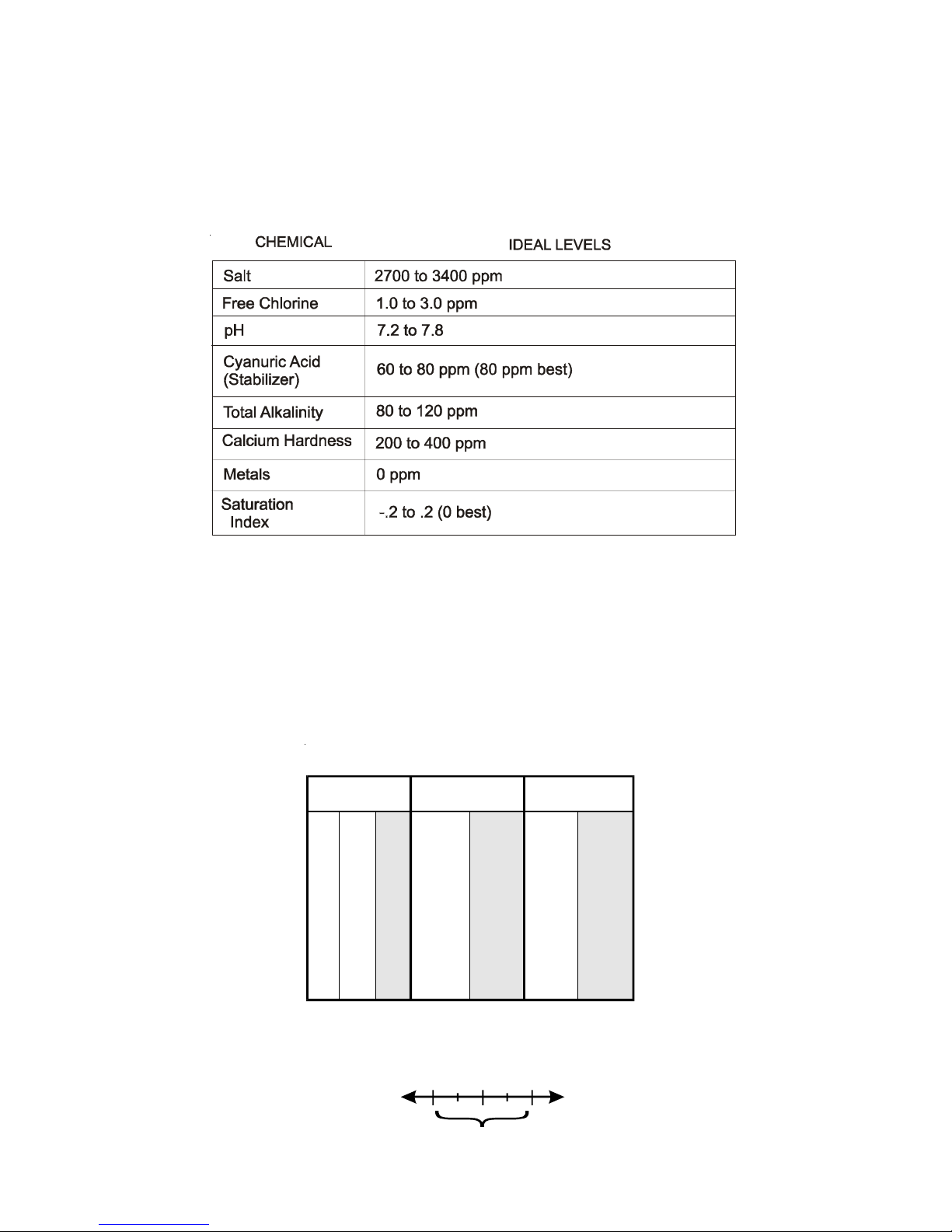
4. Problems resulting from failure to maintain pool water chemistry in accordance with the
recommendations in the owners manual(s).
5. Problems resulting from tampering, accident, abuse, negligence, unauthorized repairs or
alternations, fire, flood, lightning, freezing, external water, degradation of natural stone used in
or immediately adjacent to a pool or spa, war or acts of God.
DISCLAIMER. THE EXPRESS LIMITED WARRANTIES ABOVE CONSTITUTE THE
ENTIRE WARRANTIES WITH RESPECT TO THE ABOVE-IDENTIFIED HAYWARD/
GOLDLINE POOLAUTOMATION AND CHLORINATION PRODUCTS AND IS IN
LIEU OFALL OTHER WARRANTIES, EXPRESS OR IMPLIED, INCLUDING WAR-
RANTIES OF MERCHANTABILITY OR FITNESS FOR A PARTICULAR PURPOSE.
THESE WARRANTIES GIVE YOU SPECIFIC LEGAL RIGHTS, AND YOU MAYALSO
HAVE OTHER RIGHTS OF EQUIPMENT, LOST PROFITS OR REVENUE, COSTS
OF RENTING REPLACEMENTS,AND OTHERADDITIONAL EXPENSES, EVEN IF
THE SELLER HAD BEEN ADVISED OF THE POSSIBILITY OF SUCH DAMAGES.
SOME STATES DO NOT ALLOW THE EXCLUSION OF LIMITATION OF INCI-
DENTAL OR CONSEQUENTIAL DAMAGES, SO THE ABOVE LIMITATION OR
EXCLUSION MAY NOT APPLY TO YOU.
NO WHOLESALER, AGENT, DEALER, CONTRACTOR OR OTHER PERSON IS
AUTHORIZED TO PROVIDE, SUPPLEMENT OR MODIFYANY WARRANTY ON
BEHALF OF HAYWARD/GOLDLINE.
THESE WARRANTIES ARE VOID IF THE PRODUCT HAS BEEN ALTERED IN ANY
WAYAFTER LEAVING THE FACTORY. FOR THE ABOVE-IDENTIFIED CHLORI-
NATION PRODUCTS, THESE WARRANTIES ALSO ARE VOID IF, DURING THE
WARRANTY PERIOD, YOU USE A REPLACEMENT CHLORINATOR CELL OTHER
THANAN UNMODIFIED, NEW HAYWARD/GOLDLINE CHLORINATOR CELLPUR-
CHASED FROM HAYWARD/GOLDLINE. IFAWARRANTY BECOMES VOID, YOU
STILL MAY PURCHASE SERVICE AND/OR TELEPHONE TECHNICAL SUPPORT
AT THE THEN CURRENT TIME AND MATERIAL RATES.