41 42
INTRODUCTION
INDEX
OAudio system with 4 + N wires installation.
OFor installations with several access doors.
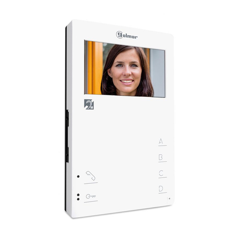
OUp to three telephones in the same apartment.
OUp to 20 push buttons modules EL610.
OElectronic call type with selectable call tone on EL651 sound module.
OAcoustic call acknowledgement signal.
OAcoustic busy channel acknowledgement signal.
OMaximum distance between transformer and door panel: 300m. / 2,5mm section.
OMaximum distance between lock release and door panel: 300m. / 2,5mm section.
OMaximum distance between door panel and last telephone: 300m.
OJust 1 TF-104 transformer (12Va.c., 1.5A) will be required for each door panel.
ODoor opening timed at 3 seconds.
OA.c lock release operated by relay.
.
.
.
.
2
2
SYSTEM CHARACTERISTICS
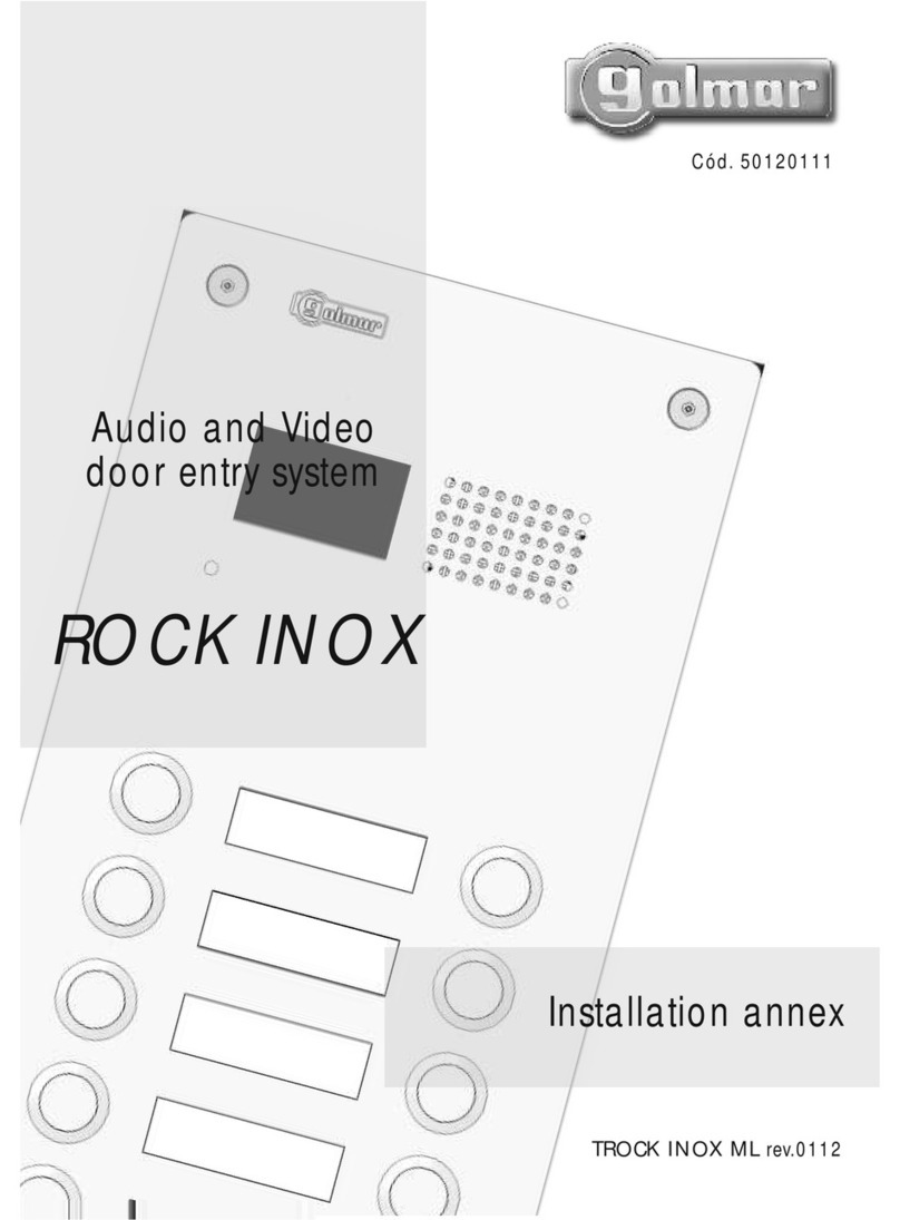
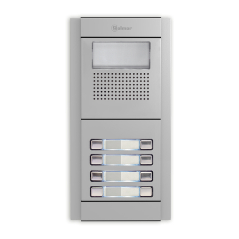
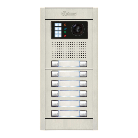
oor panel description.
D
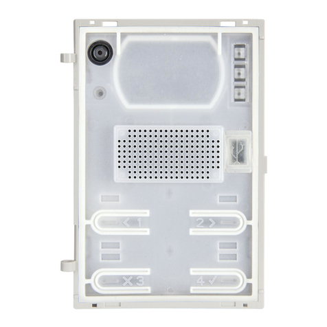
General detail of parts, for assembly the door panel. Aluminium modules
Electronic
modules
Frame modulesEmbedding boxes
SAFETY PRECAUTIONS
OInstallormodifytheequipmentwithoutthepowerconnected.
OTheinstallationandhandlingoftheseequipmentsmustbeperformedbyauthorisedpersonnel.
OTheentireinstallationmustbeatleast40cm.awayfromanyotherinstallation.
OWithpowersupply:
wDonotuseexcessiveforcewhentighteningtheconnectorscrews.
wInstallthepowersupplyinadryandprotectedplacewithoutriskofdriporwaterprojections.
wAvoidtoplaceitneartoheatingsources,industylocationsorsmokyenviroments.
wDonotblockventilationholesoftheunitsothataircancirculatefreely.
wToavoiddamage,thepowersupplyhastobefirmlyfixed.
wTo avoid an electrical shock, neither remove the protection cover nor handle the connected wire in
theterminals.
Checktheproperspecifiedinputvoltageto"PRI"terminalsofthetransformer.
Withtelephones:
wDonotuseexcessiveforcewhentighteningtheconnectorscrews.
wInstallthetelephonesinadryandprotectedplacewithoutriskofdriporwaterprojections.
wAvoidtoplaceitneartoheatingsources,industylocationsorsmokyenviroments.
wDonotblockventilationholesoftheequipmentssothataircancirculatefreely.
Beforetoconnectthesystem,checktheconnectionsbetweendoorpanel,telephonesandtransformer
connection.
Doalwaysfollowtheenclosedinformation.
w
O
O
O
DOOR PANEL DESCRIPTION
O
O
O
O
Tomakeacallthevisitorshould press thepushbuttoncorrespondingtotheapartmenthe wishes to
contact. An acoustic tone will be heard confirming the call as the push button is pressed. At this
momentthecallwillbereceivedatthetelephoneinthedwelling.
Withseveral accessdoors, theother(s) door panel(s)will be automatically disconnected: ifa visitor
tries to call from other panel an acoustic tone will be heard confirming the system is busy. If the
callisnotansweredin30seconds,thesystemwillbefreed.
Toestablishcommunicationpickupthetelephonehandset.Thecommunicationwilllastfor3minutes
oruntilthehandsetisreplaced.Oncethecommunicationhasfinishedthesystemwillbefreed.
To open the door, press the door release push button at any moment during call and
communicationprogresses:withonepress,thedoorreleaseoperatesduring3seconds.
SYSTEM OPERATION
Introduction...........................................41
Index.....................................................41
Safetyprecautions...................................41
Systemcharacteristics..............................42
Systemoperation....................................42
Doorpaneldescription.......................42-43
Modulesdescription....................................
SoundmoduleEL651 ...........................44
PushbuttonsmoduleEL610A.................45
Doorpanelinstallation................................
Embeddingboxpositioning ...................46
Embeddingboxinstallation ..............46-47
Assemblyelectronicmodules .................47
Holdtheframe.....................................48
Pushbuttonswiring...............................48
Shortconnectioncable..........................49
ConnectioncableRAP-610A..................49
Calltoneselection................................49
Finaladjustments .................................50
Placethenameplatelabels ....................50
Closetheframe....................................50
Doorpanelassembly ............................51
Closethedoorpanel.............................51
Powersupplyinstallation..........................52
Lockreleaseinstallation...........................52
Telephoneinstallation..................................
T-900,T902,T900VD,T910yT910R.....53
T700,T712VDyT710R ........................54
Installationsdiagrams .................................
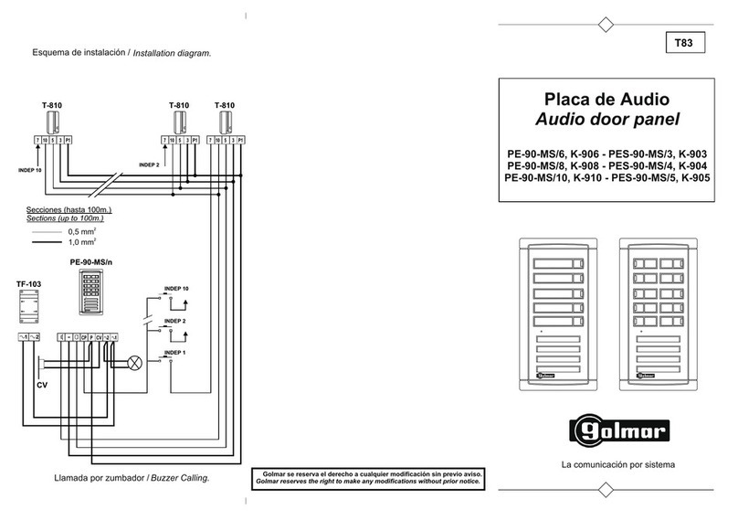
Severalaccessdoors........................55-56
Replacement..............................................
ConversiontableSerie60/Serie90.........57
Optionalconnections..............................58
Troubleshootinghints ..............................58
Compliance...........................................59
Firstof allwe would like to thankand congratulateyou for thepurchase ofthis product manufactured by
Golmar.
The commitment to reach the satisfaction of our customers is stated through the ISO-9001 certification
andforthemanufacturingofproductslikethisone.
Its advanced technology and exacting quality control will do that customers and users enjoy with the
legion of features this system offers. To obtain the maximum profit of these features and a properly wired
installation,wekindlyrecommendyoutoexpendafewminutesofyourtimetoreadthismanual.
