manuals.online logo
Brands
  1. Home
  2. •
  3. Brands
  4. •
  5. golmar
  6. •
  7. Intercom System
  8. •
  9. golmar Stadio Plus T4000ML User manual

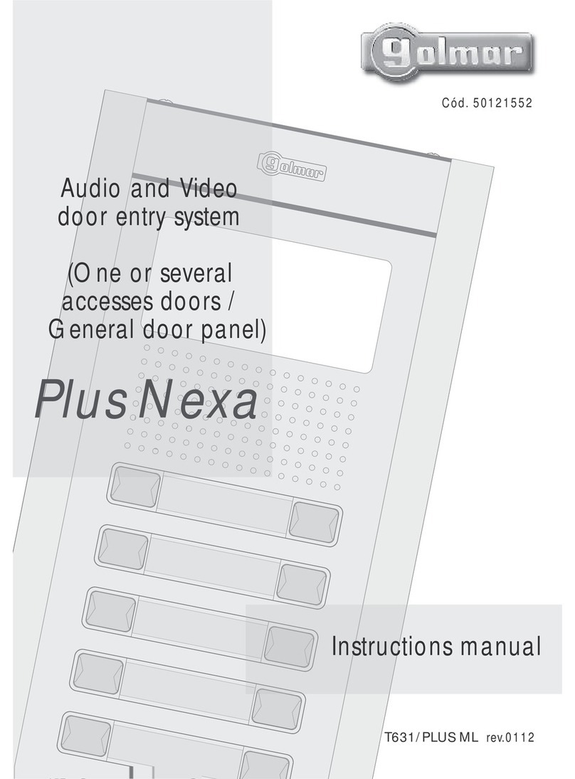
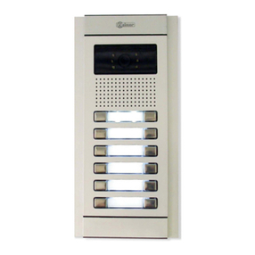
golmar Stadio Plus T4000ML User manual

Stadio Plus
T4000ML
rev.0104
Audio
door entry system
Kits
4+'n' wires installation
Instructions manual
Golmar se réserve le droit de toute modification sans préavis.
First of all we would like to thank and congratulate you for the purchase of this
product manufactured by Golmar.
The commitment to reach the satisfaction of our customers is stated through the ISO-
9001 certification and for the manufacturing of products like this one.
Its advanced technology and exacting quality control will do that customers and
users enjoy with the legion of features this system offers. To obtain the maximum profit of
these features and a properly wired installation, we kindly recommend you to expend a few
minutes of your time to read this manual.
O
O
To make a call the visitor should press the push button corresponding to the
apartment he wishes to contact. An acoustic tone will be heard confirming the
call as the push button is pressed. At this moment the call will be received at the
telephone in the dwelling.
To establish communication pick up the telephone handset.
O
O
O
Do not use excessive force when tightening the transformer connector screws.
Install the equipment without the power connected. Disconnect from power before
any system modification. Check that the input voltage is lower than 230Va.c.
Before to connect the system, check the connections between door panel and
telephones, and the transformer connection. Do always follow the enclosed
O
O
O
O
Audio system with 4 + N wires installation.
Just 1 TF-104 transformer (12Va.c., 1.5A).
Electronic call with acoustic acknowledgement signal.
a.c. lock releases activation.
OUp to three telephones in the same apartment.
1
INTRODUCTION
SYSTEM CHARACTERISTICS
SYSTEM OPERATION
STARTING RECOMMENDATIONS
DOOR PANEL INSTALLATION
2
1650
1850
1450
The upper part of the door panel should be placed at 1,65m. height roughly. The hole dimensions
will depend on the kit to be installed.
1 or 2 push buttons kits: 125(W) x 140(H) x 56(D) mm.
3 to 10 push buttons kits: 125(W) x 220(H) x 56(D) mm.
The door panel has been designed to be placed under most of the environmental conditions.
However it's recommended to take additional cautions like rainproof covers.
DIN 46277
f3,5 x 25
DIN-7971
f3,5 x 25
DIN-7971
nstalling the TF-104
Itransformer.
To install the transformer directly on the wall,
insert the fixing flanges.
Drill two holes of Ø6mm. and
insert the wallplugs.
Fix the transformer with the specified
screws.
The transformer can be installed on a DIN guide (3 units) simply pressing it.
To disassemble the transformer from the DIN guide, use a plain screwdriver to lever
the flange as shown on the picture.
The transformer must be installed in a dry and
protected place. It's recommended to protect
the transformer by using a thermo-magnetic
circuit breaker.
POWER SUPPLY INSTALLATION
mbedding box
Epositioning.
DOOR PANEL INSTALLATION 3DOOR PANEL INSTALLATION
4
lace the nameplate labels.
P
Break the bottom flange
to pass the cables through.
reparing the
Pembedding box.
Pass the wiring through the hole made in
the bottom part of the embedding box.
Level and flush the embedding box.
Once the embedding box is placed,
remove the protective labels
from the attaching door panel holes.
old the door panel on the
Hembedding box.
Select a direction to open the door panel; this selection should ease
the door panel wiring.
The opening direction will be settled through the hinges position,
that must be passed through the header clips as shown.
For example, if the hinges are placed on both clips of the lower
header, the door panel will open downwards; if they are placed
on the right clips of both headers, the door panel will open to left.
To hold the door panel on the embedding box,
insert the hinges in the embedding box lockers
as shown.
Open the label holder.
Place the label and
close.
inal
Fadjustments.
If after starting the system it's considered that the audio
volume isn't correct, proceed with the necessary
adjustments as shown.
Once the nameplate labels are placed, wire the
lamps from different modules and connect them
to terminals L1 and L2 of the sound module,
as it's shown on the installation diagrams.
lose the door
Cpanel.
Fix the door panel by using the supplied
screws.
Finish the door panel assembly by pressing
the closing heads.
5INSTALLATION DIAGRAM
6
escription of the T-900
Dtelephone.
a.
b.
c.
d.
e.
f.
g.
a
d
c
e
e
g
f
b
TELEPHONE INSTALLATION
Telephone handset.
Speaker grille.
Microphone hole.
Subjection hole.
Telephone cord connectors.
Door release push button.
Hook switch.
To open the telephone insert
a plain screwdriver into the slots and
rotate it as shown.
Avoid to place the telephone near to heating sources,
in dusty locations or smoky environments.
The telephone can be fixed using an electrical embedding
box or directly on the wall, as shown on the picture.
If the telephone will be installed directly over the wall,
drill two holes of Ø6mm. on the specified positions,
using 6mm. wallplugs and Ø3,5 x 25mm. screws.
Pass the installation wires through
the corresponding hole and
connect them as shown on the
installation diagrams.
Close the telephone as shown on the picture.
Once the telephone is closed, connect the handset
using the telephone cord and put it on the craddle.
CVCPL1 L2
ind. 1
ind. 1
ind. 2
ind. 2
ind. 3
P
CN1
-
~1~2
TF-104
Stadio Plus
SEC
~~
PRI
~~
0
0
10
10
5
5
3
3
P1
P1
Main
SECTIONS CHART
ne access door.
O
ections chart.
S
0, ind, 5, , 10, , P, P1 0,25mm² 0,50mm²
0,50mm² 1,00mm²
1,00mm² 2,50mm²
Terminal 100m.
Maximum distance
300m.
–, 3
~1, ~2, CV
For longer distances than the specified contact with your distributor.

Other golmar Intercom System manuals

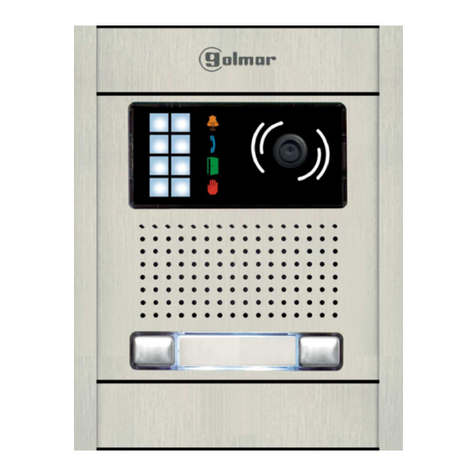
golmar V2PLUS User manual

golmar

golmar V2PLUS User manual

golmar SV-372S Colour User manual

golmar

golmar SV-372S Colour User manual

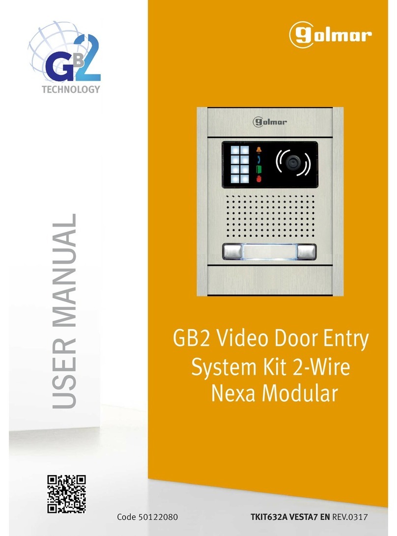
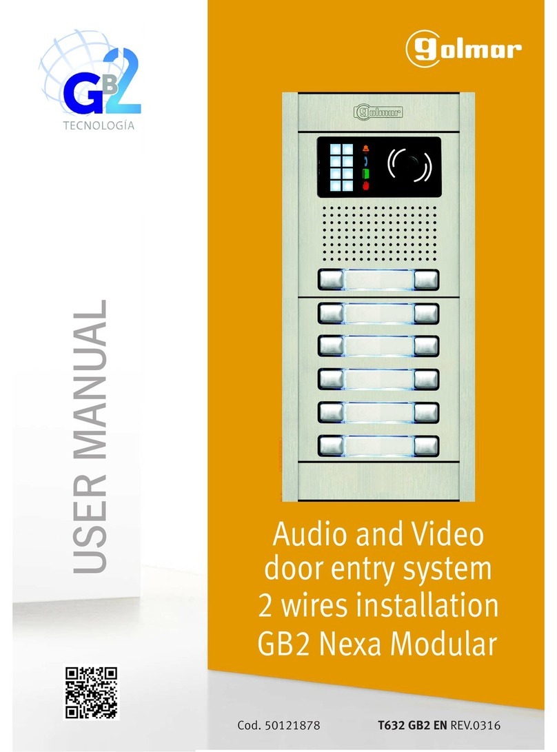
golmar GB2 Nexa Modular User manual

golmar

golmar GB2 Nexa Modular User manual

golmar S5110/ART 7W User manual

golmar

golmar S5110/ART 7W User manual

golmar T-590VD User manual

golmar

golmar T-590VD User manual

golmar KIT SOUL S4110 ART 1 G2+/T-ART G2+ User manual

golmar

golmar KIT SOUL S4110 ART 1 G2+/T-ART G2+ User manual

golmar EL620/2Plus User manual

golmar

golmar EL620/2Plus User manual

golmar KIT SOUL S4110 ART 1 User manual

golmar

golmar KIT SOUL S4110 ART 1 User manual

golmar T555ML User manual

golmar

golmar T555ML User manual

golmar GB2 Nexa Modular User manual

golmar

golmar GB2 Nexa Modular User manual

golmar PCM/G+ User guide

golmar

golmar PCM/G+ User guide

golmar m700 User manual

golmar

golmar m700 User manual

golmar Gtwin Series User guide

golmar

golmar Gtwin Series User guide

golmar Nexa 90 User manual

golmar

golmar Nexa 90 User manual

golmar G2+ Art 4 User manual

golmar

golmar G2+ Art 4 User manual

golmar Jazz GB2 User manual

golmar

golmar Jazz GB2 User manual

golmar TEKNA HF TWIN User manual

golmar

golmar TEKNA HF TWIN User manual

golmar 4130/AL User manual

golmar

golmar 4130/AL User manual

golmar T4ML User manual

golmar

golmar T4ML User manual

golmar Jazz GB2 User manual

golmar

golmar Jazz GB2 User manual

golmar SV805AL User manual

golmar

golmar SV805AL User manual

golmar ART 7T/G2+ MONITOR User manual

golmar

golmar ART 7T/G2+ MONITOR User manual

golmar 50124319 User manual

golmar

golmar 50124319 User manual

golmar SOUL S5110 User manual

golmar

golmar SOUL S5110 User manual

Popular Intercom System manuals by other brands

Safe S31IP instruction manual

Safe

Safe S31IP instruction manual

Bpt XM/200 installation instructions

Bpt

Bpt XM/200 installation instructions

AES global Styluscom Video manual

AES global

AES global Styluscom Video manual

AES MultiCOM Lite 4G manual

AES

AES MultiCOM Lite 4G manual

Toa EXES-1000 Installation handbook

Toa

Toa EXES-1000 Installation handbook

Altair WBP-202 owner's manual

Altair

Altair WBP-202 owner's manual

Auta NEOS DIGITAL 751925 manual

Auta

Auta NEOS DIGITAL 751925 manual

PACH & COMPANY AeGIS 4000 Installation and programming manual

PACH & COMPANY

PACH & COMPANY AeGIS 4000 Installation and programming manual

Midland BT City Instruction guide

Midland

Midland BT City Instruction guide

Aiphone JP-DVF-PR installation guide

Aiphone

Aiphone JP-DVF-PR installation guide

Alarmtec 4.3" Video Door Phone user manual

Alarmtec

Alarmtec 4.3" Video Door Phone user manual

Swann Advanced Quad Processor quick start guide

Swann

Swann Advanced Quad Processor quick start guide

urmet domus Miwi Matibus SE manual

urmet domus

urmet domus Miwi Matibus SE manual

Alcad 967 Series manual

Alcad

Alcad 967 Series manual

GVS S Series user manual

GVS

GVS S Series user manual

Akuvox E18C Administrator's guide

Akuvox

Akuvox E18C Administrator's guide

Fermax DUOX SKYLINE Series Installer manual

Fermax

Fermax DUOX SKYLINE Series Installer manual

SKYTRONIC 350.009 instruction manual

SKYTRONIC

SKYTRONIC 350.009 instruction manual

manuals.online logo
manuals.online logoBrands
  • About & Mission
  • Contact us
  • Privacy Policy
  • Terms and Conditions

Copyright 2025 Manuals.Online. All Rights Reserved.