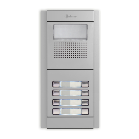
golmar T631/PLUS User manual

P
lus Nexa
Cód. 50121552
Instructions manua
l
Audio and Video
door entry system
(One or several
accesses doors /
General door panel)
T631/PLUS ML rev.0112

105
INTRODUCTION
STARTING RECOMMENDATIONS
INDEX
Firstofallwe would like to thank and congratulate you for the purchase of this product manufactured by
Golmar.
The commitment to reach the satisfaction of our customers is stated through the ISO-9001 certification
andforthemanufacturingofproductslikethisone.
Its advanced technology and exacting quality control will do that customers and users enjoy with the
legion of features this system offers. To obtain the maximum profit of these featuresand a properly wired
installation,wekindlyrecommendyoutoexpendafewminutesofyourtimetoreadthismanual.
O
O
O
O
O
Donotuseexcessiveforcewhentighteningthepowersupplyconnectorscrews.
Theentireinstallationmustbeatleast40cm.awayfromanyotherinstallation.
Beforetoconnectthe system, check theconnectionsbetweendoorpanel, monitors, telephones, and
thetransformerconnection.Doalwaysfollowtheenclosedinformation.
Eachtimethepowersupplyisrestarted,orafteramodification,thesystemwillremainblockedduring
30seconds.
Always use RG-59 B/U MIL C-17 or RG-11 coaxial cables, (see page 138). Never use coaxial
antennacable.Ininstallationsnolongersthan100m.,Golmar RAP-5130cablecanbeused.
Introduction.........................................105
Index...................................................105
Startingrecommendations.....................105
Safetyprecautions.................................106
Systemcharacteristics.....................106-107
Systemoperation..................................107
Doorpaneldescription..........................108
Modulesdescription....................................
SoundmoduleEL631Plus/EL640Plus...109
PushbuttonsmoduleEL610D...............110
Doorpanel ................................................
.................111
Embeddingboxinstallation ..........111-112
Assemblyelectronicmodules ...............112
HoldtheFrame ..................................113
Pushbuttonsconnection...............113-114
Pushbuttonscoding............................114
Soundmoduleconfiguration ........115-116
Programming(generalpanel) .......117-119
FunctionconnectorCn5description......119
Finaladjustments ...............................120
Placethenameplatelabels ..................120
Doorpanelassembly ..........................121
Closethedoorpanel...........................121
Powersupplyinstallation........................122
Lockreleaseinstallation.........................122
PlateaPlus/TeknaPlusmonitor ....................
Description........................................123
Embeddingboxpositioning
Functionpushbuttons.........................124
El562module....................................125
Endoflineresistor...............................125
Frontfilmreplacement ........................125
Monitorconnectordescription .............126
Monitorinstallation.............................127
Programming.....................................128
T-940Plustelephone...................................
Description........................................129
Functionpushbuttons.........................129
Telephoneinstallation.........................130
Programming.....................................131
T-740Plustelephone...................................
Description.................................132-133
Functionpushbuttons.........................133
Telephoneinstallation.........................134
Programming.....................................135
Installationdiagrams...................................
Connectionofana.c.lockrelease........136
Linkofseveralpowersupplies...............136
Videoinstallationwithcoaxial.......137-138
Videoinstallationwithoutcoaxial...139-140
Audioinstallation........................141-142
Videoinstalltion(generalpanel)....143-146
Audioinstallation(generalpanel)..147-148
Optionalconnections ....................149-153
Troubleshootinghints ............................154
Compliance.........................................155
106 SAFETY PRECAUTIONS
SYSTEM CHARACTERISTICS
OAudioandvideodoorentrysystemwithsimplifiedinstallation:
wAudiodoorentrysystemwith4commonwiresinstallation.
wVideodoorentrysystemwith3commonwirespluscoaxialcableinstallation.
wVideodoorentrysystemwith4commonwiresplustwistedpairinstallation.
OSoundmodulewithtwooperatingmodes(EL500orEL501).
OUnlimitednumberofdoorpanels(access)beingnotnecessarytheuseofswitchingunits.
OUpto120monitors/telephonesperinstallationorbackbone.
OGeneraldoorpanel(EL501mode):Upto120monitors/telephones,distributedinmax.120buildings.
OEL560moduleforvideoinstallationswithtwistedpaircable,integratedinsoundmodule.
OCommunicationsresistorforthesystemUNOorPLUS,integratedinsoundmodule.
OAcousticbusychannelandcallacknowledgementsignals.
ODooropeningtimedat3seconds.
OInputforexternaldoorreleasepushbutton(timedat3or15seconds).
Oa.cord.clockreleaseoperatedbyrelay.
OUptothreemonitorsortelephonesinthesameapartmentwithoutadditionalpowersupplies.
OWithT-940Plustelephones:
wPrivacyonaudiocommunications.
wThree-positioncontrolforcallvolume:maximum,mediumandminimum.
wIntercommunicationfunctionwithothermonitorortelephoneofthesameapartment.
wInputforexternaldoorbellpushbutton.
wOutputforadditionalcallrepeater.
wCalltoamasterporter'sexchange.
wPaniccalltotheporter'sexchange.
wDifferent call reception tones depending where the call is comming from: main or slave door
panels,doorbellpushbutton,intercom,...
OWithT-740Plustelephones,additiontotheabovefeatures:
wThree-positioncontrolforcallvolume:maximum,mediumandoff.
wInputforexternaldoorreleasepushbutton. Continue
O
O
O
O
w
w
w
w
w
O
w
w
w
O
O
Installormodifytheequipmentwithoutthepowerconnected.
Theinstallationandhandlingoftheseequipmentsmustbeperformedbyauthorisedpersonnel.
Theentireinstallationmustbeatleast40cm.awayfromanyotherinstallation.
Withpowersupply:
wDonotuseexcessiveforcewhentighteningtheconnectorscrews.
Installthepowersupplyinadryandprotectedplacewithoutriskofdriporwaterprojections.
Avoidtoplaceitneartoheatingsources,industylocationsorsmokyenviroments.
Donotblockventilationholesoftheunitsothataircancirculatefreely.
Toavoiddamage,thepowersupplyhastobefirmlyfixed.
Toavoid anelectricalshock,neither remove the protectioncovernorhandlethe connected wirein
theterminals.
Withmonitor,telephonesanddistributor:
Donotuseexcessiveforcewhentighteningtheconnectorscrews.
Installtheequipmentsinadryandprotectedplacewithoutriskofdriporwaterprojections.
Avoidtoplaceitneartoheatingsources,industylocationsorsmokyenviroments.
wDonotblockventilationholesoftheequipmentssothataircancirculatefreely.
Remember, the installation and handling of these equipments must be performed by authorized
personnelandintheabsenceofelectricalcurrent.
Doalwaysfollowtheenclosedinformation.

107
SYSTEM OPERATION
OTo make a call the visitor should press the push button corresponding to the apartment he wishes to
contact. An acoustic tone will be heard confirming the call is in progress once the push button has
been pressed. At this moment the call will be received at the monitor (telephone) in the dwelling.
During the call the visitor can correct his call by pressing a push button corresponding to a different
apartment,inwhichcasetheoriginalcalliscancelled.
OInsystemswithseveralaccessesdoors,theother(s)doorpanel(s)willbeautomaticallydisconnected:
If a visitor tries to call from other door panel an acoustic tone will be heard confirming the system is
busyandtheledofbusysystemfrominformativewindowwilllights(Ifitexists).
OGeneral door panel (EL501 mode): If the call is made from the general door panel, the inner door
panel of the building called and other possible general door panel will remain automatically
disconnected, if another visitor tries to call from an inner busy door panel or from another general
door panel, an acoustic tone will be heard confirming the system is busy and the led of system busy
willblink(inthegeneraldoor panel). The door panels of the othersinnerbuildingswillremainfreeto
beused.
OGeneraldoorpanel(EL501mode):Inthecasethatthecallismadefromaninnerdoorpanel,therest
of inner door panels will remain free to be used. From general door panels only will be able to make
callsto theinnerbuildings whosedoorpanelsarenotinuse,if thevisitortries tomakeacallto abusy
inner door panel, an acoustic tone will be heard confirming the system is busy and the led of system
busyfrominformativewindowwillblink.
OThe call tone will be reproduced on the monitor during 3 seconds: after this time the picture will
appear on the master monitor without the visitor being aware of this. To see the picture in a slave
monitor press the push button, dissapearing the picture on the other monitor. If the call is not
answeredin45seconds,thesystemwillbefreed.
OToestablishcommunicationpickupthemonitor(telephone)handset.
OThe communication will last for one and a half minutes or until the handset is replaced. Once the
communicationhasfinishedthesystemwillbefreed.
OTo open the door, press the door release push button during call or communication progresses: with
onepress,thedoorreleaseoperatesduring3seconds.Duringthelockreleaseactivationanacoustic
tonewillbeheardonthedoorpanelconfirmingthelockreleaseisactivated.
OThemonitorandtelephonespushbuttonsdescriptionisshownonpages124,129&133respectively.
SYSTEM CHARACTERISTICS
wAllowsoneofthesefunctionsatonce,Configurationwithdipswitch Sw1(seepage133):
w"Autoswitch-on"function.
wOutputforauxiliaryrelayactivation(18Vdc/0,5Amaximum).
wCalltoaslaveporter'sexchange.
wIntercommunicationfunctionwithothermonitorortelephoneofthesameapartment.
OWithPlateaPlus/TeknaPlusmonitors,additiontotheT-940Plustelephonesfeatures:
w"Autoswitch-on"function.
w"Video-spy"functionwiththecommunicationchannelremainingfree.
wCalltoaslaveporter'sexchange.
wActivationoftwoauxiliarydevices:secondarytelecamera,courtesylight,...
wB/W&Colormonitor.
wBrightnessandcontrastcontrol(colorcontrolincaseofcolorscreen).
Coming from previous page

108 DOOR PANEL DESCRIPTION
Sound module
EL631 Plus
EL640 Plus
oor panel description.
D
Push buttons electronic module
EL610D
Short connection cable, It is supplied with EL610D module (16 cm length).
, for 5 single push-buttons or 10 double push buttons.
, on video systems with color camera.
, on audio systems.
Connection cable RAP-610D (27 cm length).
General detail of parts, for assembly the door panel.
Aluminium modules
Electronic
modules
Frame modulesEmbedding boxes
Push buttons module
Main module
Door panel description.
For the connection of the push-buttons between the sound module and the push
buttonsmoduleEL610Dandbetweenpush-buttonsmodulesEL610D.
For the connection of the push-buttons between the sound module and the push
buttonsmoduleEL610Dandbetweenpush-buttonsmodulesEL610D.
This cable is necessary when the distance between modules to connecting is
greaterduetothedistributionofthesemodulesinthedoorpanel/s.

109
ound module description.
s
Microphone.
Speaker.
Door panel audio adjustment.
Monitor audio adjustment.
Front side.
Sound module push buttons (x2).
Installation terminals CN2 (Plus Nexa Bus).
Label.
Push buttons connector CN9.
Back side.
:
: "N.O" contact free for lock release.
: Positive, ground.
: Digital communication.
: Audio output communication.
: Audio input communication.
: Twisted pair video signal input.
: Twisted pair video signal output.
: Coaxial shield.
: Video signal coaxial input.
: Video signal coaxial output.
"C" contact free for lock release.
Configuration dip switch SW1.
Push button number.
Color camera (only EL631 Plus sound module).
CV1
CV2
+,
D
Aout
Ain
Vi+,Vi-
Vo+,Vo-
Malla
Vi+
Vo+
_
Installation terminals:
Note: See installation diagrams for wiring.
MODULES DESCRIPTION
CV2CV1 __
++Ai Vi
-
Vi + VO
-
VO+
DAo
Malla
Configuration dip switch SW2.
Function connector Cn5.

110
ush buttons electronic module EL610D description.
P
Front side.
Push buttons module (x10).
Configuration dip switch
(Push buttons call code).
Push button number.
Input/Output push buttons connector (x3).
Back side.
MODULES DESCRIPTION

90CS
CEA90C
99
143
40
Door panel
Model
An
Al
P
90C
CEV90C
99
250
56
90
CEV90
99 mm.
328 mm.
56 mm.
1650
1850
1450
111
DOOR PANEL INSTALLATION
mbedding box positioning.
E
The upper part of the door panel should be placed at 1,65m. height roughly. The hole dimensions
willdependonthetypeofdoorpanel.
The door panel has been designed to be placed under most of the environmental conditions.
However it's recommended to take additional cautions like rainproof covers. To obtain a good
qualitypictureonvideodoorentrysystems,avoiddirectincidencefromlightsources.
reparing the cables entry.
P
Break the bottom flange to pass the cables through. In case of door panels
with more than one embedding box, break the side flanges and
attach the embedding boxes using UC junctions.

ssembly the electronic modules.
A
Insert the sound module in the top part of the module frame.
Align the tabs on the sound module in their respective housings of the module frame and
later exercise a light pressure until correct placement.
Sound module
EL631 Plus
EL640 Plus
Push buttons electronic
module EL610D
Frame
If there is push buttons module repeat the above process, locating under the sound module,
as shown in the drawing.
Frame
112 DOOR PANEL INSTALLATION
lace the embedding box.
P
Passthewiringthroughtheholemadeinthebottompartofthe
embedding box. Level and flush the embedding box. Once
the embedding box is placed, remove the protective labels
fromtheattachingdoorpanelholes.

113
DOOR PANEL INSTALLATION
old the frame on the embedding box.
H
lug the push buttons with the short
Pconnection cable.
Between push buttons modules EL610D of the same embedding box,
insert the short connection cable of the low connector of the first push
buttons module to the top connector of the second push buttons
module,asshowninthedrawing.
Insert the short connection cable that it is supplied with the product
EL610D, in the push buttons connector of the sound module and the
other end of the connection cable in the connector placed in the top
partofthepushbuttonsEL610Dmodule,asshowninthedrawing.
BetweenpushbuttonsmodulesEL610Dof differentembeddingtboxes,
insert the short connection cable in the low connector of the last
module EL610D of the first embedding box and the other end of the
connection cable in the middle connector of the last push buttons
moduleEL610Dplacedinthelowpartofthe secondembeddingbox,
asshowninthedrawing.
Insert the hinge that it is supplied with the product in the embedding
box,asshowninthedrawing.
Toholdthe frameontheembedding box,insertthe hingeinthe
housings arranged for this purpose in the frame, as shown in
thedrawing.
The frame can now be folded horizontally facilitating the connection
and adjustments in the sound module and push buttons electronic
module.

114 DOOR PANEL INSTALLATION
lug the push buttons with the connection
Pcable RAP-610D.
onfiguration of the push-buttons code.
C
Push buttons module EL-610D
2
Dip1
1
4
6
8
3
5
7
71
Dip2
Dip3
Dip4
Dip5
Dip6
Dip7
Dip8
Push buttons code
Module configuration option
P1 P2 P3 P4 P5 P6 P7
1
21
41
61
11
31
51
2
22
42
62
12
32
52
72
3
23
43
63
13
33
53
73
4
24
44
64
14
34
54
74
5
25
45
65
15
35
55
75
6
26
46
66
16
36
56
76
7
27
47
67
17
37
57
77
8
28
48
68
18
38
58
78
9
29
49
69
19
39
59
79
10
30
50
70
20
40
60
80
P8 P9 P10
10
12
9
11
13
81
101
122
91
112
82
102
123
92
113
83
103
124
93
114
84
104
125
94
115
85
105
126
95
116
86
107
127
96
117
87
108
128
97
118
88
109
129
98
119
89
110
130
99
120
90
111
131
100
121
Dip switch
On
On
Off
Off
Off
Off
Off
Off
Off
Off
Off
Off
On
Off
Off
Off
Off
On
Off
Off
Off
Off
Off
Off
Off
Off
Off
Off
Off
On
Off
Off
Off
Off
On
Off
Off
Off
Off
Off
Off
Off
Off
Off
Off
Off
On
Off
Off
Off
Off
On
Off
Off
Off
Off
On
On
On
On
On
On
On
Off
Off
Off
Off
Off
On
Off
Off
Off
Off
Off
Off
Off
On
Off
Off
On
Off
Off
Off
Off
Off
Off
Off
On
Off
Off
On
Off
Off
Off
Off
Off
Off
Off
Off
Off
Off
Off
Off
Off
Important: Select a different configuration option for each module EL610D.
P1- P10: Push button 1 to push button 10.
*
( )
*
( )Note:Sound module,factory set the code "106" in P1 and "132" in P2.
Use the connection cable RAP-610D, for the connection of the push buttons
between the sound module and the push buttons module EL610D and
between push buttons modules EL610D, when the distance between
modulestoconnectingisgreaterduetothecompositionofthedoorpanels.
The push buttons module EL610D must be configured, to assign a call code to
thepushbuttons(usethetool thatissuppliedwiththesoundmodule).Make
thisconfigurationwiththedipswitchplacedinthebacksideofthemodule.
Depending on the setting selected, the push buttons are assigned to a specific
callcode.
In case to combine these door panels with coded door panels or porter's
exchange, it will be necessary to known the call code of each push button, as
showninthetablebelow.

115
escription of the SW1 configuration dip-switch of
Dthe sound module.
Placed to OFF if the EL631/Plus module is configured as EL500
.
Set to ON if the EL631/Plus module is configured as EL501
(generaldoorpanel).
operating
mode operating mode
Selects the d done from the ('AP'
terminal),seepage149.
PlacedtoON:dooropeningtimedat3seconds.
SettoOFF:dooropeningtimedat15seconds.
oor opening time, external push button
Selectsthetypeofcabletobeusedforthevideosignal.
PlacedtoOFF:coaxialcableRG-59oRG-11.
SettoON:twistedpair.
Placed to OFF if the door panel has telecamera. In case of door panels
withouttelecamera(EL640Plussoundmodule)settoON.
Plussystem,loadstheinstallation withacommunicationsresistorPlus.Fora
propersystemoperation, placed to ONonlyinthe closest doorpaneltothe
backbone installation or in the general door panel (if exists), set the rest to
OFF.
SettoONsothatthevolumetoneemittedbythedoorpanel:
(callreception,busy systemandlock release)areHIGH,orplaced toOFFif a
LOW volumetoneisdesired.
UnoSystem,
proper system operation, set to ON only in the closest door panel to the
backboneinstallation,placedtheresttoOFF.
WithdigitalrepeaterRDPlus/Uno:
In the backbone installation or after the inner door panel in systems with
generaldoorpanels,placedthedoorpanel/stoOFF.
loadstheinstallationwithacommunicationsresistorUno.Fora
6
6
7
6
7
6
Placed to ON,
porter'sexchange(ifexists).SettoOFF,thecallisreceivedintheapartment.
In general door panels systems with porter's exchange, this function is only
applicabletothegeneraldoorpanelsnottotheinnerdoorpanel/s.
the calls made on the door panel will be transferred to the
Factory default
6
7
8
6
7
8
TheSW1configurationdip-switchislocatedattheupperright
sideofthebackofthemodule.
For dip switch settings, use the tool that is supplied with the
soundmodule.
DOOR PANEL INSTALLATION

116 DOOR PANEL INSTALLATION
inary coding of the SW2 configuration dip switch
Bthe sound module. of
The switches set to OFF have null value. The values of the switches
set to ON are shown in the enclosed chart.
The backbone code will be calculated as the sum result of the
switches values set to ON.
Example: 64+0+16+0+4+2+1=87
Switch number:
ON value: 4
64 5
32 6
16 7
88
49
210
1
escription of the SW2 configuration dip-switch of
Dthe sound module.
Allows to activate the autoswitch-on function (audio-video communication
withoutpreviouscall)atthedoorpanelthathasthisswitchtoONposition.
In systems with several door panels activate this function only in one of
them; in systems with general door panel this function can be activated in
onedoorpanelofeachinnerbackbone(building).
SettoONformonitorortelephonesprogramming.Oncetheprogramming
progress is finished return the switch to OFF position. The programming
processisdescribedonpages128(monitors),131and135(telephones).
In general door panel (EL501 mode), set to ON for general door panel
push buttons programming or backbone (building) monitor/telephones.
The programming process is described on pages 117 to 119. Once the
programmingprogressisfinishedreturntheswitchtoOFFposition.
SettoOFFincaseofamasterdoorpanel.Eachsystemmusthaveonlyone
masterdoorpanel;therestmustbeslaves(ON).
In systems with general door panel, set as master one door panel of each
inner backbone (building) and the general door panel as slave. Of this
way,theuserwillbeabletodistinguishsincedoorpanelarecallinghim.
Switches number 4 to 10 set the building code. In backbones with several
door panels, set the same code in all the panels; in systems with general
door panel, set different codes for each inner backbone (building). Set a
code between 1 and 120 for inner backbones (up to 127 with coded
panel) and a code 0 ( ) for general door panel/s. To set the
codeusebinarycodingasshownonthenextparagraph.
Factory default
Factory default
The SW2 configuration dip-switch is located at the upper left
sideofthebackofthemodule.
For dip switch settings, use the tool that is supplied with the
soundmodule.

117
ConfiguretheEL631/Plus ofthegeneraldoorpanelinEL501mode,(seepage115).module
Locate the SW2 configuration dip switch of the general door
panel to program, placed at the upper left side (back) of the
sound module. With the switches 1 and 3 to OFF, set the
switch 2 to ON: to show that the system is ready for
programming,thegeneraldoorpanelwillreproduceatone.
Pick up the monitor/telephone handset of
the apartment to program and press the
doorrelease pushbuttonuntiltoestablish
communication of audio with the general
doorpanel.
Press the general door panel push button that will call to this
monitor or telephone. At this moment the general door
panel will reproduce a tone. To finish the push button
programmation, replace the monitor/telephone handset;
to show that the push button has been succesfully
programmed,thegeneraldoorpanelwillreproduceatone.
Make a call to check that the push button has been succesfully programmed.
Repeatthesestepstoprogramtherestofpushbuttons.
Once the programming has been finished, set to OFF the programming
switch. If you don't, the general door panel will reproduce a tone to advise
thatthesystemisstillintoprogrammingmode.
eneral door panel (programming modes).
G
Thisprogrammingmodeallowstoassignamonitor/telephone(programmed)tothepushbuttonof
thegeneraldoorpanelthatitwishestocall.
Before the monitors/telephones of the inner door panel/s must be programmed, see page 128
(monitors),131and135(telephones).
IMPORTANT: Before programming the general door panel push buttons, switch off the porter's
exchange(ifexists).
Programming the push button (by call of monitor/telephone):
T-940Plus T-740Plus
Thegeneraldoorpanelpermitsthefollowingprogrammingmodes:
OProgrammingthepushbutton(bycallofmonitor).
OProgrammingthepushbutton(withabackbonecode).
OProgrammingthepushbutton(withamonitor/telephonecode).
OProgrammingthemonitor/telephone.
rogramming the push buttons of the general door panel.
P
GENERAL DOOR PANEL INSTALLATION

118 GENERAL DOOR PANEL INSTALLATION
Define a backbone code to program with dip switches Sw2-4 to Sw2-
10. Set a code between 1 and 120. To set the code use binary
coding,(seepage116).
Pressthegeneraldoorpanelpushbuttonthatiswishedhasthis
backbone code. At this moment the general door panel will
reproduceatone, confirming thatthepush button hasbeen
succesfullyprogrammed.
Repeat these steps to program the rest of push buttons. Once the programming has been finished,
set to OFF the programming switch. If you don't, the general door panel will reproduce a tone to
advisethatthesystemisstillintoprogrammingmode.
Programming the push button (with a monitor/telephone code):
This programming mode allows to assign a monitor/telephonecode to push button of the general
doorpanel.
Locate the SW2 configuration dip switch of the general door
panel to program, placed at the upper left side (back) of the
sound module. With the switches 1 and 3 to ON, set the
switch 2 to ON: to show that the system is ready for
programming,thegeneraldoorpanelwillreproduceatone.
Pressthegeneraldoorpanelpushbuttonthatiswishedhasthis
monitor/telephone code. At this moment the general door
panelwillreproduceatone,confirmingthatthepushbutton
hasbeensuccesfullyprogrammed.
Repeat these steps to program the rest of push buttons. Once the programming has been finished,
set to OFF the programming switch. If you don't, the general door panel will reproduce a tone to
advisethatthesystemisstillintoprogrammingmode.
Define a monitor/telephone code to program with dip switches Sw2-4
to Sw2-10. Set a code between 1 and 120. To set the code use
binarycoding,(seepage116).
Programming the push button ( ):with a backbone code
Thisprogrammingmodeallowstoassignabackbonecodetopushbuttonofthegeneraldoorpanel.
Locate the SW2 configuration dip switch of the general door
panel to program, placed at the upper left side (back) of the
sound module. With the switch 1 to ON and 3 to OFF, set the
switch 2 to ON: to show that the system is ready for
programming,thegeneraldoorpanelwillreproduceatone.

119
GENERAL DOOR PANEL INSTALLATION
DOOR PANEL INSTALLATION
Thisprogrammingmodeallowstoassigntoamonitor/telephoneapushbuttonofthegeneraldoor
panelthatitwishestocall.
Before the push button of the general door panel must be programmed with backbone and
monitor/telephonecode,(seepage118).
Programming the monitor/telephone:
Locate the SW2 configuration dip switch of the general door
panel to program, placed at the upper left side (back) of the
soundmodule.Withtheswitch1 to OFFand3to ON,setthe
switch 2 to ON: to show that the system is ready for
programming,thegeneraldoorpanelwillreproduceatone.
Then program the monitor/telephone, as it is described in the page 128 (monitor), 131 and 135
(telephone), (see manual T1ML if the monitor/telephone is Platea Uno, T-740 Uno or T-940
Uno).
Bearinmindtheconfigurationdipswitch(asitisdescribedinthepreviousstep).
rogramming the monitors and telephones from a general door panel.
P
escription of the function connector CN5.
D
ThefunctionconnectorCn5islocatedattheupperleftsideofthebackof
thesoundmodule.
Plug the cable that is supplied with the module, to realize the following
functions:
10
1
9
2
8
3
7
4
6
5
Top view CN5
Description connector CN5
ð"AP" function: It activates the relay of the lock release "CV1" and "Cv2", configurableactivation
timeof3or15secondsviadipswitchSW1-2(page115),seeconnections(page149).
ð"ICO"function:Forthebusychannelindication,itwillberealizedwithterminals"ICO"and"+12".
ð"Handicap" function: Synthese vocale from FDI (France). The connector includes all wires for
connection(seepage149).
1 Grey (-) Ground.
2 Brown (+12) 12Vdc for activation the lock release.
3 White (ICO) Busy channel indicator.
4 Yellow (AP) External push button to activate the lock release.
5 Violet (+H) For activation of an external illumination.
6 Blue (OP) Handicap.
7 Orange (SC) Handicap.
8 Green (ALM) Handicap.
9 Red (PDB) Handicap.
10 Black (-) Ground.

120 DOOR PANEL INSTALLATION
inal adjustments.
F
If after starting the system it
volume isn
't correct, proceed with the necessary
adjustments as shown
in the drawing
.
The telecamera has a pan and tilt mechanism built in to
adjust the telecamera position.
's considered that the audio
lace the nameplate labels.
P
Open the label holder.
Place the label and
close.
Once finished the works of wiring, configuration and
final adjustments, fix the frame in the embedding
box with the supplied screws.
lose the frame.
C

121
DOOR PANEL INSTALLATION
lose the door panel.
C
oor panel assembly.
D
In assemblies of a single door panel, it is ready from factory
to be mounted.
IMPORTANT:
Tomaketheseadjustments of joiningseveraldoorpanels, see the
document that is supplied with the door panel and follow the
steps that are described in the section" Mechanical assembly
for double door panel" and once finished the adjustments stick
the adhesive gasket (that is supplied with the push buttons
module)intherodofjoiningmodules.
Ifthedoorpanel to installing isofmorethanone module it willbe
necessary make some adjustments to join a door panel with
otherone.
Fixthedoorpanelbyusingthesuppliedscrews.
Finish the door panel assembly by placing the closing
heads,puttheheadononesideandthenmakeaslight
pressureontheotherend,toitscorrectplacement.

122
LOCK RELEASE INSTALLATION
nstalling the FA-PLUS and FA-PLUS/C power supplies.
I
DIN 46277
3,5 x 25
DIN-7971
3,5 x 25
DIN-7971
M 4 x 8
3,5 x 25
DIN-7972
DIN-963
POWER SUPPLY INSTALLATION
ock release installation.
L
Replace the protection cover once the input terminals have been wired.
It'srecommendedtoprotect the power supply by using a
thermo-magnetic circuit breaker. Use a ground
connectionwithFA-Pluspowersupply.
To install the power supply directly on the wall, drill two holes of
Ø6mm. and insert the wallplugs. Fix the transformer with the
specifiedscrews.
The power supply can be installed on a DIN 46277
guidesimplypressingit.
To disassemble the power supply from the DIN guide,
use a plain screwdriver to lever the flange as shown
onthepicture.
TheFA-Plus/Cmodeluses6unitsoverDINguideand
10unitstheFA-Plusmodel.
IMPORTANT: the maximum number of units that can be connected to a FA-Plus/C power supply is
10, and 50 units in case of a FA-Plus model. Link power supplies to connect more
unitsthanthespecifiedasit'sshownonpage136.
If the lock release will be installed in a metal door, use a Ø3,5mm.
drillandtapthehole.Incaseofwooddoor,useaØ3mm.drill.
IMPORTANT:thelockreleasemustbeof12Vd.c.ora.c.
Seepage136(a.c.lockreleases)andpage137to148(d.clockreleases)
Installthepowersupplyinadryandprotectedplacewithoutriskofdriporwaterprojections.
To avoid an electrical shock, neither remove the primary protection cover nor handle the connected
wireintheterminals.
The installation and handling of these equipments must be performed by authorised personnel and
withoutthepowerconnected.
Toavoiddamage,thepowersupplyhastobefirmlyfixed.

123
jlk m
a.
b.
c.
d.
e.
f .
g.
h.
i .
j .
k.
l .
m.
Handset.
B/W or color screen (depending on the model).
Front film.
Function push buttons.
Cord.
Attachment holes.
Identification label.
Connecting points.
CN4 connector.
Three positions call reception volume control.
Cable slot.
Contrast control (color control in case of color screen).
Brightness control.
MONITOR DESCRIPTION
escription of the Platea Plus / Tekna Plus monitor.
D
a
b
e
d
c
f
g
i
h
PLATEA-PLUS
REF
11758802
CODE
10060045
VERSION
5.00
Nº SERIE
100615137263
MASTERSLAVE
INTER A1 CODIGO / CODE
PUERTAESCALERA PISO
Floor DoorStair
ATENCIÓN
Alta tensión. No abrir la tapa.
Manipular sólo por personal
del servicio técnico.
WARNING
High voltage. Don't open cover.
Handle only by technical service.
Table of contents
Other golmar Intercom System manuals

golmar
golmar Soul S5110/ART 7W User manual

golmar
golmar VESTA7 GB2 User manual

golmar
golmar T500EN User manual

golmar
golmar CE-ART 7/G+ User manual

golmar
golmar G2+ User manual

golmar
golmar GB2 Nexa Modular User manual

golmar
golmar GB2 Nexa Modular User manual

golmar
golmar Stadio Plus User manual

golmar
golmar MVn-0 User manual

golmar
golmar GB2 Vesta 2 User manual

golmar
golmar Rock Series User manual

golmar
golmar Soul kit User manual

golmar
golmar T555ML User manual

golmar
golmar EL620/2Plus User manual

golmar
golmar Jazz GB2 User manual

golmar
golmar PE4-91C User manual

golmar
golmar T632 User manual

golmar
golmar 3403 User manual

golmar
golmar TKIT632 User manual

golmar
golmar 295 Series User manual