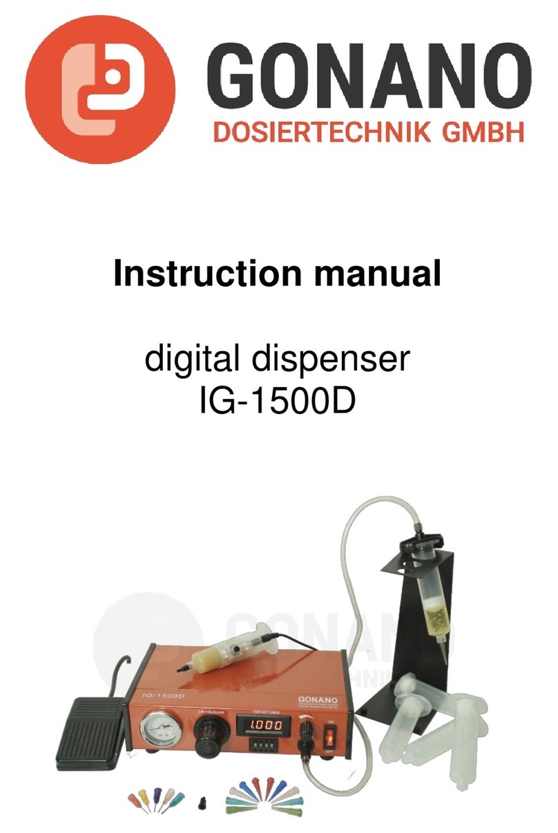
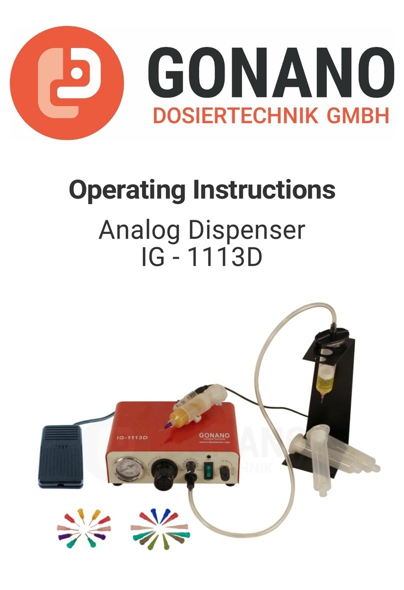
GONANO IG-101D User manual

Operating Instructions
Digital Dispenser
IG - 101D

Operating Instructions IG-101D
2
Content
1 General information 3
1.1 The IG-101D 3
1.2 Intended Use 3
2 Scope of delivery 4
3 Safety instructions 6
3.1 General safety information 6
3.2 Dangers for the operator 6
3.3 Electrical safety instructions 6
3.4 Safety Instructions for Auxiliary- and Operating Materials 6
4 About your dispensing unit 7
5 Commissioning 8
5.1 Connecting the device 8
5.2 Connection diagram 9
6 Operation 10
6.1 The different operating modes 10
6.2 Setting the dispensing time 11
6.3 Saving the dispensing time 11
6.4 Setting the waiting time 12
6.5 Saving the waiting time 13
6.6 Loading the dispensing and waiting time 13
6.7 Starting the dispensing process 14
6.8 Ending the dispensing operation 14
7 Pressure monitoring 15
7.1 Calling up the pressure monitoring menu 15
7.2 Setting the pressure display unit 15
7.3 Setting the minimum pressure for pressure monitoring 16
8 Differnt Variants 16
9 Maintenance and Cleaning 17
10 Disposal 17
11 Technical data 18
12 Declaration of Conformity 19

Operating Instructions IG-101D
3
1 General information
Dear customer,
Thank you for choosing our model IG-101D dispensing controller.To
ensure proper operation, please carefully read the following pages for
correct operating and maintenance instructions. Keep these instructions
handy for future reference. If you require further information or if you have
any questions please contact us directly.
1.1 The IG-101D
The IG-101D dispensing controller series consists of two models which
have an output pressure of 0-1 and 0-7 bar respectivly, with no other
differences. For this reason, only the model IG-101D is referred to below.
The IG-101D is used for the precise dispensing of various liquids and
pastes. The operation is achieved by using compressed air along with
utilizing dispensing systems, such as small barrels containing 3 to 75 cc
of material. With the units compressed air regulator, the dispensing
pressure can be applied to the material and can be adjusted exactly to
dispense the correct amount of material.
In conjunction with the unit precise timer, distinct and precise amounts of
material can be dispensed. A digital pressure monitor controls the inlet
pressure.The process accuracy and reliability is additionally increased
with an adjustable minimum pressure device.
1.2 Intended Use
The device is designed and constructed for commercial use. It is only to
be used for dispensing liquid and paste materials such as adhesives,
lubricants, various pastes, grease, oil, silicone and other similar materials.
Any other use is considered improper. If this device is used for other
purposes, personal injury or damage to property may result. The
manufacturer assumes no responsibility for consequences resulting from
improper use of the unit.
Non-intended use, which would also void the warranty, includes:
• Changes to the device not expressly recommended in the operating
instructions • Modifications to the unit and its components • Use of
incompatible or damaged spare parts • Use of non-approved accessories
or auxiliary equipment • Exceeding the approved and recommended
pressures

Operating Instructions IG-101D
4
2 Scope of delivery

Operating Instructions IG-101D
5
Accessories 0-7 Bar
Quantity Designation Article Number
5 Syringe barrale 30cc IP1E30
5 Piston PE 30cc IP2E30/55
Tapered tip set consisting of:
2 Tapered tip/light green IP510
2 Tapered tip/light orange IP511
2 Tapered tip/light blue IP513
2 Tapered tip/olive IP514
2 Tapered tip/gray IP516
2 Tapered tip /green IP518
2 Barrel tip cap/clear IP700-CLEAR
Dispensing tip set 1/2" standard consisting of:
2 Dispensing tip/green IP718050
2 Dispensing tip/pink IP720050
2 Dispensing tip/violett IP721050
2 Dispensing tip/orange IP723050
2 Dispensing tip/red IP725050
Accessories 0-1 Bar
Quantity Designation Article Number
5 Syringe barrale 30cc IP1E30
5 Piston PE 30cc IP2E30/55
Tapered tip set consisting of:
2 Tapered tip/gray IP516
2 Tapered tip/green IP518
2 Tapered tip/pink IP520
2 Tapered tip/blue IP522
2 Tapered tip/red IP525
2 Tapered tip/clear IG-TN27
2 Barrel tip cap/clear IP700-CLEAR
Dispensing tip set 1/2" standard consisting of:
2 Dispensing tip/red IP725050
2 Dispensing tip/clear IP727050
2 Dispensing tip/lavender IP730050
2 Dispensing tip/yellow IP732050
2 Dispensing tip/light green IP734050

Operating Instructions IG-101D
6
3 Safety instructions
3.1 General safety information
If this device is used for purposes other than those described in this
operating manual, personal injury or damage to property may result.
Only use the device in accordance with the enclosed instructions.
3.2 Dangers for the operator
• Read the operating instructions carefully before use.
• Always wear suitable protective clothing and eye wear.
• Smoking or open flames are strictly prohibited when dispensing any
type of flammable liquid or paste.
• This device is intended for indoor use only.
3.3 Electrical safety instructions
• Before opening the dispensing unit, disconnect it from the power
supply by disconnecting the input power cord.
• Failure to disconnect input power may risk electrical shock.
• The unit may only be opened by a trained and authorized electrical
personnel.
• Operate the device exclusively within the maximum permitted rated
power / settings.
3.4 Safety Instructions for Auxiliary- and Operating Materials
For details on proper handling and safety precautions, for materials to be
dispensed ALWAYS check the Material Safety Data Sheet (MSDS).

Operating Instructions IG-101D
7
4 About your dispensing unit

Operating Instructions IG-101D
8
5 Commissioning
5.1 Connecting the device
• Unpack the dispensing controller and set it up on a worktable where it
will be used. Preferably in a dry location.
• Using the airline hose supplied with the unit, connect the compressed
air inlet [11] on the back of the dispensing unit to your compressed air
supply. Make sure to supply the device with clean dry air only.
• Connect the power cable to the power connection [12] on back of the
unit.The unit can be operated either by finger switch, foot switch or a
control cable, if the dispensing controller is to be integrated with a
dispensing robot. All these cables are inserted into the socket for the
foot switch on the back of the unit. [8]
• Switch on the controller. First all LEDs on the front of the unit will light
up briefly. [6] Once only one of the mode LEDs is lit up, the unit is ready
for operation.
• Seal a barrel filled with dispensing material using the barrel adapter by
placing the adapter across the barrel and then locking it with a 90°
turn.
• Select a suitable luer lock dispensing needle and attach it onto the
barrel.
• Connect the hose of the barrel adapter to the compressed air outlet [5]
of the IG-101D and set the pressure
with the pressure regulator [3].
Select a low dispensing pressure at the beginning and then increase it
step by step.
• Test your setup by pressing the MODE button several times until the
MANUAL LED lights up and then press the PURGE button. If everything
is connected correctly, the set dispensing pressure now pushes
material out of the front of the dipensing needle, until you release the
PURGE button.

Operating Instructions IG-101D
9
5.2 Connection diagram
If you have connected all your air lines and wiring correctly your system
setup will look something like this:

Operating Instructions IG-101D
10
6 Operation
6.1 The different operating modes
The IG-101D has three different operating modes, which can be selected
with the MODE button.
The mode that is set is indicated by an illuminated status LED.
MANUAL Mode
In the manual mode (MANUAL) you control the dispensing unit with the
foot switch or finger switch (optional) or by pressing the PURGE key . The
unit dispenses the material as long as you hold down the switch or the
button.
TIMER Mode
In the time control mode (TIMER), the device dispenses the material for
the duration of a preset time. This mode is useful if you want to dispense
the same amount of material several times in the operation.
CYCLE Mode
In the cycle mode (CYCLE), the dispensing device continuously carries out
a sequence of dispensing and wait "steps". The CYCLE mode can be used
if the work piece has to be changed or the material is to be dispensed to
another location.
In the cycle mode the dispenser waits a specified time before resuming
the dispensing of the material. First, the duration of the dispensing is set
in the TIMER operating mode. In the CYCLE mode, the wait time is then
defined .

Operating Instructions IG-101D
11
6.2 Setting the dispensing time
Press the MODE button to switch to the TIMER mode.To set a dispensing
time, press the SET button.
The right most digit of the 4-digit display will start to flash.
Then set the desired numerical value with the arrow up (
⇧
) and arrow
down (
⇩
) keys. The next decimal place can be reached by pressing the
Arrow-left key (
⇦
).
Set all four digits of the display as desired. You can then change the
position of the decimal point by pressing the left arrow key (
⇦
) to select.
(123 seconds thus become 12 .3 or 1 .23 or 0 .123 seconds)
Exit the settings by pressing the EXIT button
6.3 Saving the dispensing time
Press and hold the MEM button for 2 seconds. The display changes to "Ld
1" and the letters Ld flash briefly.
Press the MEM button again to switch to the memory locations. The
display shows "Sv 1".
Use the arrow up (
⇧
) and arrow down (
⇩
) keys to select one of nine
memory locations. (Sv 1 to Sv 9)
Press the EXIT key to save the dispensing time and return to the TIMER
mode.

Operating Instructions IG-101D
12
6.4 Setting the waiting time
Press the MODE button to switch to CYCLE mode.
To set a waiting time, press the SET button at which point the right most
digit of the 4-digit of the digital display will start to flash.
Set the desired numerical value with the arrow up (
⇧
) and arrow down (
⇩
)
keys.6
The next decimal place can be reached by pressing the Arrow-left key (
⇦
).
Set all four digits of the display as desired.
You can then change the position of the decimal point by pressing the left
arrow key (
⇦
) to select. (123 seconds thus become 12 .3 or 1 .23 or 0 .123
seconds)
Exit the settings by pressing the EXIT button .
It often makes sense to save a manually determined dispensing time as
a program. To do this, simply press the foot switch in MANUAL mode
until the desired amount of material has been dispensed. At this point,
the digital display shows the elapsed dispensing time. This is displayed
by pressing the MEM button in the TIMER mode . Now this setting can
be saved in a specific memory location.

Operating Instructions IG-101D
13
6.5 Saving the waiting time
Press and hold the MEM button for 2 seconds. The display changes to "Ld
1" and the letters Ld flash briefly.
Press the MEM button again to switch to the memory locations.The
display shows "Sv 1"
Select one of the nine memory locations (Sv 1 to Sv 9) with the arrow up
(
⇧
) and arrow down (
⇩
) keys.
With the EXIT key you save the waiting time and return to the CYCLE
mode.
6.6 Loading the dispensing and waiting time
To load a dispensing time from the memory, switch to the TIMER mode
with the MODE button. Press and hold the MEM button for 2 seconds.
The display changes to "Ld 1" and the letters Ld flash briefly.
Select one of the nine memory locations (Ld1 to Ld9) with thearrow up (
⇧
)
and arrow down (
⇩
) keys With the key EXIT the value is loaded. The
instrument returns to the TIMER mode.
To load a waiting time from the memory, switch to CYCLE mode with the
MODE button.
When loading the waiting time, proceed as for loading the dispensing
time.
Press the EXIT key to load the value. The instrument returns to TIMER
mode.
The IG-101D has a total of nine memory locations. It is important to store
the "waiting time" setting in a different memory location than the
"dispensing time" setting.

Operating Instructions IG-101D
14
A dispensing operation in the CYCLE mode must be stopped again as it is
a cycle of the dispensing time and waiting time . (see 6.8)
6.7 Starting the dispensing process
The dispensing process can be started in various ways.
In the MANUAL mode, press and hold the foot switch, finger switch or
PURGE button for the desired dispensing duration.
In the TIMER and the CYCLE modes, start the dispensing process by
pressing the foot switch, finger switch or PURGE key once.
6.8 Ending the dispensing operation
In the MANUAL and TIMER operating modes, the dispensing process is
stopped by releasing the previously selected switch or the button.
In CYCLE mode, the cycle is stopped during the set pause time by
pressing the foot or finger switch or by pressing the PURGE key. Using
the MODE key, it is possible to stop the CYCLE mode during the set
dosing time.

Operating Instructions IG-101D
15
7 Pressure monitoring
Your dispensing unit is equipped with a monitoring device for the input air
pressure. If there is a drop in pressure or if the pressure falls below the
preset pressure level, the device does not allow any further dispensing
operations and the message "P-AL" (Pressure Alarm) appears on the
digital display.
In this way, incorrect dispensing can be avoided.
Only after the minimum pressure has been reached, can dispensing be
resumed.
The pressure monitoring can be set to values between 0 .1 and 9 .9 bar or
0 and 143 PSI.
7.1 Calling up the pressure monitoring menu
To access the pressure monitoring menu, while the instrument is switched
on, press and hold the SET and MEM buttons.
The digital display now shows the unit for the pressure indication ("bar" or
"PSI").
7.2 Setting the pressure display unit
Use the arrow up (
⇧
) and arrow down (
⇩
) keys to set the desired unit for
pressure.
Press the PURGE key to accept the value. You can now continue to set a
pressure limit.
Pressing the EXIT key the values are accepted and the device restarts.

Operating Instructions IG-101D
16
7.3 Setting the minimum pressure for pressure monitoring
After confirming the pressure, you can set a value for the minimum
pressure with the arrow up (
⇧
) and arrow down (
⇩
) keys.
Press the EXIT key to accept the value and restart the instrument.
8 Differnt Variants
In order to deactivate the pressure alarm, the minimum pressure can be
set to 0.0.
Variant 0-7bar:
• For medium to high viscosity materials
• For bigger dispensing amounts
• Materials: silicones, thermal paste, PU, etc.
Variant 0-1 bar:
• For low viscosity materials
• For smaller dispensing amounts
• Materials: cyanoacrylate, anaerobic glue, oils, uv-glue, SMD-glue

Operating Instructions IG-101D
17
At the end of its service life, dispose of the controller in accordance with
the applicable local regulations.
Electrical parts cannot be disposed of with household waste.
According to Directive 2012/19/EU on Waste Electrical and Electronic
Equipment (WEEE), electrical equipment must be returned to the collection
points set up for this purpose in order to be reused.
The dispensing controller is maintenance-free. Any needed repairs must
be performed by the manufacturer.
To clean the unit and the housing, use only dry or damp cloths and never
use cleaning fluids such as petrol, thinners or any other flammable or
corrosive liquid.
9 Maintenance and Cleaning
10 Disposal

Operating Instructions IG-101D
18
11 Technical data
Outer dimensions (D x W x H) 235 x 210 x 75 mm incl. Pressure
regulator
Weight ca.1,30 kg
Power supply 85 – 264 V AC 50/60 Hz
Internal voltage 24 V DC
Dispensing duration 0,01 bis 9999 seconds
Compressed air input 0 - 7 bar
Compressed air Output 0 - 7 bar / 0 - 1 bar
Digital display 7 segment display 4-digit
Programs 9 memory slots
Operation mode manual / timer
Vacuum retention yes
Available models 0 - 1 bar, 0 - 7bar

Operating Instructions IG-101D
19
12 Declaration of Conformity
Product:
Dispensing Controller
Modell:
IG-101D
IG-101D-0-1-BAR
Parameter:
85-264V AC, 50/60Hz, 15W
_________________________________________________________________________________
We confirm that the design and construction of the above-mentioned products comply with the
provisions of the European Community directives listed below and the requirements for obtaining a CE
mark.
EC Directive Electromagnetic Compatibility 2014/30/EU
EN 61000-6-3: 2007/A1: 2011/AC: 2012
EN 61000-6-2: 2015
EC Low Voltage Directive 2014/35/EU
This declaration is made responsible for the following importer:
Company:
GONANO Dosiertechnik GmbH
Address: Franzensdorfer Strasse 40
2285 Breitstetten
AUSTRIA
Phone: 0043-2216-8478
E-mail: office@dosieren.net
Breitstetten, 14.02.2022 Doris Holda, Managing Director
Table of contents
Other GONANO Dispenser manuals