Gonotec OSMOMAT 050 User manual

www.gonotec.com
User Guide
Colloid Osmometer / Oncometer
OSMOMAT® 050
Osmolality Measurement in medical and pharmaceutical field


Handbuch OSMOMAT 050 Seite 3 von 51
Version 1.1 (2011-10-12)
Notes, Safety Notices and Warnings
The symbols nd bbrevi tions defined below m y ppe r on the p ck ging m teri l, on the seri l
number pl te or in the oper ting instructions:
In-vitro di gnostic device
This product meets the requirements of
EEC Directive 98/79 rel ting to in-vitro di-
gnostic devices.
Attention (refer to document tion)!
Ple se follow the s fety notices in the
equipment oper ting instructions.
“Use by ” The d te th t follows indic tes
the expir tion d te s year-month.
The n me of the product b tch follows.
REF
Article number or order number
The following p ges provide step-by-step introduction to using, m int ining nd servicing the me s-
urement equipment. P ss ges requiring speci l ttention re m rked s follows:
This symbol w rns of the d nger of corrupt-
ing me surement results, for ex mple, by
improper use of the me suring cell.
This symbol w rns of the d nger of d m g-
ing the unit or the me surement system, for
ex mple, s result of improper servicing.
Subject to errors and technical changes.
The information contained in this document may be changed without prior notice.
© 011 Gonotec Gesellschaft für Meß- und Regeltechnik mbH. All rights reserved.
Reproduction of this document in ny form is permissible only with the prior written consent of Gonotec Gesellsch ft für Meß-
und Regeltechnik mbH.
Tr dem rks used in this document: GONOTEC nd OSMOMAT re tr dem rks of Gonotec Gesellsch ft für Meß- und Regel-
technik mbH.
Other tr dem rks nd tr de n mes used in this document m y be tr dem rks or n mes of the corresponding comp nies or
their products. Gonotec Gesellsch ft für Meß- und Regeltechnik mbH does not ssert ny cl im to tr dem rks or tr de n mes
other th n its own.

Seite von 51 Handbuch OSMOMAT 050
Version 1.1 (2011-10-12)
Table of contents
1
Introduction ....................................................................6
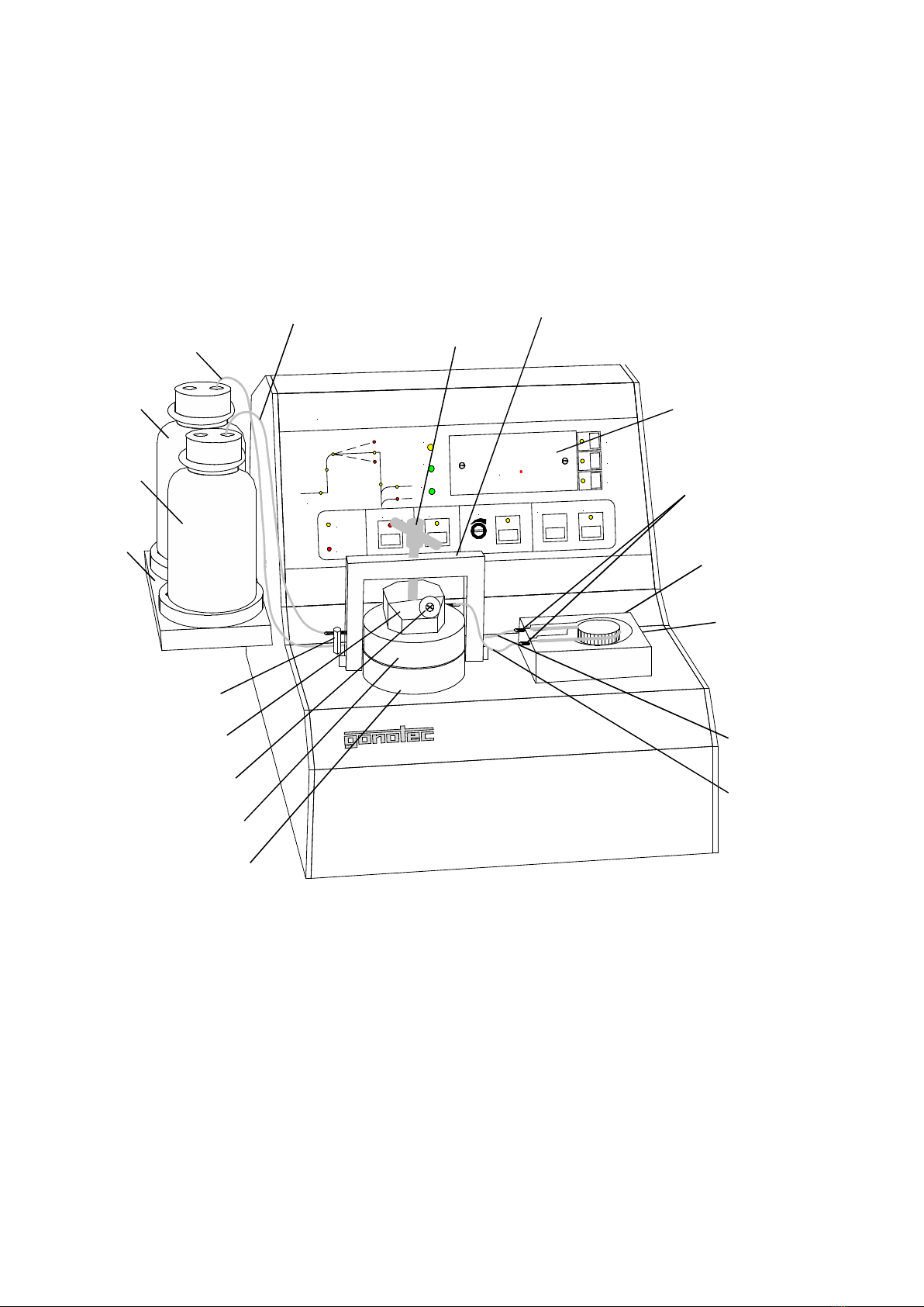
Overview of the OSMOMAT 050 .................................10
3
Setup and Initial Operation .........................................13
4
Preparing the Measuring cell for Measurement .......15
4.4.1
Selecting suit ble membr nes ............................................................................................. 18
4.4.2
Conditioning the membr ne ................................................................................................. 19
4.6.1
Initi l St rtup with Dry Me suring cell .................................................................................. 21
4.6.2
Removing the Membr ne When the Me suring cell is Filled ............................................... 21
5
Calibrating the OSMOMAT 050 ................................... 6
6
Measuring the Colloid Osmotic Pressure ................. 8
1.1
Applic tions of the OSMOMAT 050 ....................................................................................... 6
1.2
Applic tion Restrictions of the OSMOMAT 050 ..................................................................... 7
1.3
Me surement Method of the OSMOMAT 050 ....................................................................... 7
1.4
Reproducibility of the OSMOMAT 050 ................................................................................... 8
1.5
Unp cking the OSMOMAT 050 Colloid Osmometer ............................................................. 9
1.6
P ck ging Contents ............................................................................................................... 9
2.1
Overview of Displ y nd Connectors ................................................................................... 10
2.2
Power Supply ....................................................................................................................... 12
2.3
Dimensions nd Weight ....................................................................................................... 12
2.4
S fety nd H ndling Inform tion .......................................................................................... 12
2.5
Known Risks Associ ted with the Use of the OSMOMAT 050 ............................................ 12
4.1
M king the Tube Connections during Initi l St rtup ............................................................ 15
4.2
Ringer's Solution s Solvent ................................................................................................ 17
4.3
Filling the Supply nd W ste Bottles ................................................................................... 18
4.4
Prep ring the Semiperme ble Membr ne ........................................................................... 18
4.5
Prep ring the Filter P per nd Deg ssing the Solvent ........................................................ 20
4.6
Opening the Me suring cell ................................................................................................. 21
4.7
Cle ning nd Filling the Lower H lf of the Me suring cell ................................................... 21
4.8
Screwing Together the Me suring cell................................................................................. 23
5.1
C libr tion Using the Hydrost tic Pressure Difference ........................................................ 26
6.1
Prerequisites for Me surement ............................................................................................ 28
6.2
S mple M teri l ................................................................................................................... 29
6.3
Displ y of the OSMOMAT 050 ............................................................................................. 29
6.4
Performing the Me surement .............................................................................................. 30
6.5
Recording nd Storing the Second Me surement V lue ..................................................... 32

Handbuch OSMOMAT 050 Seite 5 von 51
Version 1.1 (2011-10-12)
7
Classification of Malfunctions ...................................35
8
Maintenance of the OSMOMAT 050 ...........................38
9
Appendix ......................................................................41
10
Limited Warranty .........................................................43
11
Returning Parts for Warranty .....................................44
1
Specifications of the OSMOMAT 050 .........................45
13
Service Instructions for Replacing a Defective
Pressure Transducer ...................................................46
13.2.1
Dis ssembly ......................................................................................................................... 47
13.2.2
Assembly .............................................................................................................................. 49
8.1
Requirements of the Medic l Devices Oper tor Ordin nce ................................................ 38
8.2
S fety Checks (§ 6 of Medic l Devices Oper tor Ordin nce) ............................................. 38
8.3
Me surement Checks (§ 11 of Medic l Devices Oper tor Ordin nce) ............................... 38
8.4
Intern l Qu lity Control of the OSMOMAT 050 ................................................................... 39
8.5
Repl cing Defective Power Fuse ...................................................................................... 39
8.6
Forfeiture of Me surement System W rr nty ...................................................................... 39
8.7
Specific tions for RS 232 Interf ce ...................................................................................... 40
8.8
Tr nsmission Softw re ........................................................................................................ 40
9.1
Consum bles ....................................................................................................................... 41
9.2
Accessories nd Sp re P rts ............................................................................................... 41
9.3
Cl ssific tion of the IVD ....................................................................................................... 42
9.4
EC Compli nce St tement - OSMOMAT
®
050 .................................................................... 42
9.5
Provisions of Certific tion .................................................................................................... 42
11.1
Rep ir or Credit .................................................................................................................... 44
11.2
Before C lling Gonotec ........................................................................................................ 44
13.1
When is repl cement of the pressure tr nsducer required? ............................................. 46
13.2
Instructions ........................................................................................................................... 47

Page 6 of 51 OSMOMAT 050 User Guide
Version 1.1 (2011-10-12)
1 Introduction
1.1 Applications of the OSMOMAT 050
The Gonotec OSMOMAT
®
050 colloid osmometer is non-inv sive in vitro di gnostic device for in-
vitro n lysis of hum n blood nd other s mples. Its purpose is to provide inform tion to help identify,
di gnose, monitor nd tre t physiologic l conditions, st tes of he lth, nd dise ses.
The equipment may only be operated by specialists or those persons whose training or skills
have provided them with the necessary practical experience (see MPBetreibV: German Medical
Devices Operator Ordinance).
The OSMOMAT 050 colloid osmometer is p rticul rly suited for routine me surements in medic l
pplic tions s well s the molecul r weight determin tion in queous solutions in industry nd re-
se rch pplic tions. The OSMOMAT 050 colloid osmometer determines the colloid osmotic pressure
(COP) of blood pl sm . The m in di gnostic consider tions for determining the colloid osmotic pres-
sure in medic l pplic tions pply e.g. in c se of blood loss, hyper lbuminemi , s well s in lbumin
ther py to prevent lung edem s nd ll dise ses resulting in ch nges to the colloid osmotic pressure.
Approx. 150 µL of s mple solution re required, m king it suit ble for me suring even sm ll s mple
volumes. The me suring speed permits r pid series me surements.
In the hospit l, the colloid osmotic pressure is n import nt p r meter mong others for monitoring
infusion- nd dilution ther pies nd for di gnosing nom lies in the w ter b l nce thus supporting
decisions with respect to ddition l ex min tions.
The OSMOMAT 050 h s been pplied successfully in the following fields:
Clinic l pedi trics Urology
Anesthesi / intensive c re medicine Nephrology
C rdiology Bot ny
Gynecology Clinic l chemistry
Physiology nd m ny more

OSMOMAT 050 User Guide Page 7 of 51
Version 1.1 (2011-10-12)
1. Application Restrictions of the OSMOMAT 050
The OSMOMAT 050 is not suit ble for me suring whole blood s mples.
1.3 Measurement Method of the OSMOMAT 050
The me surement principle of the OSMOMAT 050 is b sed on me suring cell, consisting of n up-
per nd lower h lf, e ch with volume of pprox. 10 µL, sep r ted by semiperme ble membr ne
(Fig. 1-1). The so-c lled reference cell, loc ted below the membr ne, is equipped with pressure
tr nsducer (pressure converter, me suring bridge). The upper h lf of the me suring cell, lso known
s s mple cell, is connected to the utom tic rinsing mech nism. In st ndby st te, both cells cont in
solvent (such as Ringer's solution, isotonic NaCl solution to prevent pressure drops nd ensure th t
the pressure me surement membr ne is rel xed.
After dding s mple with higher colloid osmotic (oncotic) pressure (e.g. serum or pl sm ) to the
s mple cell, perme tion of solvent c uses underpressure in the reference cell b sed on the l ws of
osmosis (bec use the membr ne is impenetr ble to proteins, this c n only be chieved by flow of
solvent). This is me sured by pressure tr nsducer, mplified electronic lly, nd displ yed s posi-
tive, direct colloid osmotic pressure (COP v lue), either in mm Hg (mm of mercury), cm H
2
O, or k-
P sc l. By def ult, the re ding is displ yed in mm Hg. The me surement unit c n be switched by
pressing the corresponding buttons on the digit l displ y.
Different types of semiperme ble membr nes with v rying perme bility ("pore size") c n be used for
m cro molecules with different molecul r weights. This results in ch r cteristic reference number for
e ch type of membr ne (the so-c lled "membr ne cut-off", indic ted in d lton units). Membr nes with
cut-off of 10,000 or 20,000 d lton h ve proven to be very useful in pr ctic l pplic tions.
S mple cell
Semiperme ble membr ne
Reference cell
Pressure tr nsducer
Amplifier Displ y
Figure 1-1: Schematic figure of the measuremet principle

Page 8 of 51 OSMOMAT 050 User Guide
Version 1.1 (2011-10-12)
1.4 Reproducibility of the OSMOMAT 050
Me surement displ y 3 digits
Me suring r nge 73 mm HG, 100 cm w ter column, or 9.99 kP
Resolution 0.1 mm HG over the entire me surement r nge
Reproducibility < ±0.5 mm HG

OSMOMAT 050 User Guide Page 9 of 51
Version 1.1 (2011-10-12)
1.5 Unpacking the OSMOMAT 050 Colloid Osmometer
The OSMOMAT 050 should be unp cked immedi tely upon receipt nd checked for obvious signs of
d m ge sust ined during shipping. If ny d m ge is found, notify the m nuf cturer:
Gonotec GmbH
GSG-Hof
Reuchlinstr. 10-11
D-10553 Berlin
Tel.: (030) 7809588-0
F x: (030) 7809588-88
E-m il: cont ct@gonotec.com
Web: www.gonotec.com
Toll-free service number for Germany: 0800 / 78460 7
The reus ble p ck ging for this equipment w s speci lly designed to ensure s fe nd hygienic
tr nsport. Please save the packaging in case the unit needs to be shipped back to Gonotec for
rep ir or servicing.
1.6 Packaging Contents
Check to m ke sure the contents of your shipment re complete. We c nnot ccept responsibility for
ny missing items reported t l ter d te.
Accessories and consumables included in the shipment
Item number
20.9.0100 1 power cord
20.9.0160 1 RS-232 c ble
1 p ck ge of sm ll p rts including:
00.9.0102
00.9.0104
50.9.0040
50.9.0060
50.9.0070
50.9.0030
2 fine-wire fuses
30V 50mA
(
(at 110V 0.5A
1 sm ll O ring (26 x 2 mm
2 pump tubes (9.5 cm
2 tube nipples
10 silicon sept
50.9.0020 1 p ck ge cont ining 5 membr nes
0,000
dalton
50.9.0160 1 p ck ge cont ining 2 plungers
50.9.0100 1 precision syringe 250 µL
50.9.0150 1 tweezers
50.9.0140 1 tool for widening the tube ends
50.9.0180 1 bottle of cle ning solution
1 p ck ge cont ining:
50.9.0080
50.9.0090
1 tuberculin syringe (pl stic) with speci l c nnul (16 mm
1 pl stic syringe (30 mL) with pump tube nd cl mp
50.9.0130 2 pl stic bottles, l beled (Ringer's solution and waste
1 user guide 050

Page 10 of 51 OSMOMAT 050 User Guide
Version 1.1 (2011-10-12)
3
4
5
6
7 8
Overview of the OSMOMAT 050
.1 Overview of Display and Connectors
Fig. -1: Front view of OSMOMAT 050
1
k-PASCAL
cm H2O
mm Hg
OVER LOAD
START
RESULT CHECK
CALIBRATION
MEASURING
SE
RIE
S
RINSING
RESET
2 RE
SULT
RESULT
INJECT
BUSY
STAND BY
OSMOMAT 050
Colloid Osmometer
2
3
.
2
Connection tube
between supply bottle nd
upper h lf of me suring cell
Bottle tr y
Supply bottle
W ste bottle
Connection tube
between w ste bottle
nd ground nipple
Leveling disk
Lower h lf of me suring cell
Septum screw
Ground nipple
Upper h lf of me suring cell
Tension screw
Cl mping yoke
Tube nipples
Tube pump
Tube for
tube pump
Digit l displ y
Connection tube
between pump nd upper
h lf of me suring cell
Connection tube
between pump nd
ground nipple

OSMOMAT 050 User Guide Page 11 of 51
Version 1.1 (2011-10-12)
Fig. - : Rear view of the Osmomat 050
Power connection
Fuse holder for two-
ph se fuse protection
of power supply
Ch r cteristics for
device fuse to be used
M nu l pump
control
RS232 output
An log output
Alignment
potentiometer
for n log port
Seri l number pl te with inform tion on
seri l number, power volt ge, frequency
nd power consumption
Power switch
1/on 0/off
Sicherungen / Fuse
110 V - 500 mA LAG
230 V - 250 mA LAG Fuse
0
I
4
3
2
15
Recorder Output
Pumpe

Page 12 of 51 OSMOMAT 050 User Guide
Version 1.1 (2011-10-12)
. Power Supply
The st nd rd model is oper ted with 230V (+/- 30V) t 50/60 Hz. The power consumption is 20VA.
Speci l models using 115V or 100V re lso v il ble.
.3 Dimensions and Weight
Dimensions (width x height x depth):
360 x 250 x 355 mm
Weight:
pprox. 5.1 kg excluding bottles
.4 Safety and Handling Information
The OSMOMAT 050 colloid osmometer is n electric l bor tory me surement device. It should there-
fore be h ndled ccording to the s fety provisions nd prec utions for electric me surement, control,
nd l bor tory equipment.
If the equipment is to be decommissioned, m ke sure it is sufficiently disinfected. This will
m ke sure th t the equipment h s been decommissioned in ccord nce with loc l ccident
prevention guidelines (UVV).
To prevent d m ge to the pressure tr nsducer during extended periods of in ctivity or in c se of de-
commissioning, the following steps must be performed:
Alw ys switch on device when performing work on the me suring cell or the pressure tr ns-
ducer (see ch pter 3).
Open me suring cell nd remove membr ne nd filter p per.
Repe tedly rinse me suring cell using distilled w ter (especi lly the pressure tr nsducer).
Suction off residu l w ter using speci l c nnul , dry cell by using p per, nd loosely repl ce
screw c p with dry filter p per inserted.
The unit does not emit h rmful subst nces either during oper tion or when switched off.
Symbols on the unit nd seri l number pl te correspond to the requirements of the following st nd-
rds: DIN EN 61010-1, DIN EN 375 nd DIN EN 980 (h rmonized st nd rd for medic l devices c-
cording to § 3 No. 17 of the Germ n Medic l Device L w MPG).
.5 Known Risks Associated with the Use of the OSMOMAT 050
In our experience using the OSMOMAT since 1979, we h ve not found it to present ny direct h z rds
or risks to the user. Such h z rds nd risks c nnot be excluded entirely for technic l equipment, how-
ever.
This oper ting instruction helps you g in b sic underst nding of the design, the me surement prin-
ciple, m inten nce nd servicing of the unit.

OSMOMAT 050 User Guide Page 13 of 51
Version 1.1 (2011-10-12)
3 Setup and Initial Operation
The unit must be pl ced in loc tion ree rom vibrations nd must be protected from direct sources
of he t such s sunlight, he ters or furn ces. The mbient temper ture should be between 10°C nd
35°C (50-95°F).
It is strictly necess ry to pl ce the device on very sturdy surf ce. Otherwise, the sensitive pressure
me surement nd the utom tic end point detection m y be disturbed.
Use the power cord provided to connect the OSMOMAT 050 from the power connector on the b ck of
the unit to power outlet. M ke sure the unit’s ground is en bled vi the shockproof grounding.
If the power cord plug does not m tch the convention l power outlets in your loc tion, you m y substi-
tute nother power cord. It is essenti l, however, th t the c ble’s green/yellow wire is connected to the
s fety grounding.
It is also important to ensure that the voltage indicated on the serial number plate
matches that o your electricity network. Incorrect voltage will cause the use in the
power supply unit to blow.
The OSMOMAT 050 c n now be switched on vi the power switch on the b ck of the unit (next to the
power connector).
All work (unscrewing, screwing together or adding solvents) must only be per ormed
with the device switched on and in calibration mode (can be set by pressing the “CALI-
BRATION” button).
Excess pressure which m y result in the destruction of the pressure tr nsducer is indic ted on the
displ y. This h ppens in three st ges. In the first st ge, the displ y shows 99.9 nd fl shes. If the
pressure incre ses, the "overlo d" LED lights up in the second st ge. If the pressure still incre ses, n
l rm sounds. When the l rm sounds, the pressure g uge is t pprox. 50% of the burst pressure. If
you continue to screw together or open the system, the highly sensitive pressure tr nsducer will be
destroyed.
The WARRANTY is voided or a pressure transducer destroyed due to over- or underpressure.
Before beginning an initial measurement, you must add solvent to the measuring cell, insert
the prepared membrane, and calibrate the device (see chapter 4 and 5).
When the me suring cell is filled nd the membr ne is inserted, the device is in st ndby mode nd
re dy for me surement, indic ted by the green st ndby-LED.
You c n st rt the me surement by pressing the “START” button. This will check the zero point inter-
n lly nd prompt the user to inject the s mple fter pprox. 10 seconds (indic ted by the fl shing IN-
JECT LED nd the LED on the me suring cell).
The device should lw ys rem in switched on while the me suring cell is filled nd closed, even if it is
not used for n extended period of time. The system utom tic lly rinses the me suring cell t regul r
interv ls, keeping the OSMOMAT 050 re dy for me surement.

Page 14 of 51 OSMOMAT 050 User Guide
Version 1.1 (2011-10-12)
While the device is not in use, the measuring cell may dry out, especially in the area o
the pressure transducer. The salt crystals that orm adhere to the pressure measure-
ment membrane and can destroy it. Regular rinsing prevents the drying out.
M ke sure to top off the Ringer's solution nd empty the w ste bottle regul rly.
I the device is le t in standby mode or an extended period o time without topping o
the Ringer's solution, the measuring cell will dry out quickly, which may result in the
destruction o the pressure measurement membrane.
I the device is not used or an extended period o time (several weeks), the measuring
cell must be opened and rinsed using distilled water. A terwards, the device can be
switched o .
When When working on the pressure transducer, the device must always be switched on.

OSMOMAT 050 User Guide Page 15 of 51
Version 1.1 (2011-10-12)
4 Preparing the Measuring cell for Measurement
To prep re the me suring cell, you need the tools nd ccessories included with the st nd rd cces-
sories s well s suit ble solvent, distilled w ter nd the prep red semiperme ble membr ne nd
filter p per (see chapter 4.4).
4.1 Making the Tube Connections during Initial Startup
The tubes included with the st nd rd ccessories re connected ccording to Figure 4-1: Making the
tube connections.
Figure 4-1: Making the tube connections
Use only the Tygon tubes supplied by the manu acturer. Other tubing material is per-
meable to air, which causes air bubbles that may severely impact or prevent the
measurement.
Bore for pressure
compens tion
Ringer's solution
Supply bottle
plunger
W ste, minimum
fill level 1 cm
W ste bottle
plunger
Connection tube between
ground nd w ste bottle Connection tube between
supply bottle nd pump
Ground
Connection tube between me suring cell
nd ground
Upper me suring cell
T screw
Lower me suring cell
Septum screw
Tube nipples
Connection tube between pump
nd me suring cell
Tube pump
Pump tube

Page 16 of 51 OSMOMAT 050 User Guide
Version 1.1 (2011-10-12)
The tubes re pushed onto the st inless steel tubes by bout 5 mm. The tool for widening the tube
ends (50.9. 0140) included with the st nd rd ccessories is used for this purpose. The tube end is
held using s ndp per nd widened using the moistened tip of the tool.
The connection tubes for the supply nd w ste bottles re p ssed through bore of the unscrewed
c p nd pushed onto the corresponding plungers (Figure 4- ). The plungers hold the tubes on the
bottom of the bottles. The second opening on the c p provides unrestricted tmospheric pressure
compens tion.
Figure 4- : Plunger
Tube lengths
Connection tube between supply bottle nd pump 59 cm
Connection tube between ground bolt nd w ste bottle 45 cm
Connection tube between pump nd me suring cell 6 cm
Connection tube between me suring cell nd ground bolt 5 cm
Pump tube 9,5 cm
Table 4-1 Tube lengths

OSMOMAT 050 User Guide Page 17 of 51
Version 1.1 (2011-10-12)
4. Ringer's Solution as Solvent
The Ringer's solution should be pure Ringer's electrolyte solution without dded l ct tes or other
subst nces. If necess ry, the solution c n be self m de.
Sodium chloride 0,8 g
Pot ssium chloride 0,02 g
C lcium chloride 0,02 g
Sodium bic rbon te 0,1 g
use distilled w ter to fill up to 100 cm³
In exception l c ses, you c n lso use n isotonic s line solution with concentr tion of 0.9% NaCl.
The solvent used for prep ring the lower h lf of the me suring cell must not cont in ny mount of
solved g s/ ir. If necess ry, it must first be deg ssed by he ting up just under the boiling point or by
deg ssing under v cuum. We recommend using the 30 mL plastic syringe included in the ccessories
for simple w y to deg s the solvent ( Figure 4-3).
Figure 4-3: Plastic syringe with tube clamp
Approx. 20 mL of the solvent re spir ted using the connected silicon rubber tube. Next, the tube is
cl mped shut using the tube cl mp nd v cuum is cre ted by firmly pulling the syringe plunger. The
liquid is sh ken nd then the tube cl mp is opened g in. The g s c n esc pe. This oper tion is re-
pe ted three to four times to deg s the solvent. The deg ssed solvent is l ter dded to the lower h lf
of the cell directly from the syringe (Figure 4-8)

Page 18 of 51 OSMOMAT 050 User Guide
Version 1.1 (2011-10-12)
4.3 Filling the Supply and Waste Bottles
Add the Ringer's solution mentioned e rlier to the supply bottle nd screw on the c p.
Pl ce the supply bottle in the re r position on the bottle tr y.
The w ste bottle collects the me sured s mple nd the used solvent required to rinse the me suring
cell. The w ste bottle must h ve const nt fill level of minimum 10 mm required during me sure-
ment nd c libr tion s hydrost tic reference v lue for the zero point.
For s fety re sons (risk of infection), we recommend dding sm ll mount of commerci lly v il -
ble disinfect nt nd d ily emptying nd rinsing of the bottle when the device is in use.
4.4 Preparing the Semipermeable Membrane
4.4.1 Selecting suitable membranes
The semiperme ble membr ne is m in component of the osmotic cell. The defined pore size llows
only the lower molecul r solvent nd the electrolytes to perme te, while the higher molecul r sub-
st nces of the me surement solution re ret ined. In ddition, the membr ne m teri l se ls the os-
motic cell.
The pore size or pore size r nge is the typic l f ctor for the retention nd is c lled "cut-off". The mem-
br nes used for membr ne osmometry usu lly h ve cut-off between 5,000 nd 30,000 d lton. The
pore sizes specified by the membr ne m nuf cturers re reference v lues only. They do not indic te
the ctu l pore size or n existing pore size distribution.
Incre sing the cut-off m y result in lower colloid osmotic pressures.
Only membr nes with very thin l yers cont ining supporting m teri l for mech nic l re sons
(so-c lled two-l yer membr nes) c n provide dequ te perme bility. Depending on the m nuf cturer,
both l yers re m de of the s me or different m teri ls. Aqueous solutions c n be used for virtu lly ll
membr ne m teri ls.
It is strictly necessary that the membrane has a diameter o 25 mm [+0, -0.5 mm]!
Membr nes from other m nuf cturers c n be slightly bigger nd in th t c se must be trimmed with
scissors.
We recommend membr ne m teri l with cut-off (retention)
of higher th n 10,000 g/Mol nd
of higher th n 20,000 g/Mol.
The membr nes re typic lly supplied dry with the pores filled with glycerin. The dry membr nes sup-
plied by Gonotec re e ch sep r ted by filter p per. The membr ne must be conditioned in w ter
before inst ll tion in the me suring cell of the OSMOMAT 050.

OSMOMAT 050 User Guide Page 19 of 51
Version 1.1 (2011-10-12)
4.4. Conditioning the membrane
The membr ne is pl ced with the shiny side onto the surf ce of distilled w ter while keeping the sup-
porting l yer (dull side) dry.
The w ter penetr tes the pores from below nd displ ces the glycerin. After short time, sm ll w ter
droplets re visible on the supporting side, nd the membr ne shows slight discolor tion.
The membr ne rem ins on the w ter surf ce until it is evenly discolored. Depending on the pore di-
meter, this c n t ke from few seconds to n hour.
Next, the membr ne is completely submerged into the w ter nd re dy for inst ll tion into the mem-
br ne osmometer for me surement of queous solvents.
It is important to install the membrane in the measuring cell with the active (shiny) layer
acing up.
If necess ry, you c n verify which of the two sides is the ctive l yer.
C refully remove the membr ne from the w ter using tweezers. The ctive side of the membr ne h s
hydrophobic properties, while the supporting l yer is hydrophilic.
Figure 4-4: Conditioned membrane
The white spot w s c used by n ir bubble loc ted below the membr ne. In this c se, briefly lift up
the membr ne, remove the ir bubble, nd w it until the membr ne h s n even gr y coloring.

Page 20 of 51 OSMOMAT 050 User Guide
Version 1.1 (2011-10-12)
4.5 Preparing the Filter Paper and Degassing the Solvent
A piece of filter p per must be pl ced below the semiperme ble membr ne to ct s leveling disk for
the membr nes recommended by us. This filter p per incre ses the sm ll thickness of the membr nes
from 0.10 to 0.15 mm to n over ll thickness of 0.3 mm nd cre tes the correct bonding pressure
when screwing together the me suring cell.
The filter p per is not required when using membr nes with thickness of 0.3 mm.
It is supplied by us long with the membr nes nd cts s sep r ting l yer between the mem-
br nes.
The filter p per must be deg ssed before use in the me suring cell.
Deg ssing the filter p per requires lot of c re bec use ll ir bubbles must be removed from the
p per. It is recommended to deg se use to deg s the filter p per together with the Ringer's solution
with the 30 mL syringe (see chapter 4. )
Pull the plunger out of the syringe, pl ce the filter p per in the syringe cylinder, nd reinsert the plung-
er. Do not fold the filter p per. Next, spir te pprox. 15 mL of Ringer's solution into the syringe, re-
move the ir from the syringe, nd cl mp shut the spir tion tube using the tube cl mp. By pulling the
plunger firmly, v cuum is cre ted, which c uses ste m bubbles to form nd removes the rem ining
ir from the filter p per texture. The filter p per m y rem in inside the syringe together with the Ring-
er's solution until used in the me suring cell.
Figure 4-5: Syringe with Ringer's solution and filter paper
Table of contents
Other Gonotec Laboratory Equipment manuals