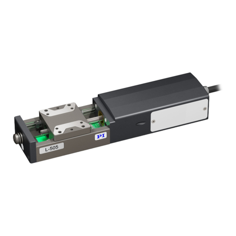
PI N-331 User manual

User Manual
PZ271E, valid for N-331
KSch, 1/18/2021
Physik Instrumente (PI) GmbH & Co. KG, Auf der Roemerstrasse 1, 76228 Karlsruhe, Germany Page 2 / 30
Phone +49 721 4846
Contents
About this Document 3
Symbols and Typographic Conventions............................................................................................................... 3
Figures ................................................................................................................................................................. 3
Other Applicable Documents .............................................................................................................................. 4
Downloading Manuals......................................................................................................................................... 4
Safety 4
Intended Use ....................................................................................................................................................... 4
Safety Precautions............................................................................................................................................... 5
Measures for Handling Vacuum-Compatible Products ....................................................................................... 6
Product Description 6
Model Overview .................................................................................................................................................. 6
Product View ....................................................................................................................................................... 7
Product Labeling.................................................................................................................................................. 8
Scope of Delivery............................................................................................................................................... 10
Accessories ........................................................................................................................................................ 10
Suitable Electronics ........................................................................................................................................... 10
Unpacking 10
Installation 11
General Notes on Installation............................................................................................................................ 11
Connecting the N-331 to a Protective Earth Conductor ................................................................................... 12
Integrating the N-331 ........................................................................................................................................ 13
Fixing the N-331 by Its Base Body .................................................................................................................................13
Fixing the N-331 by Its Runner .......................................................................................................................... 15
Connecting the N-331 to the Electronics .......................................................................................................... 16
Startup and Operation 18
General Notes on Startup and Operation ......................................................................................................... 18
Startup and Operation....................................................................................................................................... 19
Discharging the N-331 ....................................................................................................................................... 20
Maintenance 20
General Notes on Maintenance ........................................................................................................................ 20
Cleaning the N-331 ............................................................................................................................................ 21
Customer Service 21
Technical Data 22
Specifications..................................................................................................................................................... 22

User Manual
PZ271E, valid for N-331
KSch, 1/18/2021
Physik Instrumente (PI) GmbH & Co. KG, Auf der Roemerstrasse 1, 76228 Karlsruhe, Germany Page 3 / 30
Phone +49 721 4846
Maximum Ratings.............................................................................................................................................. 23
Ambient Conditions and Classifications ............................................................................................................ 24
Mechanical Load Capacity ................................................................................................................................. 24
Dimensions ........................................................................................................................................................ 26
N-331............................................................................................................................................................................. 26
N-331.1LU Vacuum Feedthrough.................................................................................................................................. 27
Pin Assignment .................................................................................................................................................. 28
N-331.xx ........................................................................................................................................................................ 28
N-331.xxU (vacuum compatible for 10-9 hPa) ............................................................................................................... 29
Old Equipment Disposal 30
About this Document
This document contains the information needed for the intended use of the N-331 (hereinafter
also referred to as “drive”).
Basic knowledge of servo systems, drive technologies and suitable safety measures is assumed.
Symbols and Typographic Conventions
CAUTION
Dangerous situation
If not avoided, the dangerous situation will result in minor injury.
Actions to take to avoid the situation.
NOTICE
Dangerous situation
If not avoided, the dangerous situation will result in damage to the equipment.
Actions to take to avoid the situation.
INFORMATION
Information for easier handling, tricks, tips, etc.
Figures
For better understandability, the colors, proportions and degree of detail in illustrations can
deviate from the actual circumstances. Photographic illustrations may also differ and must not
be seen as guaranteed properties.

User Manual
PZ271E, valid for N-331
KSch, 1/18/2021
Physik Instrumente (PI) GmbH & Co. KG, Auf der Roemerstrasse 1, 76228 Karlsruhe, Germany Page 4 / 30
Phone +49 721 4846
Other Applicable Documents
Product Document
E-712.xAN digital controller PZ195E user manual
PZ233E commands manual
Downloading Manuals
INFORMATION
If a manual is missing or problems occur with downloading:
Contact our customer service department (p. 21).
1. Open the website www.pi.ws.
2. Search the website for the product number (e.g., E-712).
3. Click the corresponding product to open the product detail page.
4. Click Downloads.
The manuals are shown under Documentation.
5. Click the desired manual and fill out the inquiry form.
The download link will then be sent to the email address entered.
Safety
Intended Use
The N-331 PICMAWalk drive is a laboratory device as defined by DIN EN 61010-1. It is intended
for indoor use and use in an environment that is free of dirt, oil, and lubricants.
Based on its design and realization the N-331 is intended for positioning, adjusting and shifting
loads on one axis at various velocities.
The N-331 is a drive for applications in automation or handling technology. The drive is not
intended for applications in areas in which a failure would present severe risks to human beings
or the environment. The drive is not intended for continuous operation.
Some models of the drive are equipped with optical, incremental sensors. Some models are
compatible for vacuum applications to 10 -9 hPa.
The intended use of the drive is only possible when installed and in conjunction with a suitable
electronics (p. 10). The electronics is not included in the scope of delivery of the drive.
The electronics must provide the required operating voltages. To ensure proper performance of
the servo-control system, the electronics must also be able to read out and process the signals
from the sensors.

User Manual
PZ271E, valid for N-331
KSch, 1/18/2021
Physik Instrumente (PI) GmbH & Co. KG, Auf der Roemerstrasse 1, 76228 Karlsruhe, Germany Page 5 / 30
Phone +49 721 4846
Safety Precautions
CAUTION
Dangerous voltage and residual charge on piezo actuators!
The drive contains piezo actuators. Temperature changes and compressive stresses can induce
charges in piezo actuators. After being disconnected from the electronics, piezo actuators can
also stay charged for several hours. Touching or short-circuiting the contacts in the drive’s
connector or of the connected vacuum feedthrough can lead to minor injuries. In addition, the
piezo actuators can be destroyed by an abrupt contraction.
Do not open the drive.
Discharge the piezo actuators of the drive before installation:
Connect the drive to the switched-off PI electronics, which is equipped with an internal
discharge resistor.
Do not pull out the connector from the electronics during operation.
Touching the contacts in the connector can lead to an electric shock (max. 130 V DC) and minor
injuries.
Do not touch the contacts in the connector or the connected vacuum feedthrough.
Secure the connector of the drive or of the adapter cable on the air side with screws
against being pulled out of the electronics.
CAUTION
Risk of crushing by moving parts!
There is a risk of minor injuries caused by crushing which can occur between the moving parts
of the drive and a stationary part or obstacle.
Keep your fingers away from areas where they can get caught by moving parts.
NOTICE
Destruction of the PICMAWalk drive by electric flashovers!
The drive contains piezo actuators. The use of the drive in environments that increase the
electrical conductivity can lead to the destruction of the piezo actuators by electric flashovers.
Electric flashovers can be caused by moisture, high humidity, liquids and conductive materials
such as metal dust. In addition, electric flashovers can also occur in certain air pressure ranges
due to the increased conductivity of the air.
Avoid operating the drive in environments that can increase the electric conductivity.
Only operate the drive within the permissible ambient conditions and classifications (see
p. 24).
For operation in vacuum below 0.1 hPa:
Do not operate the drive during evacuation and aeration.

User Manual
PZ271E, valid for N-331
KSch, 1/18/2021
Physik Instrumente (PI) GmbH & Co. KG, Auf der Roemerstrasse 1, 76228 Karlsruhe, Germany Page 6 / 30
Phone +49 721 4846
Measures for Handling Vacuum-Compatible Products
When handling the vacuum versions of the drive, attention must be paid to appropriate
cleanliness. At PI, all parts are cleaned before assembly. During assembly and measurement,
powder-free gloves are worn. Afterwards, the drive is cleaned once again by wiping and shrink-
wrapped twice in vacuum-compatible film.
Only touch the drive with powder-free gloves.
If necessary, wipe the drive clean after unpacking.
Product Description
Model Overview
Model Description
N-331.10 Piezoelectric walking drive PICMAWalk, 25 mm travel range, open loop,
50 N push/pull force
N-331.13 Piezoelectric walking drive PICMAWalk, 25 mm travel range, incremental sensor,
50 N push/pull force
N-331.20 Piezoelectric walking drive PICMAWalk, 50 mm travel range, open loop,
50 N push/pull force
N-331.23 Piezoelectric walking drive PICMAWalk, 50 mm travel range, incremental sensor,
50 N push/pull force
N-331.40 Piezoelectric walking drive PICMAWalk, 100 mm travel range, open loop,
50 N push/pull force
N-331.43 Piezoelectric walking drive PICMAWalk, 100 mm travel range, incremental
sensor, 50 N push/pull force
N-331.20U Piezoelectric walking drive PICMAWalk, 50 mm travel range, open loop,
50 N push/pull force, vacuum compatible to 10-9 hPa
N-331.24U Piezoelectric walking drive PICMAWalk, 50 mm travel range, incremental sensor,
50 N push/pull force, vacuum compatible to 10-9 hPa

User Manual
PZ271E, valid for N-331
KSch, 1/18/2021
Physik Instrumente (PI) GmbH & Co. KG, Auf der Roemerstrasse 1, 76228 Karlsruhe, Germany Page 7 / 30
Phone +49 721 4846
Product View
Figure 1: Example view of a drive without sensor (N-331.x0)
1Cable exit
2Base body
3Runner
4Ceramic rail (side view)
5Cover
X: The arrow indicates the positive direction of motion.
Figure 2: Example view of a drive with integrated sensor (N-331.x3)
1Ceramic rail (top view)
2Ruler of linear encoder (do not touch)

User Manual
PZ271E, valid for N-331
KSch, 1/18/2021
Physik Instrumente (PI) GmbH & Co. KG, Auf der Roemerstrasse 1, 76228 Karlsruhe, Germany Page 8 / 30
Phone +49 721 4846
Figure 3: Position of the protective earth connection
1Position of symbol for the protective earth conductor
2M4 mounting hole
Product Labeling
Figure 4: Position of the product labeling on the drive
Labeling Description
N-331.20 Product name (example), the characters following the period refer to the
model
116010244
Serial number (example), individual for each drive
Meaning of the places (counting from left):
1 = internal information
2 and 3 = year of manufacture
4 to 9 = consecutive numbers
PICMAWalk Brand name

User Manual
PZ271E, valid for N-331
KSch, 1/18/2021
Physik Instrumente (PI) GmbH & Co. KG, Auf der Roemerstrasse 1, 76228 Karlsruhe, Germany Page 9 / 30
Phone +49 721 4846
Labeling Description
Manufacturer's logo
Country of origin:
Germany Country of origin
Warning sign "Observe manual!"
Old equipment disposal (p. 30)
CE conformity mark
WWW.PI.WS Manufacturer's address (website)
Symbol for the protective earth conductor, marks the drive’s protective
earth connection (p. 12)
Labeling of the Sub-D 37 (m) connector
Figure 5: Sub-D 37 (m) connector of the N-331.xx models or of the N-331.02 adapter cable on the air side
Warning sign "Residual Voltage": Notice of risk of electric shock (p. 5)

User Manual
PZ271E, valid for N-331
KSch, 1/18/2021
Physik Instrumente (PI) GmbH & Co. KG, Auf der Roemerstrasse 1, 76228 Karlsruhe, Germany Page 10 / 30
Phone +49 721 4846
Scope of Delivery
Item ID Components
N-331 PICMAWalk drive according to order (p. 6)
000036450 M4 screw set for protective earth, consisting of:
1 M4x8 flat-head screw with cross recess, ISO 7045
2 safety washers
2 flat washers
PZ271E User manual (this document) in printed form
Accessories
Only for N-331.xxU model (suitable for use in a vacuum to 10-9 hPa)
Item ID Components
N-331.02 Adapter cable, LEMO 19-pin (f) to D-Sub 37 (m), 2 m
N-331.1LU Vacuum feedthrough (drive and sensor signals), LEMO 19-pin (m/m),
DN40CF
Suitable Electronics
Electronics Description
E-712.1AN Digital controller for PICMAWalk walking drive, 1 channel
E-712.2AN Digital controller for PICMAWalk walking drive, 2 channels
E-712.3AN Digital controller for PICMAWalk walking drive, 3 channels
PC software is included in the scope of delivery of the electronics from PI. The operation of the
electronics is described in the corresponding user manuals.
Unpacking
INFORMATION
When handling the vacuum version of the drive, attention must be paid to appropriate
cleanliness. At PI, all parts are cleaned before assembly. Powder-free gloves are worn during
assembly and measuring. In addition, the drive is wipe cleaned afterwards and then shrink-
wrapped twice in vacuum-compatible film.
Touch the drive only with powder-free gloves.
If necessary, wipe the drive clean after unpacking.

User Manual
PZ271E, valid for N-331
KSch, 1/18/2021
Physik Instrumente (PI) GmbH & Co. KG, Auf der Roemerstrasse 1, 76228 Karlsruhe, Germany Page 11 / 30
Phone +49 721 4846
1. Unpack the drive with care.
2. Compare the contents with the items listed in the contract and the packing list.
3. Inspect the contents for signs of damage. If parts are missing or you notice signs of
damage, contact PI immediately.
4. Keep all packaging materials in case the components need to be returned.
Installation
General Notes on Installation
NOTICE
Damage due to mechanical actions!
The encoder scale is scratch-sensitive and can be damaged by mechanical actions, e.g. from
pointed objects.
Handle the encoder scale with great care.
Do not touch the encoder scale and the ceramic rail.
Protect the encoder scale and the ceramic rail from dirt and lubricants.
Figure 6: Ruler (1) of the linear encoder and ceramic rail (2) of the drive. The ruler is accessible when the
runner is extended.
NOTICE
Malfunction due to soiling!
Any type of soiling, e.g. dust, oil, grease or condensation, will render the drive inoperable.
Keep the drive free from lubricants, dirt and condensation.
Avoid touching the ceramic rail of the drive and the ruler of the linear encoder.

User Manual
PZ271E, valid for N-331
KSch, 1/18/2021
Physik Instrumente (PI) GmbH & Co. KG, Auf der Roemerstrasse 1, 76228 Karlsruhe, Germany Page 12 / 30
Phone +49 721 4846
NOTICE
Heating up of the drive during operation!
The heat produced during operation of the drive can affect your application.
Install the drive so that the application is not affected by the dissipated heat.
Ensure sufficient ventilation at the place of installation.
Make sure that the complete drive is underneath in contact with the surface on which the
drive is fixed.
NOTICE
Damage due to collisions!
Collisions can damage the drive, the load to be moved, and the surroundings.
Make sure that no collisions are possible between the drive, the load to be moved, and the
surroundings in the motion range of the drive.
Do not place any objects in areas where they can be caught by moving parts.
INFORMATION
For the positive direction of motion of the runner, see "Product View" (p. 7).
Connecting the N-331 to a Protective Earth Conductor
INFORMATION
Pay attention to the applicable standards for mounting the protective earth conductor.
The drive features a separate protective earth connection, see “Dimensions” on p. 24.
Figure 7: Example of a protective earth connection
Tools and accessories
Suitable protective earth conductor: Cross-sectional area of the cable ≥0.75 mm2
Suitable screwdriver
M4 screw for connecting the protective earth conductor

User Manual
PZ271E, valid for N-331
KSch, 1/18/2021
Physik Instrumente (PI) GmbH & Co. KG, Auf der Roemerstrasse 1, 76228 Karlsruhe, Germany Page 13 / 30
Phone +49 721 4846
Connecting the protective earth conductor to the separate protective earth
connection
Figure 8: Recommended mounting of the protective earth conductor (profile view)
1Base body of the drive
2Flat washer
3Safety washer
4Screw
5Cable lug
6Protective earth conductor
1. If necessary, attach a suitable cable lug to the protective earth conductor.
2. Use the M4 screw (together with the washers and self-locking washers) to affix the cable
lug of the protective earth conductor to the protective earth connection of the drive as
shown in the profile view.
3. Tighten the M4 screw with a torque of 1.2 Nm to 1.5 Nm.
4. Make sure that the contact resistance at all connection points relevant for connecting the
protective earth conductor is <0.1 Ω at 25 A.
Integrating the N-331
The mounting holes in the underneath of the base body and at both ends of the runner make it
possible to integrate the drive into an assembly.
Fixing the N-331 by Its Base Body
NOTICE
Warping of the drive due to mounting on uneven surfaces and lateral forces!
Mounting the drive onto an uneven surface can warp the drive. Lateral forces on the runner
can warp the runner. Warping reduces the specifications of the drive.
Mount the drive onto an even surface. The recommended evenness of the surface
is ≤20 µm.
For applications with large temperature changes:
Only mount the drive onto surfaces that have the same or similar thermal expansion
properties as the drive.
Runner and movable part of the assembly, where the drive is to be integrated in, have to
be parallel.

User Manual
PZ271E, valid for N-331
KSch, 1/18/2021
Physik Instrumente (PI) GmbH & Co. KG, Auf der Roemerstrasse 1, 76228 Karlsruhe, Germany Page 14 / 30
Phone +49 721 4846
Figure 9: Mounting holes on the bottom of the drive.
See "Dimensions" (p. 24) for the exact location of the mounting holes.
Requirements
You have read and understood the safety precautions (p. 5) and the general notes on
installation (p. 11).
The drive is not connected to the electronics.
You have provided a suitable surface:
−Three M4 holes are present.
−The evenness of the surface is ≤20 µm.
−For applications with large temperature changes: The surface should have the same
thermal expansion properties as the drive.
You have accounted for the space required to route cables without bending and according
to regulations.
Tools and accessories
3 M4 screws of suitable length (p. 24)
Fixing the N-331 by its base body
1. Align the drive on the surface so that the M4 holes in the base body and the surface
overlap.
2. Insert the three screws through the holes in the surface into the drive’s base body
from below.
3. Tighten the three screws.
−Maximum screw-in depth: 7 mm
−Maximum torque: 2.6 Nm
4. Check that the drive fits without backlash.

User Manual
PZ271E, valid for N-331
KSch, 1/18/2021
Physik Instrumente (PI) GmbH & Co. KG, Auf der Roemerstrasse 1, 76228 Karlsruhe, Germany Page 15 / 30
Phone +49 721 4846
Fixing the N-331 by Its Runner
Figure 10: Examples for decoupling elements; Left: For lateral fixing, right: For axial fixing
NOTICE
Mechanical overload due to high torques and high forces!
High torques when fixing the runner to an assembly can overload the drive’s runner.
Mechanical overload can damage the drive.
Hold the runner firmly to prevent it from moving when tightening the screws.
Pay attention to the maximum permissible forces according to the maximum values for
torque and forces (p. 24).
Avoid tilting torques on the runner.
The coupling between runner and assembly must be very stiff in the runner’s motion
direction, here along X axis, but flexible in Y and Z axes.
See Figure 10 for a drive with two examples for decoupling elements: these allow a stiff
coupling and prevent force or torque on the runner when the runner is fixed to the
assembly.
Make sure that displacement of the runner in Y and Z directions does not occur.
The runner can be fixed to an assembly on both sides of the runner.
Figure 11: Lateral views of drive: Fixing the runner with M4 screws
1M4 inner thread in the runner, at side with cable exit
2M4 inner thread in the runner, at the opposite side

User Manual
PZ271E, valid for N-331
KSch, 1/18/2021
Physik Instrumente (PI) GmbH & Co. KG, Auf der Roemerstrasse 1, 76228 Karlsruhe, Germany Page 16 / 30
Phone +49 721 4846
Tools and accessories
Optional:
−Suitable decoupling element
−Suitable screws to fix the decoupling element to the assembly
−Suitable screwdriver
M4 screw of suitable length (p. 26)
Screwdriver for M4 screw
Requirements
You have read and understood the safety precautions (p. 5) and the general notes on
installation (p. 11).
The drive is not connected to the electronics.
You have fixed the drive properly.
The distance between the center of gravity of the load and the center of the hole in the
runner is as small as possible in all directions.
Fixing the N-331 by its runner
1. Choose one side of the runner where to fix it to the assembly.
2. Optional: Fix a suitable decoupling element to the runner holding the runner firmly to
avoid torque on it and to hold it in place.
Pay attention to a maximum torque, see p. 24 and Figure 13 on p. 25.
3. Optional: Fix the decoupling element to the assembly with suitable screws.
Pay attention to a maximum torque, see p. 24 and Figure 13 on p. 25.
4. If the runner is to be fixed to the assembly directly use the M4 screw. Hold the runner
firmly to avoid torque on it.
Pay attention to a maximum torque of 0.2 Nm.
5. Optional: Fix the other side of the runner to the assembly repeating steps 2 to 4.
Connecting the N-331 to the Electronics
Requirements
You have read and understood the safety precautions (p. 5) and the general notes on
installation (p. 11).
You have installed the electronics (p. 10).
You have read and understood the user manual of the electronics.
The electronics are switched off.
Tools and accessories
For N-331.xxU, i.e. for operation in a vacuum:

User Manual
PZ271E, valid for N-331
KSch, 1/18/2021
Physik Instrumente (PI) GmbH & Co. KG, Auf der Roemerstrasse 1, 76228 Karlsruhe, Germany Page 17 / 30
Phone +49 721 4846
−N-331.1LU vacuum feedthrough (suitable for use in a vacuum to 10-9 hPa), available
as optional accessory (p. 10)
−N-331.02 air-side cable, available as optional accessory (p. 10)
−Suitable tools for installing the vacuum feedthrough
Figure 12: Connection diagrams: Top: for N-331.xx at atmospheric pressure, bottom: for N-331.xxU at
vacuum to 10-9 hPa
1. For N-331.xxU: Install the vacuum feedthrough:
a) Obtain the dimensions from the corresponding dimensional drawing (p. 27).
b) Make sure that the vacuum feedthrough is oriented correctly, see p. 27.
c) Make a suitable opening in the vacuum chamber.
d) Install the vacuum feedthrough.
2. Connect the drive and the electronics to each other as shown in the connection diagram
above.
3. Take suitable measures to secure the connections against accidental disconnection.

User Manual
PZ271E, valid for N-331
KSch, 1/18/2021
Physik Instrumente (PI) GmbH & Co. KG, Auf der Roemerstrasse 1, 76228 Karlsruhe, Germany Page 18 / 30
Phone +49 721 4846
Startup and Operation
General Notes on Startup and Operation
CAUTION
Risk of electric shock if the protective earth conductor is not connected!
If a protective earth conductor is not or not properly connected, dangerous touch voltages can
occur and there is a risk of electric shock. In the case of malfunction or failure of the system,
touching the drive or the contacts of the connected vacuum feedthrough can result in minor
injuries.
Connect the drive to a protective earth conductor (p. 12) before start-up.
Do not remove the protective earth conductor during operation.
If the protective earth conductor has to be temporarily removed (e.g., for modifications),
reconnect the drive to the protective earth conductor before starting it up again.
NOTICE
Destruction of the PICMAWalk drive by electric flashovers!
The drive contains piezo actuators. The use of the drive in environments that increase the
electrical conductivity can lead to the destruction of the piezo actuators by electric flashovers.
Electric flashovers can be caused by moisture, high humidity, liquids and conductive materials
such as metal dust. In addition, electric flashovers can also occur in certain air pressure ranges
due to the increased conductivity of the air.
Avoid operating the drive in environments that can increase the electric conductivity.
Only operate the drive within the permissible ambient conditions and classifications (see
p. 24).
For operation in vacuum below 0.1 hPa:
Do not operate the drive during evacuation and aeration.
NOTICE
Destruction of the piezo actuator by continuously high voltage!
The constant application of high voltage to piezo actuators can lead to leakage currents and
flashovers that destroy the ceramic.
If the drive is not used, but the electronics is to remain switched on to ensure temperature
stability:
In closed-loop operation:
1. Switch the servo mode off on the electronics (open-loop operation).
2. Set the piezo voltage to 0 V on the electronics.
In open-loop operation:
Set the piezo voltage to 0 V on the electronics.

User Manual
PZ271E, valid for N-331
KSch, 1/18/2021
Physik Instrumente (PI) GmbH & Co. KG, Auf der Roemerstrasse 1, 76228 Karlsruhe, Germany Page 19 / 30
Phone +49 721 4846
NOTICE
Operating voltage too high or incorrectly connected!
Operating voltages that are too high or incorrectly connected can cause damage to the drive.
Only operate the drive with a electronics from PI.
Do not exceed the operating voltage range (p. 23) for which the drive is specified.
Only operate the drive when the operating voltage is properly connected; see "Pin
Assignment" (p. 28).
NOTICE
Uncontrolled oscillation!
Oscillations can cause irreparable damage to the drive. Oscillations are indicated by a humming
and can result from the following causes:
A change in the load and/or dynamics requires the servo-control parameters to be
adjusted.
The drive is operated near its resonant frequency.
If you notice oscillations:
In closed-loop operation, immediately switch off the servo mode.
In open-loop operation, immediately stop the drive.
NOTICE
Damage due to travel to the hard stop!
Repeated travel to the hard stop can cause damage and considerable wear to the mechanics.
Stop the motion immediately if a electronics malfunction occurs.
Set the control signal so that the moving part does not try to continue moving at the end of
the travel range.
INFORMATION
In a vacuum, there is no heat dissipation via convection.
We recommend to operate the vacuum version of the drive with a maximum duty cycle of
30 % with a maximum duration of motion of 10 sec.
Select an underlying surface for fixing the N-331.xxU that has high thermal conductivity.
Make sure that the entire lower surface of the N-331.xxU contacts the underlying surface
that it is fixed to.
Startup and Operation
Requirements
You have read and understood the safety precautions (p. 5) and the general notes on
startup and operation (p. 18).
You have read and understood the user manual of the electronics.

User Manual
PZ271E, valid for N-331
KSch, 1/18/2021
Physik Instrumente (PI) GmbH & Co. KG, Auf der Roemerstrasse 1, 76228 Karlsruhe, Germany Page 20 / 30
Phone +49 721 4846
You have properly installed the drive (p. 11).
The electronics and the required PC software have been installed. All connections with the
electronics have been established (see user manual of the electronics).
Startup and operation
For startup and operation of the drive, follow the instructions in the manual of the
electronics used.
Discharging the N-331
The drive must be discharged in the following cases:
Before installation
If the drive is not used but the electronics remains switched on to ensure temperature
stability
Before demounting (e.g., before cleaning and transporting the drive and for
modifications)
The drive is discharged through the internal discharge resistor of the electronics from PI.
Discharging an N-331 that is connected to the electronics
In closed-loop operation:
1. Switch off the servo mode on the electronics.
2. Set the piezo voltage to 0 V on the electronics.
In open-loop operation:
Set the piezo voltage to 0 V on the electronics.
Discharging an N-331 that is not connected to the electronics
Connect the drive to the switched-off electronics from PI.
Maintenance
General Notes on Maintenance
NOTICE
Misalignment from loosening screws!
The drive is maintenance-free and achieves its positioning accuracy as a result of the optimum
alignment of mechanical components and piezo actuators. Loosened screws cause a loss in
positioning accuracy.
Only loosen screws according to the instructions in this document.
Do not open the drive.
Table of contents
Other PI Laboratory Equipment manuals
Popular Laboratory Equipment manuals by other brands

Hanil
Hanil Ultra 5.0 quick guide

Lafayette Instrument
Lafayette Instrument Flicker Fusion 12021A User instructions

Hettich
Hettich ROTINA 420 R Repair instructions

WPI
WPI LWCC-M-10 instruction manual

Metrohm
Metrohm 930 Compact IC Flex manual

Atie Medical Industries
Atie Medical Industries PS-140 user manual