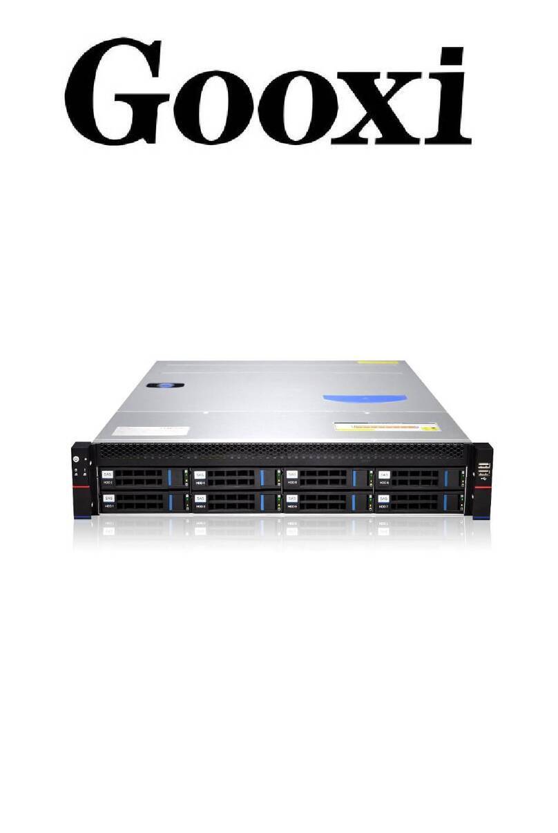
Gooxi ASR4105G-D12R User manual

ASR4105G-D12R
4U Rackmount Server
User Manual
Document version: 01
Release date: 2023/05/18
Shenzhen Gooxi Information security Co., Ltd.

1
Statement
Copyright Statement
© Shenzhen Gooxi Information Security Co., Ltd. All rights reserved.
This user manual, including but not limited to all information contained herein, is protected by
copyright law. Without the permission of Shenzhen Gooxi Information Security Co., Ltd.
(hereinafter referred to as "Gooxi"), no one may engage in any behavior such as imitation,
copying, excerpting, forwarding, or other forms of utilization.
Disclaimer
Gooxi provides this user manual "as is" and to the extent permitted by law, makes no express or
implied warranties or guarantees, including but not limited to merchantability, fitness for a
particular purpose, non-infringement of any rights of others, and any warranties or guarantees
regarding the use or inability to use this user manual. Gooxi also does not provide any warranties
or guarantees regarding the accuracy or reliability of any information obtained using this user
manual.
Due to product version upgrades or other reasons, the content of this user manual may be
periodically updated. Unless otherwise specified, this user manual is provided solely as a usage
guide, and users shall bear all risks associated with the use of this user manual.
Trademark Statement
Gooxi® is a trademark of Shenzhen Gooxi Information Security Co., Ltd.
Microsoft® and Windows is a trademark of the Microsoft group of companies.
Linux® is a registered trademark of Linus Torvalds.
Aspeed® is a trademark of ASPEED Technology Inc.
Ownership of other trademarks belongs to their respective owners.

2
Foreword
This manual is the product technical manual for the AS401 Whitley platform 4U model servers.
It primarily provides an introduction and explanation of the product's appearance, structure,
hardware installation, and basic configuration.
Please note that this manual is intended for reference and research purposes for professional
technical personnel. The installation and maintenance of this product should only be performed
by experienced technical personnel.
Modification Record
Manual version
Release date
Modification instructions
V 0.1
2023-05-18
First release

3
Contents
Statement ................................................................................................................................. 1
Foreword ................................................................................................................................. 2
.............................................................................................................. 4
1.1 Product Overview ........................................................................................................4
1.2 Product Structure .........................................................................................................5
1.3 Logical Structure ......................................................................................................... 5
1.4 Product Specifications ................................................................................................. 7
............................................................................................................ 8
2.1 Front Panel ..................................................................................................................8
2.1.1 Appearance ....................................................................................................... 8
2.1.2 Indicator lights and buttons ................................................................................ 8
2.1.3 Interface ........................................................................................................... 9
2.2 Rear Panel .................................................................................................................10
2.2.1 Appearance ..................................................................................................... 10
2.2.2 Indicator lights and buttons .............................................................................. 11
2.3 Processor .................................................................................................................. 12
2.4 Memory _ ................................................................................................................. 13
2.4.1 Memory slot location .......................................................................................13
2.4.2 Memory compatibility information ................................................................... 13
2.5 Storage _ ...................................................................................................................14
2.5.1 Hard drive configuration .................................................................................. 14
2.5.2 Hard drive serial number ..................................................................................14
2.5.3 hard drive status indicator ................................................................................ 14
2.6 Power Supply ............................................................................................................ 15
2.7 Fans _ ....................................................................................................................... 15
2.8 I/O Expansion ........................................................................................................... 16
2.8.1 PCIe slot location ............................................................................................ 16
2.8.2 PCIe slot description ........................................................................................16
2.8.3 PCIE expansion module ...................................................................................17
2.9 PCBA _ .................................................................................................................... 17
2.9.1 Motherboard ................................................................................................... 17
2.9.2 Hard drive backplane .......................................................................................19
........................................................................................................ 21
3.1 Installation of the Chassis Top Cover ..........................................................................21
3.2 Accessories Installation ..............................................................................................21
3. 2.1 CPU installation ............................................................................................. 21
3.2.2 Heatsink installation. ....................................................................................... 23
3.2.3 Memory installation .........................................................................................24
3.2.4 Server slide rail installation .............................................................................. 25
....................................................................................................27
4.1 Initial Configuration .................................................................................................. 27
4.1.1 Power on and start ........................................................................................... 27
4.1.2 Initial data .......................................................................................................27
4.1.3 BIOS Configuration .........................................................................................28
4.1.4 BMC Configuration .........................................................................................28
............................................................................................................................ 32
4
1.1 Product Overview
The ASR4105G-D12R dual-socket server is a new-generation 4U rack-mounted server
offered by Gooxi to meet the demands of various applications, including the internet, IDC
(Internet Data Center), cloud computing, enterprise markets, and telecom services. It is
suitable for IT core operations, cloud computing virtualization, high-performance computing,
distributed storage, big data processing, enterprise or telecom service applications, and other
complex workloads. This server features advantages such as low power consumption, strong
scalability, high reliability, easy management, and straightforward deployment.
Product main features:
Supports 2 AMD For EPYC 7003/7002/7001 series CPUs, the maximum TDP is 240W.
Supports 10 PCIe high-speed expansion slots, providing rich expansion performance.
Supports 5 full-height and double-width high-performance GPU cards to meet the needs
of high computing power.
Supports 16 DDR4 memory slots.
Server Physical Image
Front View (Figure 1-1)

5
Rear View (Figure 1-2)
1.2 Product Structure
ASR4105G-D12R server components, as shown in the following image:
Structure diagram 1-3
No.
Name
No.
Name
1
Front hard drive (optional)
8
Fan bracket
2
Front hard drive module
9
Cover
3
Front panel
10
Power supply enclosure
4
Fan module
11
Rear 2.5-inch hard drive module
5
Memory stick
12
Power supply
6
CPU & Heat sink
13
Rear window
7
PCIE expansion slot
14
GPU card (optional)
Table 1-1
1.3 Logical Structure
The motherboard logic is as shown in the following diagram:

6
DDR 4 DIMM0
DDR 4 DIMM0
DDR 4 DIMM0
DDR 4 DIMM0
DDR 4 DIMM0
DDR 4 DIMM0
DDR 4 DIMM0
DDR 4 DIMM0
SYS DEBUG( Header )
PCIE4.0 x16 Slot *2
PCIE 4.0 x 8 Slots * 2
TPM Header
MiniSAS HD * 2
M.2 _ _
LPC
RS
232( Heade
r) PHY _
D - sub ( Rear ) & Header
( Front )
AST 2500
SPI
F RU ROM
DDR4
B M C DEBUG ( Header )
CPLD
Motherboard logic block diagram 1-4
2 SP3 Sockets, supporting 2 AMD EPYC 7003/7002/7001 series processors.
Supports 8 DDR4 channels, each channel supports 1 DIMM, and supports a total of 16DIMM DDR4
memory.
The motherboard features 10 PCIe slots, including: 6 PCIe x8 (x16 slot) and 4 PCIe x16.
The motherboard provides 1 M.2 Key M SSD slot, supporting only 2280 size and PCIe X4 signal (not
compatible with SATA).
The motherboard integrates 2 Gigabit Ethernet ports, using I350-AM2 chip.
The BMC chip in the motherboard adopts the AST2500 control chip of ASPEED Company, which is
used for IPMI remote management, VGA Output port, dedicated Gigabit RJ45 management network
port.
Note: 1. There are PCIe3.0 and PCIe4.0 versions for the motherboard.
2. Various firmware support is needed to accommodate AMD EPYC 7003/7002/7001 series processors.
CH_A DDR4 DIMM0
CH_B DDR4 DIMM0
CH_C DDR4 DIMM0
CH_D DDR4 DIMM0
CH_E DDR4 DIMM0
CH_F DDR4 DIMM0
CH_G DDR4 DIMM0
CH_H DDR4 DIMM0
TPM Header
I2C
USB2.0
PCIE2.0 x1
PCIE4.0 x8 Slot *4
PCIE4.0 x16 Slot
PCIE4.0 x16 Slot
x16 xGMI
x16 xGMI
x16 xGMI
x16 xGMI
x2 WAFL
PCIE4.0x8 x2
PCIE4.0x4 x2
PCIE4.0x4 x1
CPU0
CPU1
FAN*8
IPMB(Header)
CH_A
CH_B
CH_C
CH_D
CH_E
CH_F
CH_G
CH_H
USB3.0 *2(Rear)
Vertical USB3.0
PCIE4.0 x8x4
PCIE4.0 x16
PCIE4.0 x16
G2
G0
G3
G1
USB3.0 *2(Front)
G0
G2
G1
G3
PCIE2.0 x1
USB3.0 X3
UART
PWM
SMBUS
I350-AM2 PCIE2.0 X2
BMC BIOS
PCIE4.0x16 x2
IPMI LAN
μPD720201
RJ45*2
JTAG
MUX
BIOS
SW
SMBUS
RGMII
COM
COM
NCSI
VGA
SPI
SPI

7
1.4 Product Specifications
System Model
ASR4105G-D12R
ASR4105G-D12RE
Chassis
4 U rack-mount chassis (695*433*176.5mm)
Motherboard
G2DERO-B
CPU
Supports 2 AMD EPYC 7003/7002/7001 series processors
Memory *
16 DDR4 slots, supports 2133/2400/2666/2933MHz DDR4 RDIMM / LRDIM
memory, compatible with a single capacity of 16GB, 32GB, 64GB, 128GB,
the whole machine supports a maximum of 4TB memory capacity.
Hard Drive
The front supports 12*3.5 or 2.5-inch
hard drives (directly connected to the
backplane)
The front supports 12*3.5 or 2.5-inch
hard drives (expansion backplane)
The rear supports expansion of 2*2.5-inch hard drives
Network Function
Supports 2 RJ45 Gigabit network ports
Management
Interface
1 RJ45 IPM I management network port
Display Function
Expanded with 1 standard VGA interface using Aspeed AST2500.
M.2
Supports 1 M.2 interface (only support 2280 size NVMe SSD)
USB _
2 front USB3.0 ports, 1built-in USB3.0, USB3.0 port at the rear
Expansion Slot
Supports up to 10 PCIE expansion slots
Power Supply
The system supports 550W, 800W, 1200W, 1300W, 1600W hot -swappable
redundant power supplies
System Fan
The system supports four 8038 temperature-controlled fans
System Size
695*433. 4*87.6mm (L*W*H)
Supported OS
RedHat RHEL 6.4 and above
CentOS 6.4 or above
SUSE SLES 12 SP 5, SLES 15SP2 and later versions
Ubuntu Server / Desktop 14.04 or above
Microsoft Windows server 2016/2019 etc.
Operating
Temperature &
Humidity
Temperature 5℃~35℃; Humidity: 35%~80% non- condensing
Storage
Temperature &
Humidity
Short time (≤72 H): temperature -40℃~70℃/humidity 20%~90%
non-condensing (including packaging)
Long time (>72 H): temperature 20 ℃~28℃/humidity 30%~70% non-
condensing (including packaging)
Certificates
CCC、ROHS
Table 1-2

8
2.1 Front Panel
2.1.1 Appearance
Front view
Figure 2-1
No.
Name
No.
Name
1
Front switch panel
2
3. 5-inch hard drive
3
USB 3.0 interface
-
-
table 2-1
2.1.2 Indicator lights and buttons
Figure 2-2
No.
Indicator light /button
No.
Indicator light /button
1
Power switch button/indicator
4
System alarm Indicator
2
Reset server button
5
Network port 1 connection
status indicator
3
Hard drive indicator
6
Network port 2 connection
status indicator
LED status description
logo
Indicator light
/button
status description

9
power indicator
Description of the power indicator light:
Green (steady on): Indicates that the device has been
powered on normally.
Green (blinking): Indicates that the device is in standby.
Green off: Indicates that the device is not powered on.
Power button description:
Short press this button in the power-on state, and the OS
will shut down normally.
Press and hold the button for 6 seconds in the power-
on state to force the server to Power off.
Press the button shortly in the power-on state to start the
machine.
Reset server
button
Press to restart the server
Hard drive
indicator
Blinking green light: The hard drive is operating
normally
System alarm
indicator
System warning indicator. Including system alarm, fan
alarm, power Source alarm, etc., you can view it
through the IPMI management software
Network port
connection
status indicator
Corresponds to the Ethernet port indicator of the
network card.
Green (steady on): Indicates that the network port is
connected normally.
Off: Indicates that the network port is not in use or
faulty.
Note: Corresponds to the two 1 GE network ports on the
motherboard.
Table 2-2
2.1.3 Interface
Interface location
Figure 2-3
Interface Description

10
Name
Type
Quantity
Description
USB interface
USB 3.0
2
For accessing USB devices
Table 2-3
2.2 Rear Panel
2.2.1 Appearance
Rear panel appearance interface
Figure 2-4
1
power module
6
USB 3.0 interface _
2
Power module AC port
7
RJ45 Gigabit network port
3
2.5-inch hard drive module
(optional)
8
COM port, VGA port
4
BMC Reset button
9
UID button
5
Management network port
1 0
PCIe expansion slot
Table 2-4
Rear panel interface description
VGA interface
DB15 _
1
Used to connect a display terminal, such as a
monitor or KVM.
Management network
port
GE BASE-T
1
Provides an external 1000Mbit/s Ethernet port.
This interface allows for the management of
this server.
USB interface
USB 3.0
2
Provides an external USB interface for
connecting USB devices.
Note: When using external USB devices, please
ensure that the USB device is in good
condition, as it may otherwise lead to server
malfunctions.
RJ45 Gigabit network
port
GE BASE-T
2
Server business network port.

11
Power module AC
port
/
1 or 2
You can choose the number of power supplies
according to your actual needs, but make sure
that the rated power of the power supply is
greater than the rated power of the whole
machine rate.
COM port
DB9
1
serial communication port
Table 2-5
2.2.2 Indicator lights and buttons
Rear panel indicators
Figure 2-5
No.
Name
No.
Name
1
Power module indicator
2
BMC reset button
3
Connection status indicator
4
Data transmission status
indicator
5
Connection status indicator
6
Data transmission status
indicator
7
UID button
-
-
Table 2-6
Description of Power Module Indicators
Indicator Light/ Button
Status Description
Power module
indicator
Green (steady on): Indicates that the input and output are
normal.
Orange (steady on): Indicates AC power cable unplugged or
power module missing, and only one parallel power module
has AC input. Power module failure results in output
shutdown, such as OVP, OCP, fan failure, etc.
Green (1Hz/blink): Indicates normal input. Voltage is low
(less than 12V), or the power supply is in intelligent power-
on state.
Green (2Hz/blink): Indicates Firmware is in the process of
online upgrade.
Orange (1Hz/blink): Indicates continuous operation power
supply warning events, high temperature, high power, high
current.
Off: Indicates no AC power input.

12
Connection Status
Indicator
Steady green: indicates Gigabit Link.
Steady orange: indicates 100M link .
Off: 10M Link .
Data transmission status
indicator
Yellow (blinking): Indicates that data is being transmitted.
Off: Indicates no data transmission.
UID button
UID button control on server
BMC reset button
BMC button control on the server
Table 2-7
2.3 Processor
Supports 2 AMD EPYC 7003/7002//7001 series CPUs.
When configuring 1 processor, it needs to be installed in CPU 0 position.
The processors configured in the same server must have the same model.
For specific optional system options, please consult Gooxi sales.
The position of the processor is as shown in the figure below:
Figure 2-6

13
2.4 Memory _
2.4.1 Memory slot location
The motherboard supports 8 DDR4 channels, each channel supports 1 DIMM, and supports a
total of 16 DDR4 slots (When using a single memory module, it is recommended to insert it
into the slot indicated by the red box in the diagram below).
memory slot location
Figure 2-7
2.4.2 Memory compatibility information
The motherboard supports DDR4 RDIMM / LRDIMM server memory, and the memory
frequency supports 2133/2400/2666/2933MHz.
Note:
The same server must use the same type of DDR4 memory, and all memory must
run at the same speed, The velocity value is the lowest of the following:
Memory speed supported by specific CPU. The maximum operating speed for
specific memory configurations.
DDR4 memory of different types (RDIMM, LRDIMM) and different
specifications (capacity, bit width, rank, height, etc.) does not support mixed usage.
Different models of CPUs support different maximum memory capacities. (See
AMD's Memory Population Guidelines)

14
2.5 Storage _
2.5.1 Hard drive configuration
Configuration
Maximum Number of
Front Hard Drives (pcs)
Maximum Number of Rear Hard
Drives (pcs)
Description
1 2x3.5-inch
hard drives.
Direct
configuration
Supports twelve 3.5" or
2.5 " SAS/SATA HDD
– Onboard direct
connection only
supports 8 SATA
hard drive
2 *2.5-inch SAS/SATA hard
drive
Support
requires the
optional SAS
pass-through
card or RAID
card.
1 2x3.5-inch
hard drives.
EXP
configuration
Supports twelve 3.5"
or 2.5-inch
SAS/SATA hard
drive
2 *2.5-inch SAS/SATA hard
drive
Support
requires the
optional SAS
pass-through
card or RAID
card.
Note: The 3.5-inch hard drive cage is compatible with 2.5-inch hard drives
Table 2-8
2.5.2 Hard drive serial number
12 x3.5/2.5-inch hard drive configuration
Figure 2-8
2.5.3 hard drive status indicator
Figure 2-9
Hard drive status indicator description
Function
Act LED
Fault LED
Status LED
Hard drive in
place
always on
OFF
OFF
hard drive activity
Blinking 4Hz/sec
OFF
OFF
Hard drive
positioning
always on
Blinking 4Hz/sec
OFF

15
Hard drive error
always on
OFF
always on
RAID rebuild
always on
OFF
Blinking 1Hz/second
Table 2-9
2.6 Power Supply
Supports 1 or 2 power modules.
Supports AC or DC power modules.
Supports hot swap.
When configuring 2 power modules, it supports 1+1 redundant backup.
For power modules configured on the same server, the power module models must be
the same.
For specific optional system options, please consult Gooxi sales.
The location of the power supply is shown in the figure below:
Figure 2-10
2.7 Fans _
Supports 8 fan modules.
Supports hot swap.
Supports single fan failure.
Supports variable fan speed.
Fan modules configured on the same server must have the same model.
The location of the fan is shown in the figure below:

16
Figure 2-11
2.8 I/O Expansion
2.8.1 PCIe slot location
Figure 2-12
The PCIe expansion slots are Slot 1, 2, 3, 4, 5, 6, 7, 8, 9, and 10.
2.8.2 PCIe slot description
When CPU1 is not in place, its corresponding PCIe slots are not available.
PCIe Slot
Subordinate CPU
PCIe Standard
Bus Bandwidth
Slot Size
Slot 1
CPU 1
PCIe 3.0 or 4.0
X8
x16 slots
Slot 2
CPU 1
PCIe 3.0 or 4.0
X16
x16 slot
Slot 3
CPU 1
PCIe 3.0 or 4.0
X8 or null
x16 slots
Slot 4
CPU 1
PCIe 3.0 or 4.0
X8 or X16
x16 slots
Slot 5
CPU 1
PCIe 3.0 or 4.0
X8
x16 slots

17
Slot 6
CPU 0
PCIe 3.0 or 4.0
X16
x16 slots
Slot 7
CPU 1
PCIe 3.0 or 4.0
X16
x16 slots
Slot 8
CPU 0
PCIe 3.0 or 4.0
X8
x16 slots
Slot 9
CPU 0
PCIe 3.0 or 4.0
X8
x16 slots
Slot 10
CPU 0
PCIe 3.0 or 4.0
X16
x16 slots
Note:
◆The bus bandwidth for PCIe x16 slots is backward compatible with PCIe x8, PCIe x4,
and PCIe x1 cards. However, it is not upward compatible, meaning that the bandwidth
of the PCIe slot cannot be less than that of the inserted PCIe card.
◆When Slot 4 is set to X16 bandwidth, Slot 3 has no signal.
◆All slots have the power capability to support PCIe cards with a maximum of 75W
power draw. The actual power requirements for PCIe cards depend on the specific card
model.
Table 2-10
2.8.3 PCIE expansion module
2.5-inch hard drive module
Figure 2-12
2.9 PCBA _
2.9.1 Motherboard

18
Motherboard Figure 2-13
No.
Name
1
Chassis fan control 4pin interface (8)
2
ATX 8PIN power connector
3
ATX 8PIN power connector
4
PMBUS
5
ATX 6PIN power connector
6
ATX 6PIN power connector
7
ATX 24PIN power connector
8
Mini SAS HD1/HD2 8643 connector
9
M.2 slot
10
LPC TPM/80 Port 2x10PIN Header
11
FP USB 3.0 *2 Header
12
FP VGA Header
13
SPI TPM Header
14
BMC button
15
USB 3.0 *2+IPMI LAN
16
RJ45 Gigabit Ethernet port
17
COM port and VGA
18
UID button
19
SLOT10 PCIE X16
20
SLOT9 PCIE X8
21
SLOT8 PCIE X8

19
22
SLOT7 PCIE X16
23
SLOT6 PCIE X16
24
SLOT5 PCIE X8
25
SLOT4 PCIE X8 or X16
26
SLOT3 PCIE X8 or null
27
SLOT2 PCIE X16
28
SLOT 1 PCIE X8
29
Front panel pins
30
DDR4 memory slot
31
SP3 Socket
32
DDR4 memory slot
33
DDR4 memory slot
34
DDR4 memory slot
35
SP3 Socket
36
DDR4 memory slot
Table 2-11
2.9.2 Hard drive backplane
12 × 3.5-inch expansion backplane
TOP surface
Figure 2-14
No.
Description
Function
1
SAS / SATA HDD Connector
1. Supports 12Gb/s SAS hard drive.
2. Supports 6Gb/s SATA hard drive.
3. Supports SAS/SATA hard drive
hot swap.
Table 2-12
Bottom surface
Figure 2-15
No.
Description
Function
1
Backplane power interface
Backplane power
transmission connector,
Table of contents
Other Gooxi Server manuals

Gooxi
Gooxi SR101 1U User manual

Gooxi
Gooxi SL201 User manual

Gooxi
Gooxi RMC2108-670-HS User manual

Gooxi
Gooxi RMC4136-670-HSE User manual

Gooxi
Gooxi Purley Platform 1U User manual

Gooxi
Gooxi SY103-S06R-G2 Mounting instructions

Gooxi
Gooxi RMC2108-670-HS User manual

Gooxi
Gooxi ST401-S36REH-G2 Mounting instructions

Gooxi
Gooxi SL201-G4 User manual

Gooxi
Gooxi R Series User manual
Popular Server manuals by other brands

Supermicro
Supermicro 8048B-TR4FT user manual

Penguin Computing
Penguin Computing Relion 1400 user manual

Supermicro
Supermicro A+ Server AS-1124US-TNRP user manual

HPE
HPE ProLiant DL560 Gen10 Maintenance and service guide

Alaxala
Alaxala AX2630S Hardware instruction manual

Oracle
Oracle netra X5-2 installation guide