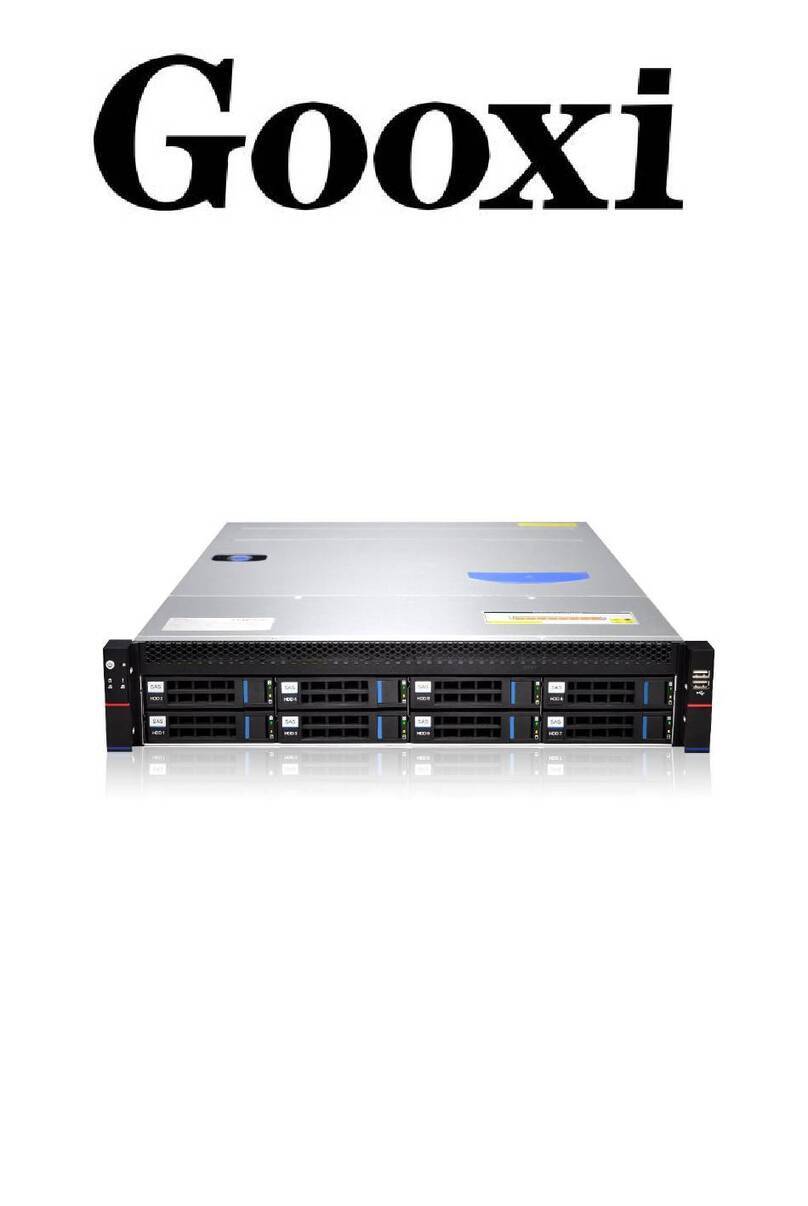
Gooxi ST401-S36REH-G2 Mounting instructions

ST401-S36REH-G2
Controller storage server barebones
User operation manual
Rev 1.0
Foreword
This manual is the controller storage system bare system ST401-S36REH-G2

Shenzhen Gooxi Technology Co., Ltd.
user's operation manual, mainly introduces the product characteristic
parameter, the system constitution, the installation way and the explanation,
this section controller storage server of Gooxi supports 1 controller module
The system is based on the integration of the 4U36 chassis and the G2SCW-4B
board.
This manual is for reference by professional system integrators and
personal computer technicians. This product should only be installed and
maintained by experienced technicians.
Manual framework
Chapter 1 Product Introduction
This chapter provides the specifications of the main components of the system
and describes the main features of the G2SCW-4B motherboard and the 4U36 chassis.
Chapter II System Interface Introduction
This chapter provides detailed description of the system interface, including
the main board's IO interface and each connector, terminal and jumper functions
and information.
Chapter 3 Detailed Controller Module Installation
This chapter provides the installation and description of the processor, memory,
PIKE card, and expansion card on the G2SCW-4B mainboard. Refer to this section for
precautions when installing or removing the processor, memory, PIKE card, expansion
card, and heat sink.
Chapter 4 Chassis Installation
This chapter provides the installation and description of the backplane, SPIB
board and fan wall on the storage server, and notes about installing or removing
the backplane, SPIB board, and fan wall. Refer to this section.
Chapter 5 Server System Installation
This chapter describes the necessary steps and precautions for using the
ST401-S36REH-G2 storage server barebones.

Shenzhen Gooxi Technology Co., Ltd.
Contents
Chapter 1 Product Introduction......................................................................................................4
1.1 System Features.............................................................................................................4
1.2 Board Features...............................................................................................................6
1.3 server chassis System Features...............................................................................7
1.4 System View.....................................................................................................................8
Chapter II System Interface Introduction................................................................................13
2.1 Overview.........................................................................................................................13
2.2 Motherboard IO Interface.........................................................................................16
2.3 Connection cable.........................................................................................................24
2.4 Jumper settings...........................................................................................................24
2.5 Power Module.................................................................................................................24
2.6 LED DEFINITIONS IN THE MOTHERBOARD .................................................................................25
Chapter 3 Detailed Controller Module Installation..............................................................30
3.1 The front view of the module.................................................................................30
3.2 The module opens the upper cover and the internal picture .......................30
3.3 CPU installation.........................................................................................................31
3.2 CPU Heatsink Installation.......................................................................................34
3.3 Memory Installation...................................................................................................35
3.4 Expansion Card Installation...................................................................................37
Chapter 4 Chassis Installation....................................................................................................40
4.1 Backplane and SPIB Board Installation...............................................................40
......................................................................................................................................... 45
4.2 Fan Installation.........................................................................................................45
4.3 Controller Module Installation.............................................................................47
4.4 Hard Disk Installation.............................................................................................49
Chapter 5 System Installation......................................................................................................52
5.1 Overview.........................................................................................................................52
5.2 System Steps.................................................................................................................52

Shenzhen Gooxi Technology Co., Ltd.
Chapter 1 Product Introduction
1.1 System Features
1.1.1 System Parameters
Model
ST401-S36REH-G2
processor
Intel Xeon processor E3-1200 V5/V6 series
Intel 6th Generation Core i3 /i5/i7 series
Pentium series,
Celeron series
Socket (LGA1151) up to 80W CPU
Key
applications
Cloud Storage Server System
Video storage server system
Big Data Cold Storage Server System
Security Monitoring IP-SAN Storage Server System
CDN acceleration system
Streaming Media Storage Server System
Outstanding
features
800W 1+1 Redundant White Gold Efficiency Power Supply
Supports 36 3.5" or 2.5" SAS2.0/SATA3.0 6Gb/s Hard Drives
High density, high performance, low cost, low power
consumption
Adopt IPMI2.0 dedicated Gigabit management LAN
Motherboard
G2SCW-4B
chipset
Intel PCH C232 chip
Memory
(system)
The system supports up to 64GB ECC DDR4-2133 UDIMMs
Expansion
Card
Supports one X16 PCI-E half-height expansion card (real
bandwidth PCIE X8)
SATA
Control module supports 2*SATA2.0 HDD, supports RAID 0,1
LAN
The system uses four Intel I210-AT 1GbE LAN Controllers
VGA
Aspeed AST2400 Graphics
Management
interface
IPMI 2.0 + KVM with dedicated LAN
power
supply
800W 1+1 Redundant Platinum Power Efficiency Power Supply,
Hot swappable
fan
Three easy-swapping 12038 fans (12V/Max1.76A)
Dimensions
4URack Mount,500mm*448mm*177mm

Shenzhen Gooxi Technology Co., Ltd.
1.1.2 System Overview
The ST401-S36REH-G2 barebones system is a 4U high-density, low-power,
controller-architecture storage product suitable for big data storage, cloud storage,
video surveillance network storage, and NAS storage.
The system hardware consists of three modules: hard disk modules, controller
modules, and power modules. The three modules are all hot-swappable, which
greatly reduces the cost of manual maintenance.
The main features of the product are summarized as follows:
The controller module supports two 2.5-inch SATA system hard disks
or SSDs.
Controller system uses Intel Greenlow platform, with LGA1151 CPU,
supports Intel Xeon Processor E3-1200 V5/V6 series, maximum
support 80W.
The system uses 800W1+1 redundant white gold brand efficiency
power supply and supports hot swapping and replacement.
The system uses three easy-swapping 12038 fans.
Chipset uses Intel PCH C232 chip.
The system has 4 Dual Channel DIMMs and supports up to 64GB ECC
UDIMMs.
The system uses four Intel I210-AT RJ45 Gigabit Ethernet ports.
The system uses a multiplexed IPMI management network port for
remote management. The BMC chip uses Aspeed AST2400.

Shenzhen Gooxi Technology Co., Ltd.
The system has a VGA port derived from the BMC.
The system has two USB3.0 interfaces for users to use.
1.2 Board Features
1.2.1 Board Parameters:
The ST401-S36REH-G2 is equipped with a G2SCW-4B single-processor server
board. It is based on the Intel X86 architecture, uses the Intel Greenlow platform, is
based on the Intel PCH C23X chipset, and is compatible with the latest-generation
Skylake CPU from Intel. It is compatible with Kabylake CPUs to be released, and
supports dual channels. DDR4-2133/1866/1600 ECC UDIMMs.
The following are the main features of G2SCW-BH:
Motherboard
G2SCW-4B
processor
Intel Xeon processor E3-1200 V5/V6 series
Intel 6th Generation Core i3 /i5/i7 series
Pentium series
Celeron series
Socket (LGA1151) up to 80W CPU
chipset
Intel PCH C232 chip
Memory
(system)
Supports up to 64GB ECC DDR3-2133/1866/1600 UDIMMs,
Capacity support 2GB, 4GB, 8GB, 16GB
PCH/SATA
Supports 6 SATA3.0 6Gb/s ports
LAN
4 Intel I210-AT 1GbE LAN Controllers
System hard
disk RAID
Intel® RSTe Support software RAID 0, 1
VGA
Aspeed AST2400 Graphics
Input/output
interface
1*VGA port, 4* Gigabit Ethernet port, 1* multiplexed IPMI
network port, 1* motherboard switch, 2*USB2.0
Management
interface
IPMI 2.0 + KVM with dedicated LAN

Shenzhen Gooxi Technology Co., Ltd.
1.2.2 motherboard hardware chip features diagram:
1.3 server chassis System Features
1.3.1 Chassis Parameters
Basic parameters
Chassis style
cabinet type
Chassis structure
4U
Adapt to the
motherboard
Gooxi G2SCW-4B
Hot-swappable
fans
not support
cooling system
3 12038 temperature controlled fans
Supports sliding
rail
Optional
Cabinet fixing
Loose screws
product material
High quality SGCC (galvanized steel sheet)
Chassis size
500mm * 448mm * 177mm (deep * wide * high)

Shenzhen Gooxi Technology Co., Ltd.
Package Size
800*580*395mm(length*width*height)
Safety certification
CE、ROHS
1.3.2 System Power
The chassis is equipped with 800W 1+1 redundant white gold efficiency power
supply and supports hot swapping and replacement.
Input AC voltage: 100V~240V;
DC output voltage: +12V, +12V_SB
Frequency: 47Hz~63Hz.
1.3.3 Heat Dissipation System
Three 12038 fans (12V/Max 1.76A)
Fan parameters:
Voltage: 8.5~13.2V, current: 1.60A, maximum 1.76A.
Power: maximum 23.2W.
Maximum speed: 3600 +/- 10% RPM.
Air flow: 4.657 m3/min (164.39 CFM), minimum 3.379 m3/min (119.3 CFM).
Pressure: 146.9538 Pa.
1.4 System View
1.4.1 Front View

Shenzhen Gooxi Technology Co., Ltd.
1.4.2 Rear view
1.4.3 Front Panel Indicators
The figure above shows the LED indicators of each module on the front panel.
Each module has its own status of LED display, described in the following table:
LED status description
No.
image
LED appearance
description
①
LOGO blue light is
always on
Device startup
②
Green light is on
Device startup

Shenzhen Gooxi Technology Co., Ltd.
③
Blue light is always
on
System ID indicator
④
Green light flashes
The system is operating
normally
⑤
Yellow light is always
on
Alarm indication. Including
system alarm, fan alarm,
power alarm, etc., which can
be viewed through IPMI
management software.
⑥
Green light is on
Network port 1 is connected
properly
⑦
Green light is on
Network port 2 is connected
properly
⑧
Blue light is always
on
Yellow light is always
on
Hard disk position indication
Hard disk alarm indication
⑨
Green light is on
Hard disk in place indication
1.4.4 Hard Disk Indicators
⑴Act LED (green light)
⑵Fault LED (yellow light)
⑶Status LED (blue light)
⑷LED description as shown below:
Act LED (green)
Fault LED (yellow)
Status LED (blue)

Shenzhen Gooxi Technology Co., Ltd.
Features
Green light
Blue light
Yellow light
Hard disk in
place
Chang Liang
OFF
OFF
Hard disk
activity
Flashing 4Hz/s
OFF
OFF
Hard disk
positioning
Chang Liang
Flashing 4Hz/s
OFF
Hard disk
error
Chang Liang
OFF
Chang Liang
RAID
reconstructi
on
Chang Liang
OFF
Flashing
1Hz/second
1.4.5 Hard Disk Sequence Introduction

Shenzhen Gooxi Technology Co., Ltd.

Shenzhen Gooxi Technology Co., Ltd.
Chapter II System Interface
Introduction
2.1 Overview
The main interfaces of the system are distributed on the main board. The
following content mainly introduces the interface layout of the main board.
2.1.1 G2SCW-4B MOTHERBOARD REAL PICTURE

Shenzhen Gooxi Technology Co., Ltd.
2.1.2 G2SCW-4B MOTHERBOARD INTERFACE AND DEFINITION:
1MOTHERBOARD INTERFACE LOCATION DIAGRAM:
2. Motherboard interface definition:
G2SCW-4B Single Board Connector
Connector
name
description
Board position
M.2 SSD
connector
75Pin M.2 SSD connector supporting PCIEX2
and SATA specification adaptive SSD
J19
JBAT1
Vertical Insert CR2032 Battery Holder
JBAT1
VGA Header
15PIN (2*8 No. 16) VGA Signal PIN Pin, VGA
Cable
J23
CPLD JTAG
CPLD JTAG connector for programming CPLD
programs
J10
SYS UART
BIOS (system) debugging 3pin serial port
J25
BMC UART
BMC debug 3pin serial port
J24
BIOS chip
8Pin BIOS debug socket and BIOS chip
U23
LAN1/NCSI
I210 1000M Data LAN port 1
Simultaneous use of NCSI as BMC IPMI LAN
port (100M)
J20
LAN2
I210 1000M Data LAN port 2
J20
LAN3
I210 1000M Data LAN port 3
J21

Shenzhen Gooxi Technology Co., Ltd.
LAN4
I210 1000M Data LAN port 3
J21
USB3.0
USB3.0 Stacked Double Connector
J28
DIMM A0
DIMM Channel A DDR4 SLOT0
J6
DIMM A1
DIMM Channel A DDR4 SLOT1
J7
DIMM B0
DIMM Channel B DDR4 SLOT0
J8
DIMM B1
DIMM Channel B DDR4 SLOT1
J9
CPU
LGA1151 CPU Socket
XU1
TPM/80Port
TPM/80Port pin for TPM module or
80port Debug running code card
J29
PCIEX16
PCIEX16 Slot Empty x8 pin, the actual CPU
PCIEX8
J13
PCIEX8
PCIEX8 Slot, actually connected to PCH
PCIEX4
J22
Mezzanine
Mezzanine connector, pinch connector to
PCIEX8 signal, for inserting PMC G8068M
or
LSI SAS3008 SAS12G Card
J31
Power Button
Motherboard boot pin, used when
debugging the motherboard
J30
Clear CMOS
Clear the CMOS pin, the default is not to
take the jump cap, plug in the jump cap is
valid
J16
ME Update
For ME upgrade pins, plug in jump cap
J18
ME Recovery
Force ME to restore to default status,
skip skip cap by default, insert skip cap
J17
SATA1
PCH SATA3.0 Port4 7Pin Connector
SATA1
SATA2
PCH SATA3.0 Port5 7Pin Connector
SATA2
SATA DOM
SATA DOM 3pin power connector
J27
HDD Power
5pin hard disk power connector for
connecting to the system hard disk board
to provide power
J26
Airmax high
speed signal
connector
Airmax VSe high speed signal hot swap
connector for high speed signal support
12Gb/s
J1/J2/J3
Airmax Power
Hot Plug
Connector
Airmax hot-swappable connector for
power transfer
J5

Shenzhen Gooxi Technology Co., Ltd.
Airmax hot
swap connector
guide pin
Airmax hot-swappable connector guide
pins for structural fixing and positioning
J4
2.2 Motherboard IO Interface
2.2.1 SWITCH BUTTON
Press the switch button to start the system, the position indicates the arrow
below
The button is the switch button and provides two kinds of system status
indicators to realize the power on and off functions of the whole system. When the
system is in the power on state, press this button to open the system; if the system
is in the on state, it is light Touch this button, you can turn off the system; if the host
is in a boot-up system state, long press this button to force the shutdown.
/ Note: After the system is plugged into AC power, please wait for the green
indicator light to flash, and then press this button to boot.
LED color status
LED
description
Green light 1Hz
blinks
Power AC power, the system is not turned on (the system is
plugged into AC power, the green light flashes after 30
seconds)
Green light
The system is operating normally
Orange light
Failure of the system, such as power supply, fan,
motherboard, etc. Details can be viewed on the IPMI
management interface.
not bright
System power AC terminal is not connected
2.2.2 SYSTEM ID (IDENTITY)INDICATOR
The system ID indicator is designed to allow the user to more intuitively
identify which device the current operation is on. The specific location of the

Shenzhen Gooxi Technology Co., Ltd.
system board is shown below. On the front of the motherboard, it is marked with
the D18 position:
2.2.3 IPMI LAN PORT
This network port is used for remote management and multiplexing of LAN1
and IPMI. It can be connected to the switch with CAT5 or above cables. It can also
be directly connected to the host of the customer. It supports Gigabit, 100Mbit, and
adaptive adjustment, but it cannot be used as a service data network. Used by
ports, the LED indicators of the network port are as follows:
IPMI LAN Port LED
LED
description
Left LED
Link status indicator:
1. Gigabit Link, green long bright

Shenzhen Gooxi Technology Co., Ltd.
2 hundred mega Link, orange long bright
3. Ten Mega Link, LED is not bright
Right LED
Yellow light flashes when there is data activity
This indicator is off when there is no data activity
Location map:
2.2.4 LAN PORT
The mainboard provides two Gigabit Ethernet ports (J19 location). The main
chip adopts Intel I210-AT, self-adaptive 1000M, 100M, and 10M. The main board
has two Gigabit service network ports for receiving/sending service data, using
CAT5 and its The above cable access switch can also be directly connected to the
customer's host. The LED indicators of the network port are as follows:
Business Data LAN Port Led
LED
description
Left Led
Link status indicator:
1. Gigabit Link, long green light;
2. One hundred trillion links, orange long
light;
3. Ten mega Link, LED is off;
Right Led
The yellow light flashes when there is
data activity;
When no data activity, the indicator does
not light;
/ Note: The two network port indicators are the same.
Network port location diagram:

Shenzhen Gooxi Technology Co., Ltd.
2.2.5 USB INTERFACE
Four external USB 2.0 ports (J22, J24) for accessing USB 2.0 Type A devices,
such as USB keyboards, USB drives, etc. The following is the USB PIN angle
definition:
USB2.0 Connector
PIN sequence
description
PIN1,5
5V
PIN2,6
D-
PIN3,7
D+
PIN4,8
Ground
Location map:
2.2.6 VGA DISPLAY INTERFACE
The motherboard graphics chip uses AST2400, AST2400 built-in PCIE VGA
Controller, a 15PIN VGA Connector is used to access the VGA monitor, this VGA port
is connected from the motherboard's VGA pin to the VGA cable to be fixed in the
controller casing IO position .

Shenzhen Gooxi Technology Co., Ltd.
2.2.7 SATA INTERFACE
The motherboard is designed with two SATA connectors, all from the Intel PCH.
This system comes standard with a C232 PCH chip.
The location diagram is as follows:
SATA Connector Pin Definition
PIN sequence
description
PIN1
Ground
PIN2
SATA HOST TX+
PIN3
SATA HOST TX-
PIN4
Ground
PIN5
SATA HOST RX-
PIN6
SATA HOST RX+
PIN7
Ground
2.2.8 SATA DOM POWER CONNECTOR (J26 POSITION)
The motherboard design reserved 3PIN Power Connector for SATA DOM access
power.
PIN is defined as follows:
SATA DOM POWER Connector Pin Definition
PIN sequence
description
PIN1
5V
Table of contents
Other Gooxi Server manuals

Gooxi
Gooxi SL101-D04R-G3 User manual

Gooxi
Gooxi SY103-S06R-G2 Mounting instructions

Gooxi
Gooxi Purley Platform 1U User manual

Gooxi
Gooxi RMC4136-670-HSE User manual

Gooxi
Gooxi RMC2108-670-HS User manual

Gooxi
Gooxi SR401 4U User manual

Gooxi
Gooxi SR201 2U User manual

Gooxi
Gooxi SL201 User manual

Gooxi
Gooxi RMC2108-670-HS User manual

Gooxi
Gooxi SL201-G4 User manual