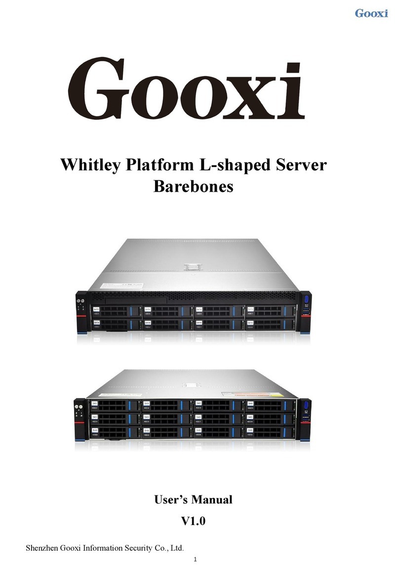
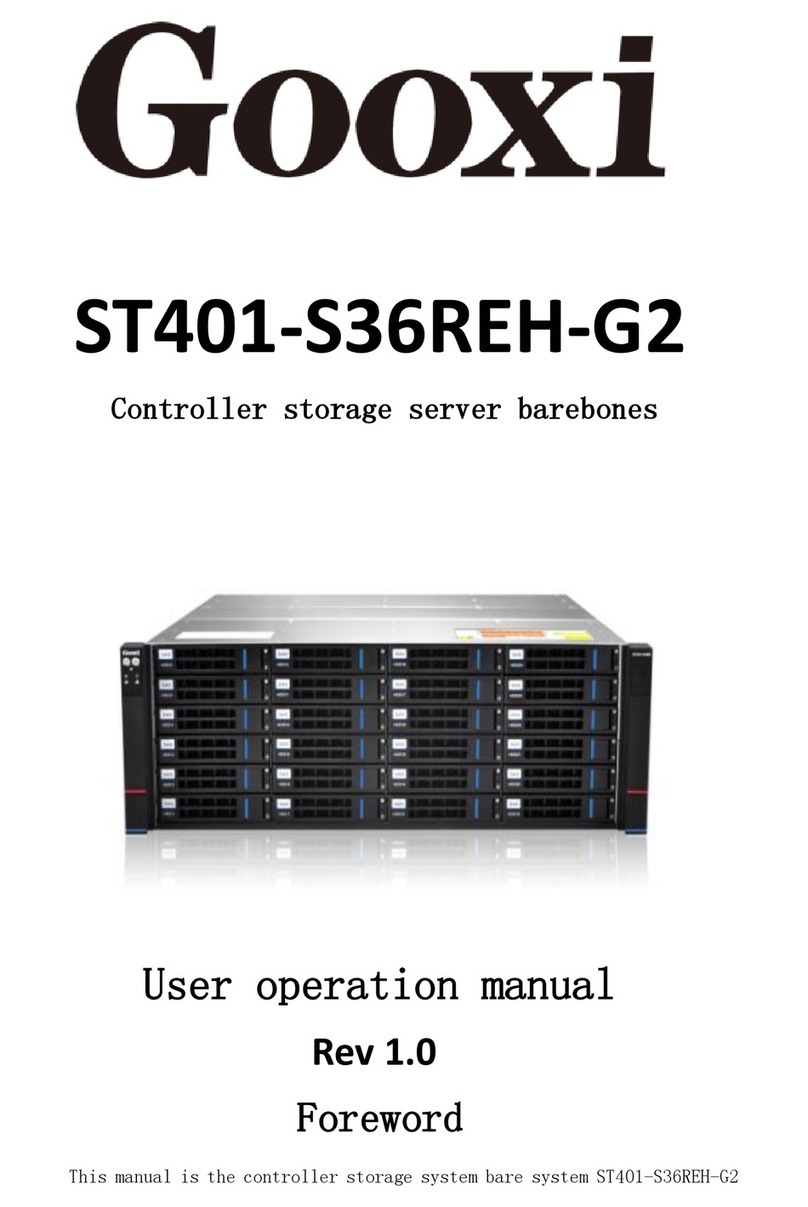
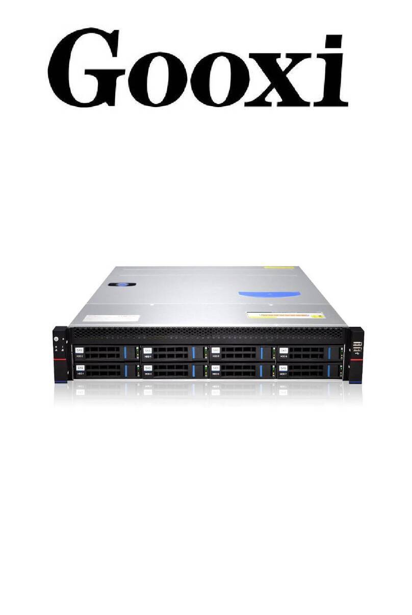
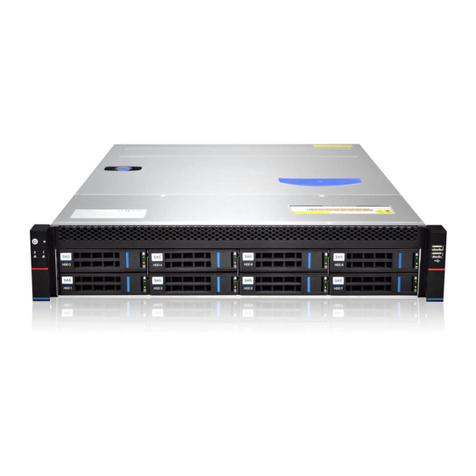
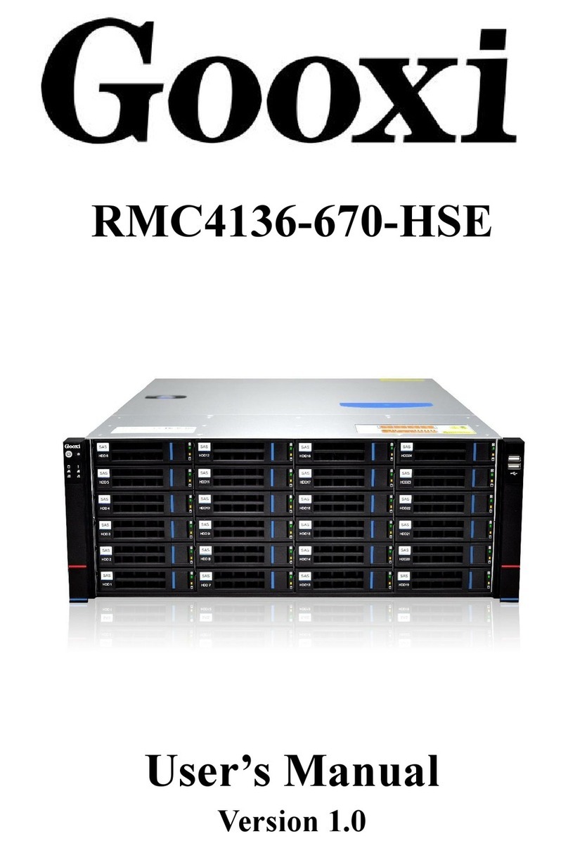
Gooxi Purley Platform 1U User manual

Purley Platform 1U L-Shape Server Product Manual REV 1.0

All trademarks used in this manual are the property of the trademark owner
Intel, Pentium4, PentiumD, Xeon, Core and Celeron are registered trademarks of Intel
Microsoft, MS-DOS, and Windows XP/NT/2000/2003 are registered trademarks of Microsoft
AMD, Opteron is a registered trademark of AMD
Netware is a registered trademark of Novell
Award is a registered trademark ofAward Software Inc
IBM, VGA, PS/2, and OS/2 are registered trademarks of International Business Machines
Sound Blaster is a registered trademark of Creative Technology Ltd
PC-Cillin and ChipAway Virus are registered trademarks of Trend Micro Inc
AMI is a registered trademark ofAmerican Megatrends Inc
A3D is a registered trademark of Aureal Inc
Gamut is a registered trademark of Formosoft International Inc
Super Voice is a registered trademark of Pacific Image Communications Inc
MediaRing Talk is a registered trademark of MediaRing Inc
All other trademarks appearing in this manual have been registered. The third party's registered
trademark is owned by a third party.
The specifications and information stated in this manual will change according to the specifications.
Any changes are also compiled according to future versions.
Therefore, the manufacturer does not have to assume the responsibility of making the contents of
the manual erroneous or omission due to the specification update.
The information in this manual may contain technical or typographical errors.
The pictures in this manual may differ from the actual ones and are for illustrative purposes only.
We reserve the right to make improvements/changes to our products without notice.

This manual is the product technical manual of Purley 1U dual cabinet server. It mainly
introduces the technical characteristics, system architecture, installation method and basic
operation of this product. Purley 1U dual cabinet server is divided into 1U4 disk and 1U10
disk. With two models, the product features low energy consumption, flexible expansion,
high reliability, easy management, and ease of deployment.
This manual is for reference by professional system integrators or professional technicians.
This product should be installed and maintained only by experienced technicians approved
by Guoxin.
Manual framework
Chapter 1 Safety Statement
This section describes some of the environmental conditions that need to be taken
into account when using this product, precautions, and explanations of laws and
regulations related to the product.
Chapter II Product Introduction
This chapter provides the specifications of the main components of the system
and describes the main features of each model of the Purley 1U dual cabinet
server.
Chapter 3 Installing System Components
This section describes the installation methods and major considerations for using
the major system components of the Purley 1U Dual cabinet Server.
Chapter IV System cabinet Installation
This section describes the procedures and precautions for installing the rack using
the rails that are shipped with the Purley 1U Dual cabinet Server.
Chapter 5 Cable Connection Instructions
This chapter describes the connection of the main cables of the Purley 1U dual
cabinet server 1U4 bay and 1U10 bay bay system.
Chapter 6 BIOS Parameter Setting Instructions
This chapter mainly introduces the system BIOS parameter settings and main

functions.
Chapter 7 RAID Setup Instructions

This chapter mainly describes how to set up RAID.
Chapter 8 Rapid IPMI Deployment
This chapter focuses on how to quickly deploy IPMI.
Chapter 9 Jumper Setting Instructions
This chapter focuses on the layout of the Purley 1U Dual cabinet Server Board and
pin jumper setup instructions.
Chapter 10 Product Specifications
This chapter focuses on the main technical specifications of the Purley 1U dual
cabinet server product.

Manual framework..........................................................................................2
Chapter 1 Safety Statement.............................................................................1
1.1 General safety issues ...............................................................1
1.2 Product toxic and hazardous substances or elements name
and content identification table..............................................................2
1.3 Warning notice...........................................................................5
1.4 Climate environment requirements.........................................5
1.5 Other important description.....................................................6
Chapter II Product Introduction........................................................................7
2.1 system introduction..............................................................................7
2.2 System Configuration ..........................................................................7
2.3 System model specifications .............................................................10
2.4 System components introduction ......................................................13
Chapter 3 Installing System Components .....................................................26
3.1 CPU installation .................................................................................26
3.2 Radiator installation...........................................................................28
3.3 Memory installation............................................................................28
3.4 Hard disk installation..........................................................................30
3.5 Front hard disk backplane installation...............................................32
3.6 M.2 SSD installation ..........................................................................34
3.7 PCI-E module installation ..................................................................35
3.8 Network module installation...............................................................36
3.9 Power module installation..................................................................39
3.10 PCI-E expansion card installation....................................................40
3.11 Fan module installation....................................................................41
3.12 Windshield installation.....................................................................42
3.13 Optical drive installation...................................................................43
3.14 Chassis cover installation................................................................44
Chapter IV System cabinet Installation .....................................................46
Chapter 5 Cable Connection Instructions......................................................51
5.1 1U4 model front panel connection.................................................51

5.2 1U4 bay 3.5-inch disk model motherboard to the backplane
directly connected SATA model alignment instructions...................51
5.3 1U4 bay 3.5-inch disk SAS card to backplane model alignment 53
5.4 1U4 bay 3.5-inch disk type Raid card to backplane model
alignment................................................................................................55
5.5 1U10 tray type front panel connection..........................................56
5.6 1U10 bay main board to backplane direct connection SATA
model alignment description................................................................57
5.7 1U10 disk SAS card to backplane direct connection ..................58
5.8 1U10 tray Raid card to the back of the direct connection model
description..............................................................................................59
5.9 1U10 disk Raid card + SAS card to the backplane direct
connection..............................................................................................60
5.10 1U10 tray Raid card + motherboard to backplane direct
connection..............................................................................................62
Chapter 6 BIOS Parameter Setting Instructions............................................64
6.1 Enter BIOS Setup interface...............................................................64
6.2 Setup menu parameter description ...................................................64
6.3 User operation reminder..................................................................130
Chapter 7 RAID Setup Instructions..............................................................130
7.1 PCH group RAID..............................................................................130
7.2 LSI SAS3008 Group RAID...............................................................151
7.3 LSI 9361-8i Group RAID..................................................................167
Chapter 8 Rapid IPMI Deployment..............................................................269
8.1 Rapid deployment of IPMI ...............................................................269
8.2 IPMI function quickly explain ...........................................................275
Default username and password.................................................................276
KVM page introduction.................................................................................280
Remote control shortcuts.............................................................................282
8.3 Other ways to connect IPMI.............................................................286
Chapter 9 Jumper Setting Instructions.........................................................286
9.1 Motherboard line layout instructions.......................................286
Chapter 10 Product Specifications...............................................................283

<1>
Chapter 1 Safety Statement
1.1 General safety issues
To prevent the risk of major personal and property damage, please be sure
to follow the suggestions below.
Do not open the cover of the system by yourself and it should be operated by a
professionally trained service technician. Parts of the triangle marked with a
lightning symbol may have high voltage or electric shock. Do not touch it.
Remember to disconnect all cables before proceeding. (There may be
more than one cable)
It is forbidden to carry out live operation such as starting the machine before the
cover is closed.
When you need to open the lid, please wait for the internal equipment to cool
before performing it, otherwise it will be easy to cause burns to you.
Do not use this equipment in a humid environment.
If an extension cable needs to be used, use a three-wire cable and make sure it is
properly grounded.
Make sure the computer is well grounded. Different grounding methods can be
used, but they must be physically connected to the ground. If you are not sure if
you have a safe grounding protection, contact the appropriate agency or
electrician for confirmation. If you need to reel cable wiring, please contact
Guoxin company for advice.
Please use a three-core power cord and socket with grounding protection.
Improper grounding may result in leakage, explosion, or even personal injury.
Make sure that the power socket and the power socket are in close contact.
Loose contact may cause a fire.
Using your computer under AC voltage of 220V, working at unsuitable voltages
may result in electric shock, fire, and damage to the computer.
Require the computer to be well-ventilated and away from sources of heat, fire,
and heat sinks. Otherwise, the computer may cause smoke, fire, or other damage
due to overheating.
If you smell or see the computer smoking, turn off the computer immediately and
unplug the power cord.

<2>
It is required that the power cord can be easily plugged in and unplugged from the
power supply and power outlet. Please keep the power cord and plug clean and
undamaged, otherwise there may be a risk of electric shock or fire.
Note: If the battery is replaced incorrectly, there is a risk of explosion. Only
use the replacement of the same or equivalent type recommended by
the manufacturer. The used battery will cause environmental
pollution. Replace the old battery and follow the instructions.
Keep the computer away from electromagnetic fields.
Stay away from electronic noise caused by high-frequency safety equipment such
as large air-conditioning fans, large motor TV stations, and transmission towers.
Do not plug or unplug the backplane or move the computer while the computer is
running. Doing so may cause the computer to crash or damage the components.
Please try to avoid frequent restart or switch on and off to extend the life of your
computer.
Please keep the environment clean and avoid dust. The working temperature of
the equipment is 10°C~35°C and the humidity is 35%~80%.
Please promptly back up important data. Gooxi Technology Co., Ltd. is not
responsible for data loss caused by any situation.
This product uses an optical drive as a Class 1 laser device.
1.2 Product toxic and hazardous substances or elements name and
content identification table
During the 10-year environmental protection use period, toxic or hazardous
substances or elements contained in the product will not leak or mutate under
normal use conditions. Users of electronic information products will not cause
serious environmental pollution or Personal and property causes serious damage.

<3>
Part Name
Harmful Substance
lead
HG
cadmi
um
Hexava
lent
chromiu
m
Polybromin
ated
biphenyls
PBDE
(Pb)
(Hg)
(Cd)
(Cr VI)
(PBB)
(PBDE)
Chassis/Baffl
e
X
O
O
O
O
O
Mechanical
components
(fans,
radiators,
motors, etc.)
X
O
O
O
O
O
Printed
Circuit
Components
- PCA*
X
O
O
O
O
O
Cable/wire/c
onnector
X
O
O
O
O
O
Hard disk
drive
X
O
O
O
O
O
Part Name
Harmful Substance
lead
HG
cadmi
um
Hexava
lent
chromiu
m
Polybromin
ated
biphenyls
PBDE
(Pb)
(Hg)
(Cd)
(Cr VI)
(PBB)
(PBDE)

<4>
Media
reading/stora
ge
equipment
(disc, etc.)
X
O
O
O
O
O
Power
Supply/Powe
r Adapter
X
O
O
O
O
O
power cable
X
O
O
O
O
O
Pointing
device
(mouse, etc.)
X
O
O
O
O
O
keyboard
X
O
O
O
O
O
UPS
X
O
O
O
O
O
Complete
cabinet / Rail
Products
X
X
O
O
O
O
○ Indicates that the content of the toxic and hazardous substances in all
homogeneous materials of the component is below the limit requirements
specified in GB/T 26572-2011 "Limitations of Restricted Substances in Electrical
and Electronic Products".
× indicates that the content of the toxic and hazardous substances in the
homogeneous material of the component at least exceeds the limit requirements
specified in GB/T 26572-2011 “Limitations of Restricted Substances in Electrical
and Electronic Products”. However, it complies with EU RoHS directive
(including its exemption clause).
Note: This table shows the status of toxic and hazardous substances
contained in all possible components of Guoxin's servers, storages,
and workstations. Customers can refer to this table to check the
status of toxic and hazardous substances contained in the purchased

<5>
parts.
1.3 Warning notice
This product meets the national CCC certification standards.
1.4 Climate environment requirements
The optimal working temperature of the equipment is 10°C-35°C; the
maximum indoor temperature of the equipment is 40°C.
System battery
3 V CR2032 lithium battery.
Note: Some configurations have been verified for performance at 45°C and
90% (29°C maximum dew point) humidity.
temperature
Operating
temperature
10 °C to 35 °C (50 °F to 95 °F) with a maximum
temperature gradient of 10 °C per hour
Continuous
operating
temperature range
(at 950 meters or
3117 feet below
altitude)
10 °C to 35 °C (50 °F to 95 °F) without direct sunlight.
Storage
temperature range
–40°C to 65°C (–40°F to 149°F)
humidity
storage
With a maximum dew point of 33 °C (91 °F), the relative
humidity is 5% to 95%. The air must not condense at
all times.
Continuous
operation humidity
percentage range
With a maximum dew point of 26 °C (78.8 °F), the
relative humidity is 10% to 80%.

<6>
If the computer is used in an environment where the lightning protection
facilities are poor or not, turn off the power and remove the power cord,
network cable, and telephone line connected to the computer in a
thunderstorm.
Please use genuine operating system and software and configure it correctly.
Gooxi Technology Co., Ltd. does not assume maintenance responsibility for
server failures caused by operating systems and software.
Please do not disassemble the chassis and increase or decrease the server
hardware configuration. Gooxi Technology Co., Ltd. is not responsible for the
hardware and data damage caused by this.
When a server fails, first check the Troubleshooting section of this manual to
identify and troubleshoot common problems. If you cannot determine the
cause of the problem, contact the Gooxi Technology Support Department
immediately for assistance.
Choosing a suitable environment for the computer helps the computer run
stably and can extend the life of the computer.
Gooxi Technology Co., Ltd. reserves the right of final interpretation of the above terms and
conditions
1.5 Other important description
"If the device is marked with an identifier, it means that the device affixed with
this identifier is designed and evaluated only at an altitude of 2000m.
Therefore, it is only suitable for safe use below 2000m. When it is used
above 2000m, there may be a safety hazard."
“If this device is marked with this symbol, it means that the device affixed with
this symbol is only designed and evaluated for safety in non-tropical climate
conditions. Therefore, it is only applicable to the safe use of non-tropical
climatic conditions and may be safe when used in tropical climate conditions.
Hidden trouble."

<7>
Chapter II Product Introduction
2.1 system introduction
The Purley 1U dual cabinet server is a new generation of 1U dual-channel cabinet
server with a wide range of uses that Taiyi uses for the Internet, IDC (Internet Data
Center), cloud computing, enterprise market, and telecom service applications.
Suitable for IT core business, cloud computing virtualization, high performance
computing, distributed storage, big data processing, enterprise or telecom service
applications and other complex workloads. The server has the advantages of
low energy consumption, strong scalability, high reliability, easy management, and
easy deployment.
2.2 System Configuration
The Purley 1U dual cabinet server product includes 1U4 (3.5" hard disk) and
1U10 (2.5" hard disk). The two models are the same except for the hard disk
connection method and the maximum number of compatible hard disks.
2.2.1System parameters
Features
Technical specifications
model
1U
size
1Ucabinet type, standard guide rails, maximum depth: 788 mm, including 808 mm lugs
processor
Supports 1 or 2 Intel SkyLake LGA3647 Xeon processors, supports Xeon series processors
with OPA, (up to TDP 165W, optionally supports TDP 205W)
chipset
Intel® C620 Series Server-Specific Chipset
RAM
Support DDR4 ECC RDIMMs/LRDIMMs server memory, memory frequency support
1866/2133/2400/2666MHz
Supports 12 DDR4 channels, each channel supports 2 DIMMs, a total of 24 DDR4 slots
Supports single capacity of 8GB, 16GB, 32GB, 64GB, 128GB, maximum support of 3.0TB
(need to match -M processor) memory capacity
Storage
controller
Internal storage controller: PCH supports RAID 0\1\10&5, optional 12 Gbps RAID
\1\5\6\10\50\60 (1G/2G/4G cache)
External HBA (non-RAID): 12 Gbps SAS HBAs

<8>
Internal storage: 1 PCIe 3.0 x4 M.2 slot, 2 Mini SSD slots (SATA DOM)
driver
Front Bay: Up to 10 hot-swap 2.5-inch SAS/SATA (HDD/SSD)
Or up to four 3.5-inch SAS/SATA (HDD/SSD)
NVMe Support: Up to 10 hot-plug 2.5-inch NVMe/SAS/SATA (SSD/HDD)
power supply
Platinum-class 550W, 800W, 1300W, 1600W hot swappable redundant power supply with
optional support for 240v and 338v DC
External Port
& PCIE
Front port: VGA, 2 USB3.0 (1U10 only supports 1), 1 LCD dedicated Mini USB
Rear: VGA, 2 USB3.0, 1 management network port, 2 RJ45 network ports
PCIE expansion board: up to 4 PCIE third generation slots
System fan
N+1 hot swap redundant fan
The internet
Two onboard 1GE, two optional 1GE/4 1GE/2 10GE/4 10GE/2 40GE network daughter
cards
safety
TPM/TCM (optional)
Chassis cover intrusion detection
Front panel with key lock
Locking the chassis cover
management
Onboard iBMC management module supporting management features such as IPMI, SOL,
KVM Over IP, and virtual media
Optional LCD Management Module
Supported
operating
systems
Microsoft Windows Server、Red Hat Enterprise Linux、SUSE Linux Enterprise Server、
CentOS、Citrix Xen Server、Vmware ESXi、Linux KVM、Ubuntu
Actual version please contact Guoxin sales
Virtualization
support
VMWare ESXi 6.0
temperature
Standard operating temperature: 5oC - 35oC (without direct sunlight)
Extended operating temperature: 5oC - 40oC (limited configuration meets)
Storage Storage Temperature: -40oC - 65oC
humidity
Operating Humidity: 30% - 80% (non-condensing)
Storage humidity: 5% - 95% (non-condensing)

<9>
2.2.1system structure
Purley 1U dual cabinet server with Intel Purley platform, with Intel Xeon SkyLake CPU; support 12 DDR4
Channel, 24 DDR4 slots; maximum support 3.0TB (with -M processor) memory capacity;
The main board features are as follows:
CPU uses Intel LGA3647-P0 SKY-LAKE processor; (Remark: CPU supports normal and SKY-Fabric
processors.)
Each CPU supports six channels of DDR4, two DIMMs per channel, RDIMM/LRDIMM. Each CPU
supports a maximum capacity of 1.5TB;
DDR4 type: DDR4-1866/2133/2400/2666 ECC-RDIMM, ECC-LRDIMM;
There are three PCIE RISER slots on the board. Among them: RISER1 24 PCIE LANs are all from
CPU1, RISER2's 24 LANEs are from CPU2, and RISER3's 16 PCIE LANEs are also from CPU2.
There are two MEZZANINE CONNs on the main board to insert SAS daughter boards and I/O
daughter boards. The supported SAS daughter boards include: LSI3008 and PMC8068; Supported I/O
daughter boards: I350-AM2/AM4, JL82599ES, X710L -BM1, X710L-BM2;
One PCIE PORT: X4 LANE-to-PCIE M.2 SLOT leads from the CPU 1 on the mainboard, supporting
PCIE M.2 storage media;
Two Gigabit BASE-Ts are integrated on the main board and Intel I350-AM2 chips are used from CPU1;
Southbridge PCH adopts INTEL LEWISBURG C620 series chipset;
PCH leads to 14 SATA ports, the highest rate: 6Gb / s, compatible with SATA 1.5Gb / s, 3.0Gb / s;
SATA Controller out of 8 SATA PORT, and SSATA out of 6 SATA PORT, which SATA PORT 8 PORT,
according to Sequentially introduced into two SFF8643 connectors, and the first four PORTs of SSATA are
introduced into one SFF8643 connector, and the second two PORTs are introduced into the 7PIN SATA
connector to access the SATA DOM and DVD;
The BMC chip in the single board adopts ASPEED's AST2500 control chip for remote IPMI
management. Debug port, VGA output port, dedicated Gigabit RJ45, and RMII/NCSI connection to
I350-AM2 for sharing I350-AM2's two network ports.
The system architecture board diagram is as follows:

<10>
2.3 System model specifications
1U4 bay 3.5 inch disk model
(positive)

<11>
(anti)
product
name
1U4 (3.5" hard disk)
processor
Supports 1 or 2 Intel SkyLake LGA3647 Xeon processors, supports Xeon series
processors with OPA, (up to TDP 165W, optionally supports TDP 205W)
Motherboard
model
T1DM-E2
chipset
Intel® C620 Series Server-Specific Chipset
Memory
(system)
Support DDR4 ECC RDIMMs/LRDIMMs server memory, memory frequency support
1866/2133/2400/2666MHz;
Support 12 DDR4 Channels, each Channel supports 2 DIMMs, a total of 24 DDR4 slots;
Supports single memory capacity of 8GB, 16GB, 32GB, 64GB, 128GB, and maximum
support of 3.0TB (with -M processor required);
Expansion
Card
1. Maximum support for expansion of 2 PCIE slots x16;
2. Supports up to 2 full-height half-length PCI-EX16 GPUs;
3. In addition, it can also support 1* non-standard PCIEX8 SAS/RAID card slot+1*
non-standard PCIEX8 card slot;
hard disk
Supports up to four 3.5-inch SAS/SATA (HDD/SSD)
Optical drive
Supports 1 optical drive;
M.2 SSD
PCIE Gen3 X4 M.2 SSD(Support M.2 SSD length 80mm and 110mm)
LAN
Two onboard 1GE, two optional 1GE/4 1GE/2 10GE/4 10GE/2 40GE network daughter
cards
External
port
Front port: VGA, 2 USB3.0, 1 Mini USB for LCD
Rear: VGA, 2 USB3.0, 1 management network port, 2 RJ45 network ports
managemen
t
Onboard iBMC management module supporting management features such as IPMI,
SOL, KVM Over IP, and virtual media
Optional LCD Management Module
System fan
N+1 hot swap redundant fan
power
supply
Platinum-class 550W, 800W, 1300W, 1600W hot swappable redundant power supply
with optional support for -48V, 240V, and 338V DC
Dimensions
1Ucabinet type, standard guide rails, maximum depth: 788 mm, including 808 mm lugs

<12>
1U10 disk position 2.5 inch disk model
(positive)
(anti)
product name
1U10 (2.5" hard disk)
processor
Supports 1 or 2 Intel SkyLake LGA3647 Xeon processors, supports Xeon series
processors with OPA, (up to TDP 165W, optionally supports TDP 205W)
Motherboard
model
T1DM-E2
chipset
Intel® C620 Series Server-Specific Chipset
Memory
(system)
Support DDR4 ECC RDIMMs/LRDIMMs server memory, memory frequency
support 1866/2133/2400/2666MHz;
Support 12 DDR4 Channels, each Channel supports 2 DIMMs, a total of 24 DDR4
slots;
Supports a single capacity of 8GB, 16GB, 32GB, 64GB, 128GB, and a maximum of
3.0TB (must match M processor) memory capacity;
Expansion Card
1. Maximum support for expansion of 2 PCIE slots x16;
2. Supports up to 2 full-height half-length PCI-EX16 GPUs;
Table of contents
Other Gooxi Server manuals

Gooxi
Gooxi RMC2108-670-HS User manual

Gooxi
Gooxi SR201 2U User manual

Gooxi
Gooxi ASR4105G-D12R User manual

Gooxi
Gooxi SR401 4U User manual

Gooxi
Gooxi SR4108G4U User manual

Gooxi
Gooxi SR101 1U User manual

Gooxi
Gooxi SL201 User manual

Gooxi
Gooxi SL101-D04R-G3 User manual

Gooxi
Gooxi R Series User manual

Gooxi
Gooxi RMC2108-670-HS User manual
Popular Server manuals by other brands

IBM
IBM System x3250 M3 Type 4251 Product guide

Intel
Intel R2000WF series Technical product specification

HP
HP EH920A - StorageWorks Ultrium 1760 Tape... Start here

Perle
Perle IOLAN DS1 Cli reference guide

Intellisystem
Intellisystem IT404 Quick installation guide

Dell
Dell PowerEdge T320 Rack Installation Instructions