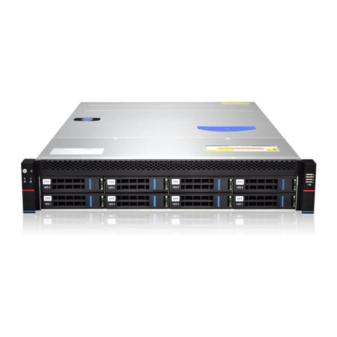
Gooxi SL201-G4 User manual

SL201-G4 Rackmount Server
User Manual
Document version:01
Release date:2023/12/20
Shenzhen Gooxi Information Security Co., Ltd.

1
Statement
© Shenzhen Gooxi Information Security Co., Ltd. All rights reserved.
This user manual, including but not limited to all information contained herein, is
protected by copyright law. Without the permission of Shenzhen Gooxi Information
Security Co., Ltd. (hereinafter referred to as "Gooxi"), no one may engage in any
behavior such as imitation, copying, excerpting, forwarding, or other forms of
utilization.
Gooxi provides this user manual "as is" and to the extent permitted by law, makes no
express or implied warranties or guarantees, including but not limited to
merchantability, fitness for a particular purpose, non-infringement of any rights of
others, and any warranties or guarantees regarding the use or inability to use this user
manual. Gooxi also does not provide any warranties or guarantees regarding the
accuracy or reliability of any information obtained using this user manual.
Due to product version upgrades or other reasons, the content of this user manual may
be periodically updated. Unless otherwise specified, this user manual is provided
solely as a usage guide, and users shall bear all risks associated with the use of this
user manual.
Gooxi® is a trademark of Shenzhen Gooxi Information Security Co., Ltd.
Microsoft® and Windows is a trademark of the Microsoft group of companies.
Linux® is a registered trademark of Linus Torvalds.
Aspeed® is a trademark of ASPEED Technology Inc.
Ownership of other trademarks belongs to their respective owners.

2
Foreword
This manual is the product technical manual for the Gooxi Eagle Stream platform 2U
model servers. It primarily provides an introduction and explanation of the product's
appearance, structure, hardware installation, and basic configuration.
Please note that this manual is intended for reference and research purposes for professional
technical personnel. The installation and maintenance of this product should only be performed
by experienced technical personnel.
Modification Record
Manual
version
Release date
Modification instructions
V1.0
2023-12-20
/

3
Contents
Statement............................................................................................................................................. 1
Foreword..............................................................................................................................................2
1. Product Introduction ....................................................................................................................... 5
1.1 Product Overview ................................................................................................................. 5
1.2 Product Structure .................................................................................................................. 6
1.3 Logical Structure .................................................................................................................. 7
1.4 Product Specifications .......................................................................................................... 8
2. Hardware Description .....................................................................................................................9
2.1 Front Panel ............................................................................................................................9
2.1.1 Appearance .............................................................................................................. 9
2.1.2 Indicator lights and buttons ................................................................................... 9
2.1.3 Interface ................................................................................................................. 11
2.2 Rear Panel ..........................................................................................................................11
2.2.1 Appearance ............................................................................................................ 11
2.2.2 Indicator lights and buttons ................................................................................. 12
2.2.3 Interface ................................................................................................................. 12
2.3 Processor ........................................................................................................................... 14
2.4 Memory ..............................................................................................................................15
2.4.1 Memory slot location ............................................................................................15
2.4.2 Memory installation guidelines ........................................................................... 16
2.5 Storage ...............................................................................................................................16
2.5.2 Hard drive serial number ......................................................................................17
2.5.3 Hard drive status indicator ...................................................................................17
2.6 Power Supply ....................................................................................................................17
2.7 Fans .................................................................................................................................... 18
2.8 I/O Expansion ..................................................................................................................... 19
2.8.1 PCIe slot location ..................................................................................................19
2.8.2 PCIe slot description .............................................................................................19
2.8.3 PCIe Expansion Module .......................................................................................20
2.9 PCBA ................................................................................................................................. 22
2.9.1 Motherboard .......................................................................................................... 22
2.9.2 Hard drive backplane ............................................................................................23
3. Installation Instructions ................................................................................................................ 26
3.1 Chassis Top Cover Installation ....................................................................................... 26
4
3.2 Installation of Accessories .............................................................................................. 26
3.2.1 CPU installation .................................................................................................... 26
3.2.2 Heatsink installation ............................................................................................. 27
3.2.3 Memory installation ..............................................................................................27
3.2.4 Server slide rail installation ................................................................................. 28
4. Configuration Instructions ............................................................................................................31
4.1 Initial Configuration ........................................................................................................ 31
4.1.1 Power on and start .................................................................................................31
4.1.2 Initial data ..............................................................................................................33
4.1.3 Configure BIOS .....................................................................................................33
4.1.4 Configure BMC .....................................................................................................34
Appendix............................................................................................................................................39

5
1. Product Introduction
1.1 Product Overview
SL201-G4 Series 2U Dual-socket Rack-Mount Server is a new generation of
versatile 2U dual-socket rack-mount servers launched by Gooxi to meet the needs of
the Internet, IDC (Internet Data Center), cloud computing, enterprise markets, and
telecom business applications. It is suitable for core IT operations, cloud computing
virtualization, high-performance computing, distributed storage, large-scale data
processing, enterprise or telecom business applications, and other complex workloads.
This server features low power consumption, strong expandability, high reliability, easy
management, and deployment. Its main configurations include:
Supports 2 Intel Xeon Scalable processors of the 4th generation.
Supports 32 DIMM DDR5 memory slots.
Offers 1 panel chassis options: 12*3.5-inch hard drive bays.
The rear window supports expanding with 4*2.5-inch hard drive slots.
Supports up to 10 PCIe expansion slots and 2 OCP network card slots.
The physical illustration of the server with a 12-drive configuration is shown below:
Front view 1-1
Rear view 1-2

6
1.2 Product Structure
Eagle Stream 2U Dual-Socket Rack-Mount Server Exploded View (Illustration based on the
12-bay model).
Structure diagram 1-3
Table 1-1
No.
Name
No.
Name
1
Hard Drive
8
Fan Bracket
2
Hard Drive Bracket
Module
9
Top Cover
3
Air Guide Module
10
Full-Height PCIe Module
4
Hard Drive Backplane
11
Half-Height PCIe Module
5
Fan Module
12
2.5-inch Hard Drive Module
6
Memory Stick
13
OCP3.0
7
CPU Heatsink
14
Power Supply Module

7
1.3 Logical Structure
The logic of the SL201-G4 Series Dual-Socket Rack-Mount Server is as shown in
the following diagram:
Motherboard logic block diagram 1-4
The CPU adopts the 4th generation Intel Xeon Scalable processor, LGA4677
socket.
Each CPU supports 8 channels, and each channel supports 2 DDR5
RDIMM/LRDIMM memories.
Onboard 2 M.2 slots (supports 22110/2280 specifications), only supports SATA
signals.
PCH uses INTEL C740 series chipset.
The BMC chip uses ASPEED's AST2600 control chip for IPMI remote
management. VGA output port, dedicated Gigabit RJ45 management network port,
and connection to PCH through RMII/NCSI.

8
1.4 Product Specifications
Table 1-2
Product Model
SL201-D12R-NV-G4
Product Type
2U 12-bay
System Size
799*433.4*87.6mm (depth*width*height)
Processor
Supports 1 or 2 4th generation Intel® Xeon® Scalable processors
Memory
32 DDR5 memory slots, supporting DDR5 RDIMM 4400/4800 MHz
Internal Storage
Interface
3 MiniSAS HD interfaces, 2 SATA M.2 interfaces (22110/2280 specifications)
External Hard
Drive
12 hot-swappable 3.5/2.5-inch SAS/SATA/U.2 hard drives in the front and 4
2.5-inch SATA/U.2 hard drives in the rear
External Ports
Front: 1 VGA, 2 USB 3.1
Rear: 1 VGA, 1 COM port, 2 USB 3.1, 1 RJ45 Gigabit Management port
PCIE Expansion
Form
6 Full-Height PCIe slots, 4 Half-Height PCIe slots, 2 OCP 3.0 slots.
PCIE Expansion
Specifications
Riser1/2:
1 Full-Height PCIe 5.0 x16, 2 Full-Height PCIe 5.0 x8, 2 Full-Height PCIe 5.0
x16
Riser3/4:
2 Half-Height PCIe 5.0 x8, 1 Half-Height PCIe 5.0 x16
OCP:2*OCP 3.0(PCIe 5.0 x8)
Power Supply
Supports AC 220V 800W, 1300W, 1600W, 2000W, and 2200W Redundant
Power Supply (Adaptable to Actual Power Requirements).
Fan
Standard 4*8056 hot-swappable N+1 redundant fans
Safety
Supports TPM module
IPMI
IPMI 2.0
Management
Port Management Port
1 dedicated RJ45 management port
RoHS
Compliant with RoHS2.0
Working
Temperature&
Humidity
Temperature 5℃~35℃/humidity 20%~80% RH non-condensing
Storage
Temperature&
Humidity
Short-term storage (≤72 hours): Temperature -40°C ~70°C / Humidity 20%
~90% RH (non-condensing, including packaging)
Long-term storage (>72 hours): Temperature 20°C ~28°C / Humidity 30%
~70% RH (non-condensing, including packaging)

9
2. Hardware Description
2.1 Front Panel
2.1.1 Appearance
12x3.5-inch hard drive configuration
Figure 2-1
No.
Name
No.
Name
1
Switch Panel
3
VGA interface
2
3.5-inch hard drive
4
USB3.1 interface
Table 2-1
2.1.2 Indicator lights and buttons
Figure 2-2
No.
Indicator light/button
No.
Indicator light/button
1
GOOXI Logo
5
Hard Drive Activity Indicator
2
Power On/Off
Button/Indicator
6
System Alarm Indicator
3
UID Button/Indicator
7
OCP1 Network Card Presence
Status Indicator

10
4
Reset Server Button
8
OCP2 Network Card Presence
Status Indicator
LED status description
Logo
Indicator
light/button
Status description
Gooxi logo
Power Indicator
Description of the power indicator light:
Green (steady on): Indicates that the device has been
powered on normally.
Green (blinking): Indicates that the device is in
standby.
Green off: Indicates that the device is not powered on.
Power button description:
Press the button shortly in the power-on state, and the
OS will shut down normally.
Press and hold the button for 6 seconds in the
power-on state to force the server to power off.
Press the button shortly in the power-on state to start
the machine.
UID
button/indicator
The UID button/indicator is used to conveniently
locate the server to be operated, and the indicator can
be turned off or on by manually pressing the UID
button or remotely controlling the BMC command.
Description of UID indicator light:
Blue (steady on/blinking): Indicates that the server is
located.
Off: Indicates that the server is not located.
UID button description: Short press this button to turn
on/off the positioning light.
Reset server
button
Press to restart the server
Hard drive
indicator
If there is data read or write activity on the PCH, the
hard drive indicator will blink.
System Alarm
Indicator
System warning indicator. Including system alarms,
fan alarms, power supply alarms, etc., which can be
viewed through the IPMI management software
OCP1 network
card presence
status indicator
light
Corresponding to the OCP1 network card connection
status indicator light.
Green (steady on): Indicates that the OCP1 network
card is in place.
Off: Indicates that the OCP network card is not
installed or is malfunctioning.
Note: This corresponds to the two OCP network cards
on the motherboard.
OCP2 network
card presence
status indicator
light
Corresponding to the OCP2 network card connection
status indicator light.
Green (steady on): Indicates that the OCP2 network
card is in place.
Off: Indicates that the OCP network card is not
installed or is malfunctioning.
Note: This corresponds to the two OCP network cards
on the motherboard.
Table 2-2

11
2.1.3 Interface
Interface location
Figure 2-3
No.
Name
No.
Name
1
VGA interface
2
USB 3.1 interface
Table 2-3
Interface description
Name
Type
Quantity
Description
VGA
interface
DB15
1
Used for connecting display terminals,
such as monitors or KVM
USB
interface
USB 3.1
2
For accessing USB devices
Table 2-4
2.2 Rear Panel
2.2.1 Appearance
Appearance of the rear panel
Figure 2-4
No.
Name
No.
Name
1
Riser1 module
2
Riser2 module
3
Riser3 module
4
Riser4 module
5
OCP1 network card slot
6
BMC Module
7
OCP2 network card slot
8
Power module 1

12
9
Power module 2
Table 2-5
Note:
1. Riser1/Riser2/Riser3/Riser4can be selected for either the rear hard drive
module or the PCIe Riser module。
2.2.2 Indicator lights and buttons
Rear Panel Indicators
Figure 2-5
No.
Name
No.
Name
1
OCP Network Card Indicator
Light
2
Management network port
connection status indicator
light
3
Management network port data
transmission status indicator
light
4
UID button
5
Power module indicator ligh
-
-
Table 2-6
Description of Power Module Indicators
Indicator
light/button
Status description
Power module
indicator
Green (steady on): Indicates that the input and output are
normal.
Orange (steady on): Indicates that the AC power cord is
unplugged or the power module is missing, and only one
parallel-connected power module has AC input; the power
module failure causes the output to be turned off, such as
OVP, OCP, fan failure, etc.
Green (1Hz/blinking): Indicates that the input is normal, the
voltage is too low (less than 12V) or the power supply is in
the intelligent standby mode.
Green (2Hz/blinking): Indicates the firmware is undergoing
online upgrade.
Orange (1Hz/blinking): Indicates continuous power warning
events during power operation, such as high temperature, high
power, or large current.
Off: Indicates no AC power input.
Table 2-7
2.2.3 Interface
rear panel interface

13
Figure 2-6
No.
Name
No.
Name
1
OCP Network Card Port
2
USB3.1 interface
3
Management network port
4
VGA
5
Power module power
supply interface
-
-
Table 2-8

14
2.3 Processor
Supports 1 or 2 Intel 4th generation Xeon Scalable processors.
When configuring with 1 processor, it should be installed in CPU 0 position.
Processors installed in the same server must have the same model.
For specific optional system configurations, please consult Gooxi sales.
Processor positions are as shown in the following diagram:
Figure 2-7

15
2.4 Memory
2.4.1 Memory slot location
This motherboard adopts the Intel Eagle Stream platform. Each CPU supports 8
channels, and each channel supports 2 DDR5 memories. The motherboard can support
32 DIMM DDR5 memories. When inserting only one memory, prioritize A0, B0, C0,
D0, E0, F0, G0, H0 (memory slots with blue plastic color). It supports DDR5 ECC
RDIMM/RDIMM-3DS server memory. The positions are as shown in the following
diagram:
memory slot location
Figure 2-8

16
2.4.2 Memory installation guidelines
The server can install up to 32 DDR5 memories and supports DDR5 RDIMM
server memory. The memory frequency supports 4400/4800MHz. The memory
installation principles must be followed when configuring the memory (CPU1 is the
same as CPU0).
Figure 2-9
Note:
1. All configured memory must be of DDR5 RDIMM type.
2. For SPR CPUs, at least one DDR5 memory module must be configured.
3. Different types (RDIMM, RDIMM-3DS) and specifications (capacity,
frequency, bit width, rank, height, etc.) of DDR5 memory are not compatible for
mixed usage.
4. Different models of Intel Xeon Scalable processors support varying maximum
memory capacities.
2.5 Storage
2.5.1 Hard drive configuration
Table 2-9
Configuration
Front Hard Drive
Rear Hard Drive
12-Bay Direct
Connect
Configuration
Front Hard Drives
(12x3.5/2.5)–Slots 0 to 11
support NVMe/SAS/SATA
hard drives
Riser3/4 Module (2x2.5) * 2
-Supports NVMe/SATA hard drives
Note: *The maximum number of rear hard drives is influenced by the type of
NVMe/SAS/SATA hard drives used.

17
2.5.2 Hard drive serial number
12x3.5-inch hard drive configuration
Figure 2-10
2.5.3 Hard drive status indicator
Figure 2-11
Hard drive status indicator description
Function
Act LED
Status LED
Fault LED
Hard drive in
place
Steady on
OFF
OFF
Hard drive
activity
Blinking at
4Hz/second
OFF
OFF
Hard drive
positioning
Steady on
Blinking
4Hz/second
OFF
Hard drive
error
Steady on
OFF
Steady on
RAID rebuild
Steady on
OFF
Blinking
1Hz/second
Table 2-10
2.6 Power Supply
Supports 1 or 2 power modules;
Supports hot-swapping;
When configured with 2 power modules, supports 1+1 redundancy;
For power modules configured in the same server, the power module models
must be identical;
For specific optional system accessories, please consult Gooxi sales.
The power supply positions are as shown in the following diagram:

18
Figure 2-12
2.7 Fans
Supports 4 fan modules;
Supports hot-swapping;
Supports single fan failure;
Supports variable fan speed;
For fan modules configured in the same server, the fan module models must
be identical.
The fan positions are as shown in the following diagram:
Figure 2-13

19
2.8 I/O Expansion
2.8.1 PCIe slot location
Figure 2-14
The slots provided by Riser1 module are Slot0, Slot1, Slot2. When using a
PCIe expansion module with 2 slots, Slot1 is not available.
The slots provided by Riser2 module are Slot3, Slot4, Slot5. When using a
PCIe expansion module with 2 slots, Slot4 is not available.
The slots provided by Riser3 module are Slot6, Slot7. When using a PCIe
expansion module with 1 slot, Slot6 is not available.
The slots provided by Riser4 module are Slot8, Slot9. When using a PCIe
expansion module with 1 slot, Slot8 is not available.
2.8.2 PCIe slot description
When CPU1 is not in place, its corresponding PCIe slot is unavailable.
PCIe slot
Subordinate
CPU
PCIe standard
Bus bandwidth
Slot size
OCP1
CPU0
PCIe 5.0
X8
-
OCP2
CPU1
PCIe 5.0
X8
Slot 0
CPU0
PCIe 5.0
X8 or X16
Full-height
full-length
Slot 1
CPU0
PCIe 5.0
X8
Full-height
half-length
Slot 2
CPU0
PCIe 5.0
X16
Full-height
half-length
Slot 3
CPU0/CPU1
PCIe 5.0
X8(CPU0) or
X16(CPU1)
Full-height
full-length
Slot 4
CPU1
PCIe 5.0
X8
Full-height
half-length
Slot 5
CPU1
PCIe 5.0
X16
Full-height
half-length
Slot 6
CPU1
PCIe 5.0
X8
Half-height
full-length
Slot 7
CPU1
PCIe 5.0
X8 or X16
Half height
half length
Table of contents
Other Gooxi Server manuals

Gooxi
Gooxi ST401-S36REH-G2 Mounting instructions

Gooxi
Gooxi SR101 1U User manual

Gooxi
Gooxi R Series User manual

Gooxi
Gooxi ASR4105G-D12R User manual

Gooxi
Gooxi SL101-D04R-G3 User manual

Gooxi
Gooxi SY103-S06R-G2 Mounting instructions

Gooxi
Gooxi SR4108G4U User manual

Gooxi
Gooxi SR401 4U User manual

Gooxi
Gooxi RMC4136-670-HSE User manual

Gooxi
Gooxi Purley Platform 1U User manual