Copyright ©2008 Microscan Systems, Inc.
Step 6 —
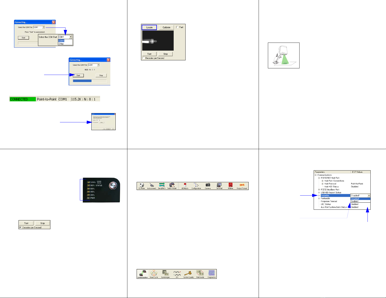
Autoconnect
• Click Start when the Autoconnect dialog appears.
• If your communications port is not the default COM1, use the dropdown
menu to change your port.
When you are connected, you will see the green connection indicator in the
status bar at the bottom right of your screen:
• If the connection attempt fails, click the
Autoconnect
button, select a different
communications port, and try again.
Important: The Imager is in Continuous Read Mode by default. For best
connection results, be sure that no test tubes, caps, or decodable symbols
are within the Imager’s field of view while attempting to connect.
• Once you have
chosen the correct
port, click Start to
connect.
Note: If your RS-232 host settings cannot
be changed to match the imager’s settings,
check the Force Connect box.
Step 9 — Test Read Rate
Read Rate indicates the number of tube/cap detections or successful
decodes per second achieved by the imager.
Test Read Rate by EZ Button
1. To start the Read Rate test, hold down
the EZ Button about three seconds
until you hear three short beeps. The
20%
,
40%
, and
60%
LEDs will illuminate.
While the object is being inspected, the
Read Rate LEDs will indicate the read
rate percentage on the back of the unit.
2. To end the Read Rate test, press the
EZ Button and quickly release.
Test Read Rate by ESP
1. Click the Test button to start the Read Rate test and Stop to end it.
If a tube or cap has been successfully detected, or a symbol has been
successfully decoded, the object’s data and related features will be
presented in the field below the image display window. Also, while the
object is being inspected, the Read Rate LEDs will indicate the Read
Rate percentage on the back of the unit.
2. To end the test, click the Stop button.
Note: Read Rate can also be tested using the Read Rate interface in
Utilities.
Test Read Rate by Serial Command
You can also start a test with the <C> or <Cp> command and end it with the
<J> command.
Step 10 — Configure the Imager
in ESP
To make setup changes to the EZ Match Imager, click the App Mode button.
The following modes are accessible by clicking the buttons in the first row of
App
Mode
icons:
•ClicktheAutoconnect button to establish communications between ESP and
the imager.
• Click the Send/Recv button to send or receive commands.
• Click the EZ Match button to configure Multi-Operation settings, Tube/Cap
Library settings, and Tube/Cap Detection messages.
•
Click the
Camera
button to access a live Video view, Evaluate image captures,
Calibrate the imager, set the Window of Interest, fine-tune capture settings
and
processing settings
in the Configuration Database, and control multiple read
cycle functions in Dynamic Setup.
• Click the Terminal button to display tube or cap detection data or decoded
symbol data, and to send serial commands to the imager using text or macros.
• Click the Utilities button to test Read Rate, request or clear Counters,
enable or disable the imager or send output pulses in Device Control, determine
the Differences from Default in the current settings, add or remove master
symbol data in Master Database, and verify or update the imager’s Firmware.
• Click the Output Format button to determine the order and content of data
output.
Click the Configuration button to display the second row of ESP icons.
From here you can make changes in the tree controls that can be accessed by
clicking the buttons on the second row of icons in the
ESP
window.
For further details, see Microscan ESP Help in the dropdown Help menu.
Step 8 — Calibrate
EZ Match settings can be adjusted automatically for optimum tube/cap
detection and symbol decoding performance by either the EZ Button or by
ESP
.
During the calibration routine, the imager will flash its amber Read Rate
percent LEDs and red illumination LEDs while searching camera settings
and determining the best configuration for detecting tubes or caps, or for
decoding symbol data. Upon successful completion of this routine, a green
LED pattern will flash brightly and illuminate the object. If unsuccessful, the
imager will emit 5 short beeps and stop searching.
Calibrate by EZ Button
1. Hold down the EZ Button for about two seconds and release when you
hear two short beeps. The 20% and 40% LEDs will illuminate.
2.
The imager will search camera settings to determine the best configuration
for detecting tubes or caps, or for decoding symbol data.
Note: To end all EZ Button functions, press the EZ Button once and
quickly release.
Calibrate by ESP
1. Click the Calibrate button.
2.
The imager will search camera settings to determine the best configuration
for detecting tubes or caps, or for decoding symbol data.
A successful calibration will display a green frame around the object,
and the following message will appear: “Uploading all reader parameters.”
Aftera moment the tube/cap data and/or symbol data will be presented
in the field below the image display window.
Calibrate by Serial Command
Send <@CAL> from a terminal program to begin calibration.
Step 11 — Save Changes in ESP
To make changes to a configuration setting:
•Send, No Save. Changes will be lost when power is re-applied to the
imager.
•Send and Save. This activates all changes in current memory and saves
to the imager for power-on.
1. Left click on the
+to expand the
desired tree.
2. Double click on
the desired
parameter and
click once in the
selection box to
view options.
5. Right click on the
open screen and
select Save to
Readertoimplement
the command in the
imager.
4. Left click on the
open screen to
complete your
selection.
3. Place your cursor
in the selection
box, scroll down to
the setting you
want to change,
and click once on
the setting.
Saving Options
Step 7 —
Locate the Object
Locate the Object by ESP
•InESP’s EZ Mode, click the Locate button to enable the blue target pattern.
The object in the field of view will appear in the video view beneath the
Locate
and
Calibrate
buttons, and you will see the blue target
pattern projected
from the front of the imager.
• Center the target pattern on the object.
At 2 to 3 inches, the pattern resembles an X. At 3 to 6 inches, the pattern
resembles a V.
Important: The entire object of interest (tube, cap, or symbol) should fall
within the field of view (FOV) of the imager. The field of view is what appears
in ESP’s Locate/Calibrate window in EZ Mode.
• Click the Stop button to end the Locate function.
Locate the Object by EZ Button
If you are not connected to a host computer, the EZ Button allows you to locate
an object in the imager’s field of view.
• Hold down the EZ Button for about one second and release when you hear
one short beep. The amber 20% LED will illuminate, and you will see the
blue target pattern projected from the front of the imager.
• Center the target pattern on the object.
Note: To end all EZ Button functions, press the EZ Button once and quickly
release.


