manuals.online logo
Brands
  1. Home
  2. •
  3. Brands
  4. •
  5. Graco
  6. •
  7. Control Unit
  8. •
  9. Graco 222-411 Datasheet

Graco 222-411 Datasheet

307–995
Rev. K
Supersedes Rev. J
INSTRUCTIONS-PARTS
LIST
INSTRUCTIONS
This
manual contains important
warnings and information.
READ AND KEEP FOR REFERENCE.
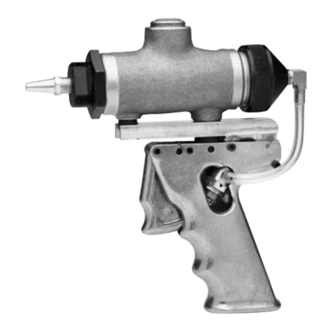
Electronic or Mechanical Lubricant V
alve, Metered or Unmetered
In-Line
Dispense V
alves
1000 psi (70 bar) Maximum Working Pressure (Models 222–451, 222–452, 222–453 only)
1500 psi (103 bar) Maximum Working Pressure (All other models)
FOR USE WITH PETROLEUM-BASED LUBRICANTS ONLY
Models
For use
with the
Without
Meter
WIth Electronic Meter
With Mechanical Meter With Mechanical Meter
with the
following
material
Meter Measuring in
Gallon/Quart/
Pint*
Measuring in
Liters
Measured in Quarts or
Pints
Measures in Liters
Oil 222–411
222–421

222–521

222–451 (quarts)
237–121
Gear Lube
222–412
222–422

236–215

222–522

222–452 (pints)
237–122
A.T.F. 222–413
222–423

222–523

222–453 (quarts)
237–123
*
Meter is factory-set in quarts.

These products contain P/N 235–880, which
is Factory Mutual approved as intrinsically
safe for Class I, Division 1, Groups A,B,C,D.

These products contain P/N 235–900, which is
listed by the Canadian Standards Association
as certified as intrinsically safe for Class I,
Division 1, Groups A,B,C,D.
DISPENSE
V
ALVE
222–648 Without
meter or nozzle
GRACO INC. P.O. BOX 1441
MINNEAPOLIS, MN
55440–1441
COPYRIGHT
1989, GRACO INC.
Graco
Inc. is registered to I.S. EN ISO 9001
MODEL
222–421
MODEL 222–452



MODEL 222–413
 
Table
of Contents
Technical
Data
2.
. . . . . . . . . . . . . . . . . . . . . . . . . . . . . . . .
Graco
Phone Number
2.
. . . . . . . . . . . . . . . . . . . . . . . . . .
Warnings 3
. . . . . . . . . . . . . . . . . . . . . . . . . . . . . . . . . . . . . .
Operation 5
. . . . . . . . . . . . . . . . . . . . . . . . . . . . . . . . . . . . .
Troubleshooting 7
. . . . . . . . . . . . . . . . . . . . . . . . . . . . . . . .
Service 8
. . . . . . . . . . . . . . . . . . . . . . . . . . . . . . . . . . . . . . .
Mechanical Meter 8.
. . . . . . . . . . . . . . . . . . . . . . . . . . .
Strainer 8
. . . . . . . . . . . . . . . . . . . . . . . . . . . . . . . . . . . . .
Electronic Meter 9.
. . . . . . . . . . . . . . . . . . . . . . . . . . . . .
Dispense
V
alve 10.
. . . . . . . . . . . . . . . . . . . . . . . . . . . .
Parts
Lists and Drawings
Valve 10.
. . . . . . . . . . . . . . . . . . . . . . . . . . . . . . . . . . . . .
Unmetered
Dispense V
alves 11.
. . . . . . . . . . . . . . . . .
Mechanical
Metered Dispense V
alves 12.
. . . . . . . . .
Metered
In-Line Dispense V
alves 13.
. . . . . . . . . . . . .
Electronic Meter 14.
. . . . . . . . . . . . . . . . . . . . . . . . . . . .
Graco
W
arranty 16.
. . . . . . . . . . . . . . . . . . . . . . . . . . . . . .
Graco
Phone
Number
TO
PLACE AN ORDER
, contact your Graco distrib
-
utor
, or call this number to identify the distributor
closest to you:
1–800–367–4023 T
oll Free
Technical
Data
Electronic Meter
Flow
range*
0.12 to 12.0 gpm
.
. . . . . . . . . . . . . . . . . . . .
(0.456
to 45.6 lpm)
Maximum operating pressure
1500 psi (103 bar)
.
. . . .
Weight (bare meter)
1.9 lb (0.95 kg)
.
. . . . . . . . . . . . . . .
Units
of measurement
Factory-set in quarts.
.
. . . . . . . .
Display
shows quantity in 0.01 increments
up to 199.99 gallons, quarts, or pints.
T
otalizes in gallons or liters up to 19,999 units.
Inlet and outlet
1/2 npt, non-directional flow
.
. . . . . . . . .
Operating temperature range –4
F to 130
F.
. . . . . .
(–20
C to 55

C)
Storage temperature range
–40
F to 140
F.
. . . . . . .
(–40
C to 60

C)
Battery specifications
Rated discharge current
100 microamps
.
. . . . . . . . .
Rated
capacity
1.0 amp hour
.
. . . . . . . . . . . . . . . . . . . .
Maximum
continuous discharge
current
1.0 milliamp
.
. . . . . . . . . . . . . . . . . . . . . . . . . .
Wetted
parts
aluminum, nickel, bronze,
.
. . . . . . . . . . . . .
stainless
steel #304,
cast ALNICO 8, nitrile rubber
Mechanical Meter
Flow
range*
0.4 to 4 gpm (1.5 to 15 lpm)
.
. . . . . . . . . . .
Maximum
operating pressure
1000 psi (70 bar)
.
. . . . .
Maximum
operating temperature
150F (70
C)
.
. . . .
Accuracy +/–
0.65%
.
. . . . . . . . . . . . . . . . . . . . . . . . . . . . .
Inlet
and outlet
1/2 npt(f).
. . . . . . . . . . . . . . . . . . . . . . . . .
Weight 2.1
lbs (0.945 kg)
.
. . . . . . . . . . . . . . . . . . . . . . . . .
Dispense
V
alve
Recommended
maximum flow*
5.0 gpm
.
. . . . . . . . . . .
(19 lpm)
under normal operating conditions
Maximum operating pressure
1500 psi (103 bar)
.
. . . .
Weight
(without meter)
0.4 lb (0.18 kg)
.
. . . . . . . . . . . . .
Inlet
and outlet
1/2 npt
.
. . . . . . . . . . . . . . . . . . . . . . . . . . .
Wetted
parts
aluminum, carbon steel,
.
. . . . . . . . . . . . . .
music
wire, polyurethane,
stainless steel, nitrile rubber
*
Tested
in No. 10
motor oil. Flow rates vary with fluid
pressure
and viscosity
.
 
EQUIPMENT MISUSE HAZARD
Equipment
misuse can cause the equipment to rupture or malfunction and result in serious injury
.

This equipment is for professional use only
.

Read all instruction manuals, tags, and labels before you operate this equipment.

Use the equipment only for its intended purpose. If you are not sure, call your Graco
representative.

Do not alter or modify this equipment.

Check equipment daily
. Repair or replace worn or damaged parts immediately
.

Do not exceed the maximum working pressure of the lowest rated system component. Refer to
the
T
echnical Data
on page 2 for the maximum working pressure of this component.

Use fluids and solvents which are compatible with the equipment wetted parts. Refer to the
T
echnical Data
section of all equipment manuals. Read the fluid and solvent manufacturer
’s
warnings.

Do not use 1,1,1–trichloroethane, methylene chloride, other halogenated hydrocarbon solvents or
fluids that contain such solvents in pressurized aluminum equipment. Such use could result in a
chemical reaction, with the possibility of explosion.

Do not use hoses to pull equipment.

Route hoses away from traffic areas, sharp edges, moving parts, and hot surfaces. Do not
expose Graco hoses to temperatures above 82

C (180

F) or below –40

C (–40
F).

Do not lift pressurized equipment.

Comply with all applicable local, state, and national fire, electrical, and safety regulations.
WARNING
WARNING
INSTRUCTIONS
4 307-995
INJECTION HAZARD
Spray
from the dispensing valve, leaks, or ruptured components can inject fluid into your body and
cause extremely serious injury
, including the need for amputation. Fluid splashed in the eyes or on
the skin can also cause serious injury
.

Fluid injected into the skin may look like just a cut, but it is a serious injury
.
Get immediate med
-
ical attention.

Do not point the dispensing valve at anyone or at any part of the body
.

Do not put your hand or fingers over the end of the dispensing valve.

Do not stop or deflect leaks with your hand, body
, glove or rag.

Use only extensions and no-drip tips which are designed for use with your dispensing valve.

Do not use a low pressure flexible nozzle with this equipment.

Follow the
Pressure Relief Procedure
on page 7 before you clean, check, or service the equip
-
ment.
T
ighten all fluid connections before you operate the equipment.

Check the hoses, tubes, and couplings daily
. Replace worn or damaged parts immediately
. Do
not repair high pressure couplings; you must replace the entire hose.
WARNING
WARNING
 
Operation
Never operate the meter with the black plastic cov
-
er removed. The cover protects the meter from
damage due to impact. Meters are factory sealed
to keep moisture and dirt out. See the
Service
section before you service the meter
.
CAUTION
T
o prevent line contamination, which can cause
equipment malfunction or damage, flush the lines
before you install this equipment in the system.
CAUTION
To Activate the Digital Display
Press
the
RESET
key pad to clear the meter before
you start a new dispense cycle. This is the best way
to activate the meter
, because it also clears the
quantity of the last dispense cycle.
Y
ou can also activate the digital display by pressing
the
TOT
AL key pad or by running fluid through the me
-
ter
. See Fig. 1.
NOTE:
The digital display of the meter goes blank af
-
ter approximately two minutes of non-use.
Function of TOTAL
When
the digital display is blank, press and release the
TOTAL
key pad to display the quantity of the last dis
-
pense cycle. See Fig. 2.
T
o see the accumulated total of fluid dispensed
through the meter
, press and hold the
TOT
AL
key pad.
The accumulated total is shown in gallons for the gal
-
lon/quart/pint meter
, and in liters for the liter meter
.
The meter can accumulate a running total of up to
19999 gallons or liters dispensed before it returns to
zero.
See Fig. 3.
Function of RESET
Press
the
RESET
key pad to clear the quantity of the
last dispense cycle and return the digital display to all
zeros. See Fig. 1.
To Change the Measurement Units
(gallon/quart/pint
meter only)
The meter is factory-set to dispense in quarts. T
o
change the measurement units, press and hold the
RESET
key pad until the measurement unit on the
right side of the digital display is flashing. Then press
the
TOTAL
key pad until the desired measurement unit
is shown. Release both key pads. See Fig. 4.
T
o be sure the proper amount of fluid is dispensed,
always use the same measurement unit for a par
-
ticular fluid.Units should be changed only by autho
-
rized employees.
CAUTION
For Maximum Dispensing Accuracy
(gallon/quart/pint
meter only)
Set the meter to dispense in pints or quarts when you
dispense 1 gallon or less.
Always press the
RESET
key pad to clear the meter
before a new dispense cycle.
EXAMPLE OF MEASUREMENT UNITS
QTS
PTS
PINTS
QUARTS
GALLONS GAL
GAL
GAL
GRACO
Press RESET to
clear
TOTAL RESET
EXAMPLE OF ACCUMULA
TED T
OTAL
DIGIT
AL DISPLA
Y
Fig. 1
Fig. 2
Fig. 3
QTS
Fig. 4
EXAMPLE OF T
OT
AL FOR
LAST DISPENSE CYCLE
6 307-995
Operation
B
B
Fig. 5
Rotate
knurled sleeve of
coupler (B) clockwise to
open it for dispensing
OIL
GEAR
LUBE
A.T.F
.
Electronic
metered
valve shown
Mechanical metered
valve shown
C



B




B

GEAR
LUBE
WARNING
The electronically metered dispense valves have a
1500 psi (103 bar) Maximum Working Pressure.
The mechanically metered dispense valves have a
1000 psi (70 bar) Maximum Working Pressure.
Never
exceed the maximum working pressure of
the valve you are using or of the lowest rated
component in your system, to reduce the risk of a
serious bodily injury
, including fluid injection.
WARNING
T
o reduce the risk of fluid injection, always grasp
the nozzle housing (B) from the threaded end, not
from the front, when you adjust the nozzle.
T
o dispense from the non-drip nozzle, turn the knurled
sleeve clockwise until it is open. T
rigger the valve.
When the dispense cycle is completed,
release the
trigger and close the nozzle by screwing the knurled
sleeve fully counterclockwise.
Electronic Metered Valves
Press
the
RESET
key pad on the meter to clear it be
-
fore the next dispense cycle. See Fig. 1.
Mechanical Metered Valves
Turn
the reset knob (C)
counterclockwise
back to the
zero stop. See Fig. 5. If the knob cannot be turned
easily
, do not force it. Clean and inspect the meter as
explained on page 8.
CAUTION
Do not attempt to manually advance the mechani
-
cal meter or force the reset knob past the zero
stop. Doing so will damage the meter
’
s gear
mechanism.
 
Troubleshooting
PRESSURIZED EQUIPMENT HAZARD
The equipment stays pressurized until
pressure is manually relieved. T
o
reduce the risk of serious injury from
pressurized fluid, accidental spray from the
dispenser or splashing fluid, follow the
Pressure
Relief Procedure
whenever you:

Are instructed to relieve pressure

Stop dispensing

Check, clean, or service any system equipment

Install or clean fluid nozzles
WARNING Pressure Relief Procedure
1. Turn
of
f the power supply to the pump.
2. T
rigger the valve into a waste container to relieve
pressure.
3.
Open any bleed-type master air valves and fluid
drain valves in the system.
4.
Leave the drain valve open until you have com
-
pleted repairs and are ready to pressurize the sys
-
tem.
Electronic Meter
NOTE: Before
you check or repair the meter
, be sure all other valves, controls, and the pump are operating
properly.
Problem Cause Solution
Digital display does not
activate.
Electronic control is malfunctioning.
Replace the electronic control.
Order Part No. 235–878
for gallons/quarts/pints.
Order Part No. 235–901
for liters.
There is no fluid flow
.
Metering unit is malfunctioning. Replace the metering unit.
Order Part No. 235–873
for gallons/quarts/pints.
Order Part No. 235–904
for liters.
Digital display is dim.
Battery in electronic control is worn.
Replace the electronic control within
approximately one week of when you
notice the dimness.
See the part numbers above.
Dispensing
V
alve
Problem Cause Solution
There
is no fluid flow
.
Strainer is clogged.
Remove and clean strainer
.
Mechanical Meter
Problem Cause Solution
There
is no fluid flow
.
Strainer is clogged.
Remove and clean strainer
.
Meter does not register
.
Loose cap or dirt in chamber
.
Screw cap on tightly with o-ring in
proper position, or clean and
inspect meter
.
8 307-995
Service
Mechanical Meter
1. Relieve
the pressure.
WARNING
T
o reduce the risk of serious injury, when you are
instructed to relieve pressure, always follow the
Pressure Relief Procedure
on page 7.
2.
Remove the meter from the valve. Unscrew the
meter cap (K). Remove the o-ring (J), screen (H),
piston and chamber assembly (G), and the planet
gear (A). See Fig. 6.
3.
Insert a screwdriver into the notch of the chamber
assembly (G) and pry of
f the top chamber (B).
See Fig. 7. Remove all parts.
4.
Clean and blow dry the parts. Examine the outer
surface of the piston and the inner surface of the
chamber for pitting or scoring. If any parts are
worn or damaged, replace the complete chamber
and piston assembly (G).
5.
Hold (E) open end up. Insert (D). Insert (C). Align
slot and bearing of (B) with parts inside (E) and
snap together
. Place gear into (B). Place the pis
-
ton and chamber assembly (G) into the housing
and turn it to be sure the gears mesh. With the
screen (H) and o-ring (J) in place, tighten the cap
(K) firmly into the housing (F).
6.
No other parts are user repairable. If your meter
still does not work, return it to Graco repair
.
Strainer
1.
Relieve the pressure.
2.
Remove the swivel (14) and unscrew the strainer
(A).
3.
Clean the filter in mineral spirits. Be careful not to
damage the strainer element.
4.
Reassemble, and torque the swivel to 19 to 21 ft-lb
(26 to 28 N-m). See Fig. 8.
NOTE:
Also see the parts list on page 10.
G
BCD
E
Fig. 6
J
H
A
F
02219
K
Fig. 7
Pry
of
f chamber top
1
102224
14
6
8
21
5
18
Fig.
8
22
Torque
to
19 to 21 ft-lb
(26 to 28 N-m)
1
1
02182
A
 
Service
Electronic Meter
To
avoid damaging the electronic components of
the control:
Always
use the personal grounding strap
provided with a replacement metering unit
and electronic control when you remove the
cover (1) and while you replace the parts.
This strap protects the electronic compo
-
nents from damage due to electrostatic dis
-
charge.

Do not lay anything on the control.

Be sure the open side of the control faces up
if you lay it down.

Do not twist or force parts. Align parts prop
-
erly as instructed.
CAUTION
WARNING
T
o reduce the risk of a fire, explosion, and serious
burns to the body
, handle and dispose of a used
electronic control (103) properly
.
The electronic control contains a lithium battery
. Do
not short circuit, charge, force over discharge, dis
-
assemble, crush, penetrate, incinerate or heat the
battery to a temperature above 185
F (85
C).
Any misuse or abuse of the battery may cause it to
leak or explode.
1.
Relieve the pressure.
WARNING
T
o reduce the risk of serious injury, when you are
instructed to relieve pressure, always follow the
Pressure Relief Procedure
on page 7.
2.
Attach the disposable grounding wrist strap to your
wrist. Connect the adhesive-backed copper foil at
the other end to any convenient electrical ground,
such as the grounding screw or metal case of a
grounded electrical outlet.
3.
Lift the bottom edge of the black cover (101) away
from the meter (102) and pull the cover of
f.
Remove and discard the screws (106). Lift of
f the
electronic control (103). Remove and discard the
large o-ring (104).
4.
Install a new metering unit (102) and/or electronic
control (103). Install the large o-ring (104) over the
lip on top of the metering unit (102). Align the
notch on the side of the electronic control (103)
with the notch on side of the metering unit (102).
Install the new screws (106) and torque them
oppositely and evenly to 4 to 6 in-lb (0.45 to 0.68
N-m).
5.
Install the cover so the rolled-in edges are parallel
with the inlet fluid passage of the metering unit.
Fig. 9
101
103
102
104
106
DET
AIL A
104
106
02175C
02174C
10 307-995
Service
Valve
NOTE:
The top of the pushrod (12) in the valve handle
(8) fits into a notch in the cam (9), which is part of the
trigger assembly
. This is important when you remove
or install parts.
Valve Handle Repair
1. Relieve
the pressure.
WARNING
T
o reduce the risk of serious injury, when you are
instructed to relieve pressure, always follow the
Pressure Relief Procedure
on page 7.
2.
When you replace any part of the valve handle
assembly
, unscrew the swivel (14) and remove the
parts.
3.
Reference the parts drawing below
, and reas
-
semble the valve. Make sure you install all the
parts correctly
. The top of the pushrod (12) must
rest in the notch of the cam (9).
Trigger Repair
1. Relieve
the pressure.
2.
When you replace the quad ring seal (2) or the
cam (9), remove the valve handle parts first. Then
install the cam and seals before you install the
valve handle parts.
3.
Be sure the notches of the cam (9) fit into the flats
of the trigger (10).
Parts
– V
alve

71
2
9
8
3
10
12
15
4
18
5
21
6
14
Model
222–648
Includes items 1 to 22
22
Torque
to
19 to 21 ft-lb
(26 to 28 N-m)



Closed end of pushrod (12)
towards poppet kit (15)

T
orque to 15 to 25 in-lb (1.7 to 2.8 N-m)

Ref
No. Part No. Description Qty Ref
No. Part No. Description Qty
1 110–637 SCREW
,
10–24
x 3/8”
2
2 110–173 SEAL,
quad
ring
2
3 110–174 SPRING,
extension 1
4 110–175 SPRING, compression 1
5 185–415 STRAINER 1
6 155–500
O-RING, nitrile rubber
1
7 160–172 W
ASHER, plain
2
8 185–222 HANDLE 1
9 185–257 CAM 1
10 185–258 TRIGGER 1
12 185–320 PUSHROD, valve 1
14 202–994 VAL
VE SWIVEL, 1/2” thread
1
15 222–647 POPPET KIT 1
18 185–408 HOUSING, strainer 1
21 110–340
RING, retaining, internal
1
22 111–853 GASKET 1
307-995 11
Parts
– Unmetered Dispense V
alves
2
3
4
1

Model
222–41
1 – For Oil
Ref
No. Part No. Description Qty
1* 222–648 VALVE 1
2 203–265
NOZZLE, oil
1
Model
222–412 – For Gear Lube
Ref
No. Part No. Description Qty
1* 222–648 VALVE 1
3 201–701
NOZZLE, gear lube
1
Model
222–413 – For A.T
.F.
Ref
No. Part No. Description Qty
1* 222–648 VALVE 1
4 203–687 NOZZLE, A.T.F. 1
* See parts on page 10.
12 307-995
Parts
– Mechanical Metered
Dispense V
alves
3
4
1
5 or 7
6
2

Model 222–451 – For Oil
Includes items 1,2,5,6,8
Model 237–121 – For Oil
Includes items 1,2,6,7,8
Ref
No. Part No. Description Qty
1* 222–648 VALVE 1
2 203–265
NOZZLE, oil
1
5 157–779
METER, 16 quart, totalizing
1
6 108–478 ELBOW 1
7 157–958
METER, liter
, totalizing
1
8172–479 TAG, W
arning (not shown)
1
Model
222–452 – For Gear Lube
Includes items 1,3,5,6,8
Model 237–122 – For Gear Lube
Includes items 1,3,6,7,8
Ref
No. Part No. Description Qty
1* 222–648 VALVE 1
3 201–701
NOZZLE, gear lube
1
5 157–771
METER, 8 pint, totalizing
1
6 108–478 ELBOW 1
7 157–958
METER, liter
, totalizing
1
8172–479 TAG, W
arning (not shown)
1
Model
222–453 – For A.T
.F.
Includes items 1,4,5,6,8
Model 237–123 – For A.T
.F.
Includes items 1,4,6,7,8
Ref
No. Part No. Description Qty
1* 222–648 VALVE 1
4 203–687 NOZZLE, A.T.F. 1
5 157–779
METER, 16 quart, totalizing
1
6 108–478 ELBOW 1
7 157–958
METER, liter
, totalizing
1
8172–479 TAG, W
arning (not shown)
1
*
See parts on page 10.

Replacement W
arning tags available for free.
307-995 13
Parts
– Metered In-Line Dispense V
alves
305
306
301
302
303

304
308
307
309
With Gallon/Quart/Pint Meter With Liter Meter
Model
222–421 – For Oil
Ref
No. Part No. Description Qty
301 222–648 VALVE
see page 10
1
302 235–880
METER, gal/qt/pt
see page 14
1
303 158–491 NIPPLE,
1/2” npt
1
304 203–265 NOZZLE,
oil
1
Model
222–422 – For Gear Lube
Ref
No. Part No. Description Qty
301 222–648 VAL
VE
see page 10
1
302 235–880
METER, gal/qt/pt
see page 14
1
303 158–491 NIPPLE,
1/2” npt
1
305 201–701 NOZZLE,
gear lube
1
Model
236–215 – For Gear Lube
Ref
No. Part No. Description Qty
301 222–648 VALVE
see page 10
1
302 235–880
METER, gal/qt/pt
see page 14
1
303 158–491 NIPPLE,
1/2” npt
1
307 156–971 NIPPLE 1
308 201–540 NOZZLE,
Gear Lube
1
309 109–160 HOSE 1
Model
222–423 – For A.T
.F.
Ref
No. Part No. Description Qty
301 222–648 VALVE
see page 10
1
302 235–880
METER, gal/qt/pt
see page 14
1
303 158–491 NIPPLE,
1/2” npt
1
306 203–687 NOZZLE,
A.T
.F. 1
Model
222–521 – For Oil
Ref
No. Part No. Description Qty
301 222–648 VAL
VE
see page 10
1
302 235–900
METER, liter
see page 14
1
303 158–491 NIPPLE,
1/2” npt
1
304 203–265 NOZZLE,
oil
1
Model
222–522 – For Gear Lube
Ref
No. Part No. Description Qty
301 222–648 VAL
VE
see page 10
1
302 235–900
METER, liter
see page 14
1
303 158–491 NIPPLE,
1/2” npt
1
305 201–701 NOZZLE,
gear lube
1
Model
222–523 – For A.T
.F.
Ref
No. Part No. Description Qty
301 222–648 VAL
VE
see page 10
1
302 235–900
METER, liter
see page 14
1
303 158–491 NIPPLE,
1/2” npt
1
306 203–687 NOZZLE,
A.T
.F. 1
14 307-995
Parts
– Electronic Meter
101
103
102
104
106

Manual
Change Summary
The
current revision of this manual contains the
following changes:

A caution about flushing the lines is added to the
Operation
section on page 5.

The electronic meter bezel-mounting bosses
(shown in Fig. 9 on page 9 and in the
Parts
drawing above) are raised by 0.18 in.
Model 235–880, Meter – Gallon/Quart/Pint
Includes replaceable items 101 to 106.
Ref
No. Part No. Description Qty
101 109–118 COVER 1
102 235–873*
METERING UNIT – gal/qt/pt
1
103 235–878* ELECTRONIC CONTROL – 1
gal/qt/pt
104 109–137 O-RING 1
106 112–093 SCREW 6
Model
235–900, Meter – Liter
Includes replaceable items 101 to 106.
Ref
No. Part No. Description Qty
101 109–118 COVER 1
102 235–904* METERING UNIT – liter 1
103 235–901* ELECTRONIC CONTROL – 1
liter
104 109–137 O-RING 1
106 112–093 SCREW 6
*
Replacement screws and o-rings included with items
102 and 103.
WARNING
Use
only genuine Graco replacement parts. The
use of any other parts may impair the intrinsic
safety of this meter. This could result in a failure
which causes serious bodily injury and/or substan
-
tial property damage.
307-995 15
Notes
 
The
Graco Electronic Dispense V
alve
W
arranty and Disclaimers
Graco
warrants all equipment manufactured by it and bearing its name to be free from defects in material and workmanship on the date
of
sale by an authorized Graco distributor to the original purchaser for use. As purchaser
’
s sole remedy for breach of this warranty
,
Graco
will, for a period of
twelve months from the date of sale, repair or replace any part of the equipment proven defective, with the
exception
of defects in the electronic meter control, including the battery
, which will be repaired or replaced for twenty-four months from
the
date of sale. This warranty applies only when the equipment is installed, operated and maintained in accordance with Graco’
s
written
recommendations.
This
warranty does not cover
, and Graco shall not be liable for
, any malfunction, damage or wear caused by faulty installation, misap
-
plication,
abrasion, corrosion, inadequate or improper maintenance, negligence, accident, tampering, or substitution of non-Graco
component
parts. Nor shall Graco be liable for malfunction, damage or wear caused
by the incompatibility with Graco equipment of
structures,
accessories, equipment or materials not supplied by Graco, or the improper design, manufacture, installation, operation or
maintenance
of structures, accessories, equipment or materials not supplied by Graco.
This
warranty is conditioned upon the prepaid return of the equipment claimed to be defective to an authorized Graco distributor for
verification
of the claim. If the claimed defect is verified, Graco
will repair or replace free of charge any defective parts. The equipment
will
be returned to the original purchaser transportation prepaid. If inspection of the equipment does not disclose any defect in material
or
workmanship, repairs will be made at a reasonable charge, which charges may include the costs of parts, labor and transportation.
Disclaimers and Limitations. The terms of this
warranty
constitute purchaser
’
s sole and exclusive remedy and are in lieu of any other
warranties
(express or implied),
including warranty of merchantability or warranty of fitness for a particular purpose
, and of any
non-contractual
liabilities, including product liabilities, based on
negligence or strict liability
. Every form of liability for direct, special or
consequential
damages or loss is expressly excluded and denied. In
no case shall Graco’
s liability exceed the amount of the purchase
price.
Any action for breach of warranty must be brought within two (2) years of the date of sale
.
Equipment
not covered by Graco W
arranty
. Graco makes
no warranty
, and disclaims all implied warranties of merchantability
and
fitness for a particular purpose
, with respect to accessories, equipment,
materials, or components sold but not manufactured
by
Graco
.
These
items sold, but not manufactured by Graco (such as electric motor
, switches, hose, etc.) are subject to the warranty
, if
any, of their manufacturer. Graco will provide purchaser with reasonable assistance in making any claim for breach of these
warranties.
Sales
Offices:
Atlanta, Chicago, Detroit, Los Angeles
Foreign Offices:
Belgium, Canada, England, Korea, Switzerland, France, Germany
, Hong Kong, Japan
GRACO INC. P.O. BOX 1441
MINNEAPOLIS, MN
55440–1441
PRINTED
IN U.S.A. 307–995 May 1989, Revised January 1996

This manual suits for next models

15

Other Graco Control Unit manuals

Graco PD44 Guide

Graco

Graco PD44 Guide

Graco CleanShot 244160 Parts list manual

Graco

Graco CleanShot 244160 Parts list manual

Graco 24U175 Parts list manual

Graco

Graco 24U175 Parts list manual

Graco Therm-O-Flow Series Operation manual

Graco

Graco Therm-O-Flow Series Operation manual

Graco E 208997 Operation manual

Graco

Graco E 208997 Operation manual

Graco CSP Series User manual

Graco

Graco CSP Series User manual

Graco Dispensit 1092 Troubleshooting guide

Graco

Graco Dispensit 1092 Troubleshooting guide

Graco Dispensit 1052 Troubleshooting guide

Graco

Graco Dispensit 1052 Troubleshooting guide

Graco PD44 Manual instruction

Graco

Graco PD44 Manual instruction

Graco 256994 Operation manual

Graco

Graco 256994 Operation manual

Graco Trabon MD Series User manual

Graco

Graco Trabon MD Series User manual

Graco Dyna-Star 25U218 User manual

Graco

Graco Dyna-Star 25U218 User manual

Graco 244920 Operation manual

Graco

Graco 244920 Operation manual

Graco 24W870 Manual

Graco

Graco 24W870 Manual

Graco Therm-O-Flow 25C994 User manual

Graco

Graco Therm-O-Flow 25C994 User manual

Graco 256556 Operation manual

Graco

Graco 256556 Operation manual

Graco 482 Series Operation manual

Graco

Graco 482 Series Operation manual

Graco Series A User manual

Graco

Graco Series A User manual

Graco 236864 User manual

Graco

Graco 236864 User manual

Graco Pro-Shot A Series User manual

Graco

Graco Pro-Shot A Series User manual

Graco Cleanshot 244162 User manual

Graco

Graco Cleanshot 244162 User manual

Graco C Series Datasheet

Graco

Graco C Series Datasheet

Graco PR70 Series Manual

Graco

Graco PR70 Series Manual

Graco 202844 Evenflo User manual

Graco

Graco 202844 Evenflo User manual

Popular Control Unit manuals by other brands

Telit Wireless Solutions SL869T3-I Product user guide

Telit Wireless Solutions

Telit Wireless Solutions SL869T3-I Product user guide

Velleman VMP502 user manual

Velleman

Velleman VMP502 user manual

Doepke Dupline DSM 4M operating instructions

Doepke

Doepke Dupline DSM 4M operating instructions

Polsen VCP-2 product manual

Polsen

Polsen VCP-2 product manual

CYP EASYDCC System Installation and user guide

CYP

CYP EASYDCC System Installation and user guide

elero VarioTec operating instructions

elero

elero VarioTec operating instructions

Pickering 40-529A user manual

Pickering

Pickering 40-529A user manual

CAME 001DC001AC installation manual

CAME

CAME 001DC001AC installation manual

Nibe SMO 05 Installer manual

Nibe

Nibe SMO 05 Installer manual

Allen-Bradley POINT I/O PROFIBUS 1734-APB user manual

Allen-Bradley

Allen-Bradley POINT I/O PROFIBUS 1734-APB user manual

Dantel 46017 Installation & operation manual

Dantel

Dantel 46017 Installation & operation manual

Lenz Digital plus LW130 manual

Lenz

Lenz Digital plus LW130 manual

SMC Corporation VT315 Operation manual

SMC Corporation

SMC Corporation VT315 Operation manual

Beninca RI.15K operating instructions

Beninca

Beninca RI.15K operating instructions

Broan VAUTOW Installation and user guide

Broan

Broan VAUTOW Installation and user guide

Trinamic TMCM-351 manual

Trinamic

Trinamic TMCM-351 manual

Lutron Electronics LQR-WPM-6D Installation and operation guide

Lutron Electronics

Lutron Electronics LQR-WPM-6D Installation and operation guide

Azbil CV3000 Series user manual

Azbil

Azbil CV3000 Series user manual

manuals.online logo
manuals.online logoBrands
  • About & Mission
  • Contact us
  • Privacy Policy
  • Terms and Conditions

Copyright 2025 Manuals.Online. All Rights Reserved.