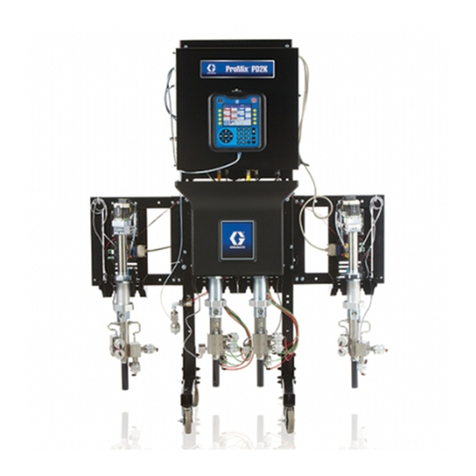
Graco PrecisionFlo 233678 Operation manual
Other Graco Control Unit manuals
Graco
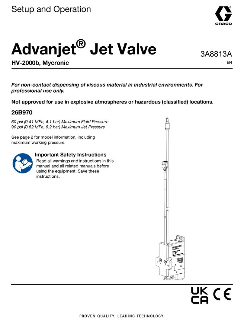
Graco Advanjet 26B970 Manual instruction
Graco
Graco L20c Parts list manual

Graco
Graco 256653 User manual
Graco
Graco 571169 User manual
Graco
Graco 207861 User manual

Graco
Graco Therm-O-Flow 194485 Operation manual
Graco
Graco 15X303 Technical reference manual

Graco
Graco EnDure User manual
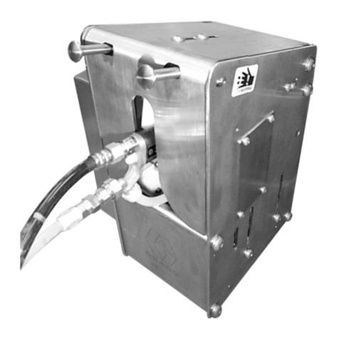
Graco
Graco Gun Flush Box 244105 Operation manual

Graco
Graco Series A User manual
Graco
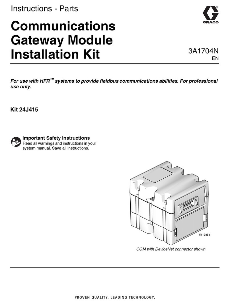
Graco 24J415 Parts list manual

Graco
Graco M5 User manual
Graco
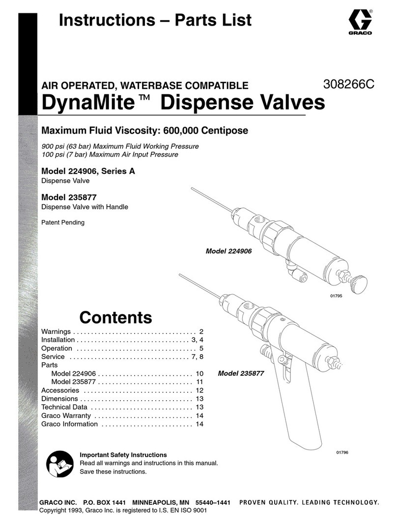
Graco DynaMite 224906 Operation manual

Graco
Graco LDP5 User manual

Graco
Graco 77X542 User manual

Graco
Graco Trabon MD Series User manual
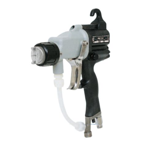
Graco
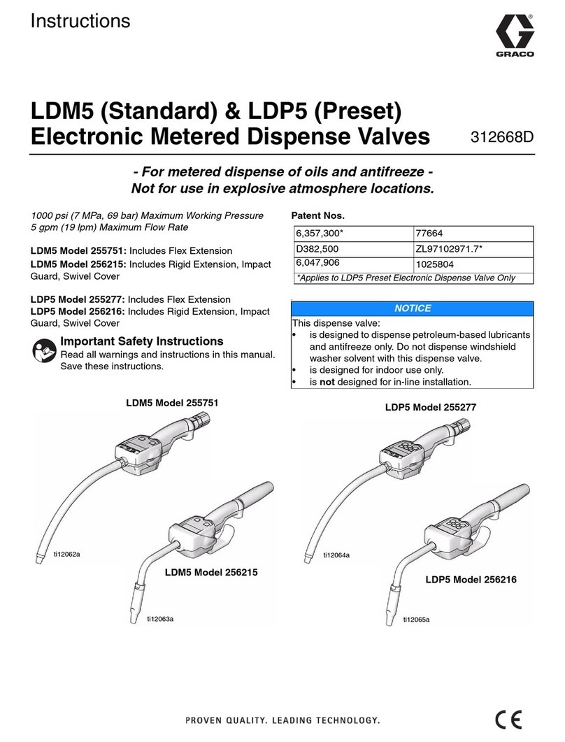
Graco 244912 Operation manual
Graco
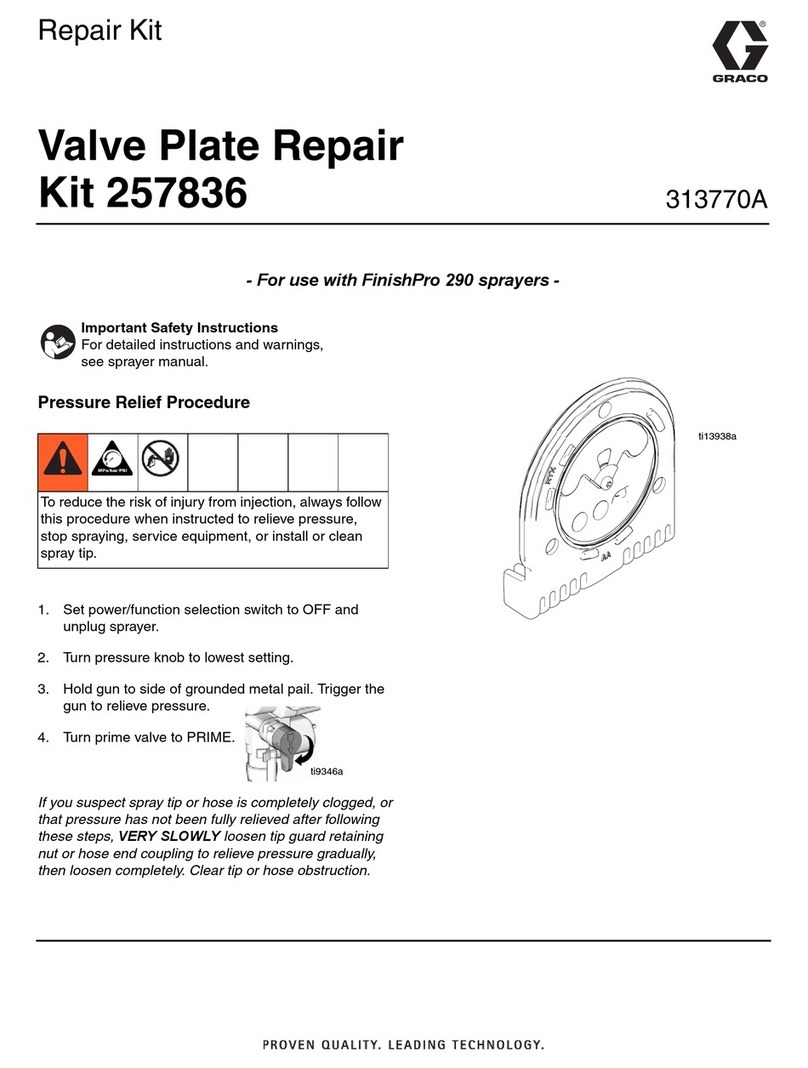
Graco 255751 User manual
Graco
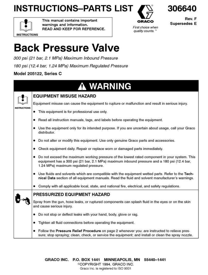
Graco 257836 User manual
Graco
Graco C Series Datasheet
Popular Control Unit manuals by other brands

Festo
Festo Compact Performance CP-FB6-E Brief description

Elo TouchSystems
Elo TouchSystems DMS-SA19P-EXTME Quick installation guide

JS Automation
JS Automation MPC3034A user manual

JAUDT
JAUDT SW GII 6406 Series Translation of the original operating instructions

Spektrum
Spektrum Air Module System manual

BOC Edwards
BOC Edwards Q Series instruction manual

KHADAS
KHADAS BT Magic quick start

Etherma
Etherma eNEXHO-IL Assembly and operating instructions

PMFoundations
PMFoundations Attenuverter Assembly guide

GEA
GEA VARIVENT Operating instruction

Walther Systemtechnik
Walther Systemtechnik VMS-05 Assembly instructions

Altronix
Altronix LINQ8PD Installation and programming manual
