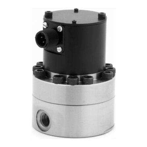
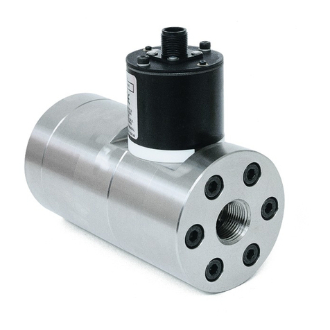
Graco PSM User manual

3A7273B
EN
Instructions
PSM
1K Precision Metering System
For accurate metering and dispensing of single-component materials. For professional
use only.
Not approved for use in explosive atmospheres or hazardous (classified) locations.
100 psi (0.7 MPa, 7 bar) Maximum Air Inlet Pressure.
See page 3 for model information, including maximum fluid working pressure and approvals.
Important Safety Instructions
Read all warnings and instructions in
this manual before using the equipment.
Save these instructions.
PSM Machine,
25 cc, Supply
Pump Feed, IQ
Dispense Valve
Direct Show
PSM Machine,
50 cc, Supply
Pump Feed, IQ
Dispense Valve
Direct Show
PSM Machine,
100 cc, Supply
Pump Feed, IQ
Dispense Valve
Direct Show
PSM Control Box

2 3A7273B
Contents
Related Manuals . . . . . . . . . . . . . . . . . . . . . . . . . . . . 2
Models . . . . . . . . . . . . . . . . . . . . . . . . . . . . . . . . . . . . 3
Warnings . . . . . . . . . . . . . . . . . . . . . . . . . . . . . . . . . . 4
Changing Materials . . . . . . . . . . . . . . . . . . . . . . . 6
Typical Installation . . . . . . . . . . . . . . . . . . . . . . . . . . 7
Component Identification . . . . . . . . . . . . . . . . . . . . 8
PSM Machine, Supply Pump Feed . . . . . . . . . . . 8
PSM Control Box . . . . . . . . . . . . . . . . . . . . . . . . . 9
General Information . . . . . . . . . . . . . . . . . . . . . . . . 10
Installation. . . . . . . . . . . . . . . . . . . . . . . . . . . . . . . . 10
Unpacking . . . . . . . . . . . . . . . . . . . . . . . . . . . . . 10
Locate and Install. . . . . . . . . . . . . . . . . . . . . . . . 11
Grounding . . . . . . . . . . . . . . . . . . . . . . . . . . . . . 13
Power Requirements . . . . . . . . . . . . . . . . . . . . . 13
System Connections . . . . . . . . . . . . . . . . . . . . . 14
Flush Before Using Equipment . . . . . . . . . . . . . 14
HMI Display Operation and Identification . . . . . . 15
Screen Navigation Diagrams . . . . . . . . . . . . . . . 15
Automatic Screen 1 - Main . . . . . . . . . . . . . . . . 19
Automatic Screen 2 - Main . . . . . . . . . . . . . . . . 21
Automatic Screen 3 - Main . . . . . . . . . . . . . . . . 23
Automatic Screen 4 - Maintenance record . . . . 24
Automatic Screen 5 - Job history . . . . . . . . . . . 24
Automatic Screen 6 - Error history . . . . . . . . . . 25
System Main Screen . . . . . . . . . . . . . . . . . . . . . 25
Manual Screen 1 . . . . . . . . . . . . . . . . . . . . . . . . 26
Manual Screen 2 . . . . . . . . . . . . . . . . . . . . . . . . 27
Setup Screen . . . . . . . . . . . . . . . . . . . . . . . . . . . 27
Advanced Screen. . . . . . . . . . . . . . . . . . . . . . . . 36
Operation. . . . . . . . . . . . . . . . . . . . . . . . . . . . . . . . . 38
Startup . . . . . . . . . . . . . . . . . . . . . . . . . . . . . . . . 38
Prime the System. . . . . . . . . . . . . . . . . . . . . . . . 39
Weight Check. . . . . . . . . . . . . . . . . . . . . . . . . . . 40
Shutdown. . . . . . . . . . . . . . . . . . . . . . . . . . . . . . 40
Pressure Relief Procedure . . . . . . . . . . . . . . . . . 41
Flush the Equipment . . . . . . . . . . . . . . . . . . . . . 42
Maintenance . . . . . . . . . . . . . . . . . . . . . . . . . . . . . . 43
Preventive Maintenance. . . . . . . . . . . . . . . . . . . 43
Recycling and Disposal . . . . . . . . . . . . . . . . . . . . . 44
End of Product Life . . . . . . . . . . . . . . . . . . . . . . 44
Troubleshooting . . . . . . . . . . . . . . . . . . . . . . . . . . . 45
Dimensions . . . . . . . . . . . . . . . . . . . . . . . . . . . . . . . 48
PSM Machine, Supply Pump Feed, 25 cc . . . . . 48
PSM Machine, Supply Pump Feed, 50 cc . . . . . 49
PSM Machine, Supply Pump Feed, 100 cc . . . . 50
PSM Control Box . . . . . . . . . . . . . . . . . . . . . . . . 51
Appendix A - PSM Error Codes . . . . . . . . . . . . . . . 52
Schematics . . . . . . . . . . . . . . . . . . . . . . . . . . . . . . . 56
I/O signals . . . . . . . . . . . . . . . . . . . . . . . . . . . . . 58
Timing Chart. . . . . . . . . . . . . . . . . . . . . . . . . . . . 60
Technical Specifications . . . . . . . . . . . . . . . . . . . . 64
California Proposition 65 . . . . . . . . . . . . . . . . . . . . 65
Graco Standard Warranty. . . . . . . . . . . . . . . . . . . . 66
Related Manuals
Manuals
in English Description
3A9277 PSM Repair and Parts Manual
308876 1K Ultra-LiteTM Instructions and Parts List
Manual
333585 IQ Dispense Valves Instructions and Parts
List Manual


Models
3A7273B 3
Models
(1) SST: Stainless steel material
(2) CER: Ceramic material
(3) Any PSM system can be converted from
direct connection mode to remote
connection mode by using remote kits. See
Remote Kits in your PSM Repair-Parts
Manual and order remote kits. See Related
Manuals, page 2.
Part
Maximum Fluid
Working Pressure
psi (MPa, bar) Description
Includes:
PSM
Machine
PSM
Control
Box
Direct
Connection(3)
25S141
1200 psi (8.3 MPa,
83 bar)
PSM System, 25 cc, I/O, SST(1) ✓ ✓ ✓
25S148 PSM System, 25 cc, I/O, CER(2) ✓ ✓ ✓
2000828 PSM System, 25 cc, I/O, SST(1), Tip Seal ✓ ✓ ✓
2000829 PSM System, 25 cc, I/O, CER(2), Tip Seal ✓ ✓ ✓
2001633 PSM System, 25 cc, I/O, SST(1), Ball Seal ✓ ✓ ✓
2001634 PSM System, 25 cc, I/O, CER(2), Ball Seal ✓ ✓ ✓
25S142
3000 psi (20.7
MPa, 207 bar)
PSM System, 50 cc, I/O, SST(1) ✓ ✓ ✓
25S167 PSM System, 50 cc, I/O, CER(2) ✓ ✓ ✓
2000830 PSM System, 50 cc, I/O, SST(1), Tip Seal ✓ ✓ ✓
2000831 PSM System, 50 cc, I/O, CER(2), Tip Seal ✓ ✓ ✓
2001635 PSM System, 50 cc, I/O, SST(1), Ball Seal ✓ ✓ ✓
2001636 PSM System, 50 cc, I/O, CER(2), Ball Seal ✓ ✓ ✓
25S143
3000 psi (20.7
MPa, 207 bar)
PSM System, 100 cc, I/O, SST(1) ✓ ✓ ✓
25S170 PSM System, 100 cc, I/O, CER(2) ✓ ✓ ✓
2000832 PSM System, 100 cc, I/O, SST(1), Tip Seal ✓ ✓ ✓
2000833 PSM System, 100 cc, I/O, CER(2), Tip Seal ✓ ✓ ✓
2001637 PSM System, 100 cc, I/O, SST(1), Ball Seal ✓ ✓ ✓
2001638 PSM System, 100 cc, I/O, CER(2), Ball Seal ✓ ✓ ✓

Warnings
4 3A7273B
Warnings
The following warnings are for the setup, use, grounding, maintenance, and repair of this equipment. The
exclamation point symbol alerts you to a general warning and the hazard symbols refer to procedure-specific risks.
When these symbols appear in the body of this manual or on warning labels, refer back to these Warnings.
Product-specific hazard symbols and warnings not covered in this section may appear throughout the body of this
manual where applicable.
WARNING
ELECTRIC SHOCK HAZARD
This equipment must be grounded. Improper grounding, setup, or usage of the system can cause
electric shock.
• Turn off and disconnect power at main switch before disconnecting any cables and before servicing
or installing equipment.
• Connect only to grounded power source.
• All electrical wiring must be done by a qualified electrician and comply with all local codes and
regulations.
SKIN INJECTION HAZARD
High-pressure fluid from dispensing device, hose leaks, or ruptured components will pierce skin. This
may look like just a cut, but it is a serious injury that can result in amputation. Get immediate surgical
treatment.
• Do not point dispensing device at anyone or at any part of the body.
• Do not put your hand over the fluid outlet.
• Do not stop or deflect leaks with your hand, body, glove, or rag.
• Follow the Pressure Relief Procedure when you stop dispensing and before cleaning, checking, or
servicing equipment.
• Tighten all fluid connections before operating the equipment.
• Check hoses and couplings daily. Replace worn or damaged parts immediately.
TOXIC FLUID OR FUMES HAZARD
Toxic fluids or fumes can cause serious injury or death if splashed in the eyes or on skin, inhaled, or
swallowed.
• Read Safety Data Sheets (SDSs) to know the specific hazards of the fluids you are using.
• Store hazardous fluid in approved containers, and dispose of it according to applicable guidelines.
PERSONAL PROTECTIVE EQUIPMENT
Wear appropriate protective equipment when in the work area to help prevent serious injury, including
eye injury, hearing loss, inhalation of toxic fumes, and burns. Protective equipment includes but is not
limited to:
• Protective eyewear, and hearing protection.
• Respirators, protective clothing, and gloves as recommended by the fluid and solvent manufacturer.

Warnings
3A7273B 5
FIRE AND EXPLOSION HAZARD
Flammable fumes, such as solvent and paint fumes, in work area can ignite or explode. Paint or
solvent flowing through the equipment can cause static sparking. To help prevent fire and explosion:
• Use equipment only in well-ventilated area.
• Eliminate all ignition sources; such as pilot lights, cigarettes, portable electric lamps, and plastic
drop cloths (potential static sparking).
• Ground all equipment in the work area. See Grounding instructions.
• Never spray or flush solvent at high pressure.
• Keep work area free of debris, including solvent, rags and gasoline.
• Do not plug or unplug power cords, or turn power or light switches on or off when flammable fumes
are present.
• Use only grounded hoses.
• Hold gun firmly to side of grounded pail when triggering into pail. Do not use pail liners unless they
are anti-static or conductive.
•Stop operation immediately if static sparking occurs or you feel a shock. Do not use equipment
until you identify and correct the problem.
• Keep a working fire extinguisher in the work area.
EQUIPMENT MISUSE HAZARD
Misuse can cause death or serious injury.
• Do not operate the unit when fatigued or under the influence of drugs or alcohol.
• Do not exceed the maximum working pressure or temperature rating of the lowest rated system
component. See Technical Specifications in all equipment manuals.
• Use fluids and solvents that are compatible with equipment wetted parts. See Technical
Specifications in all equipment manuals. Read fluid and solvent manufacturer’s warnings. For
complete information about your material, request Safety Data Sheets (SDSs) from distributor or
retailer.
• Turn off all equipment and follow the Pressure Relief Procedure when equipment is not in use.
• Check equipment daily. Repair or replace worn or damaged parts immediately with genuine
manufacturer’s replacement parts only.
• Do not alter or modify equipment. Alterations or modifications may void agency approvals and
create safety hazards.
• Make sure all equipment is rated and approved for the environment in which you are using it.
• Use equipment only for its intended purpose. Call your distributor for information.
• Route hoses and cables away from traffic areas, sharp edges, moving parts, and hot surfaces.
• Do not kink or over bend hoses or use hoses to pull equipment.
• Keep children and animals away from work area.
• Comply with all applicable safety regulations.
MOVING PARTS HAZARD
Moving parts can pinch, cut or amputate fingers and other body parts.
• Keep clear of moving parts.
• Do not operate equipment with protective guards or covers removed.
• Equipment can start without warning. Before checking, moving, or servicing equipment, follow the
Pressure Relief Procedure and disconnect all power sources.
WARNING

Warnings
6 3A7273B
Changing Materials
NOTICE
Changing the material types used in your equipment
requires special attention to avoid equipment damage
and downtime.
• When changing materials, flush the equipment
multiple times to ensure it is thoroughly clean.
• Always clean the fluid inlet strainers after flushing.
• Check with your material manufacturer for
chemical compatibility.
• When changing between epoxies and urethanes
or polyureas, disassemble and clean all fluid
components and change hoses. Epoxies often
have amines on the B (hardener) side. Polyureas
often have amines on the B (resin) side.

Typical Installation
3A7273B 7
Typical Installation
Key:
A Main Air Line
B Air Filter (1)
C Pressure Regulator Valve (1)
D Bleed-type Master Air Valve (1)
E Supply Pump System
F PSM Control Box
G Customer Robot
H PSM Machine
J Customer Robot Control Box
K Air Line of Supply Pump
L Material Supply Line
M Air Line of PSM
N Servo Motor Encoder Cable
P Servo Motor Power Cable
R Junction Box Communication Cable
S I/O Communication Cable
(1) Required, but not supplied
FIG. 1: Typical Installation
A
E
G
DC
B
R
P
N
M
L
K
J
H
S
F
Main Power

Component Identification
8 3A7273B
Component Identification
PSM Machine, Supply Pump Feed
Key:
AA Junction Box Assembly
AB Dispense Valve
AC Installation Plate
AD Reload Valve
AE Drive Assembly
AF Base Unit
AG Piston observation hole (1)
(1)The sketch takes 25 cc as an example. The piston
observation holes for 50 cc and 100 cc are at the
same places.
FIG. 2: PSM Machine, Supply Pump Feed
AB
AC
AA
AE
AD
AB
AC
AA
AE
AD
AB
AC
AA
AE
AD
AF
AF
AF
AG
25 cc
100 cc
50 cc

Component Identification
3A7273B 9
PSM Control Box
Key:
BA Human Machine Interface (HMI) Display
BB Control Power On/Off Buttons
BC Emergency Stop Switch
BD Main Power Switch
BE Connection Plate
FIG. 3: PSM Control Box
BA
BC
BB
BD
BE
Front View Left View Bottom View

General Information
10 3A7273B
General Information
FIG. 1, FIG. 2 and FIG. 3 are only a guide for identifying
system components and for assisting in installation.
Contact your Graco distributor or Graco China
Customer Service for assistance in designing a system
to suit your specific needs.
Installation
Unpacking
1. Inspect the shipping container carefully for
damage. Contact the carrier promptly if there is
damage.
2. Open the box and inspect the contents carefully.
There should not be any loose or damaged parts in
the container.
3. Compare the packing slip against all the items in
the box. Report any shortage or other inspection
problems immediately.
4. Remove the PSM system components from the
container.
All electrical wiring must be done by a qualified
electrician and comply with all local codes and
regulations.

General Information
3A7273B 11
Locate and Install
1. The PSM Machine (H, page 7) can be directly
mounted on a Customer Robot (G, page 7) or
remotely mounted on a motion table. Verify the
location has access to compressed air and AC
power.
2. Place the PSM Machine (H, page 7) onto the
designated location.
3. Attach the PSM Installation Plate (AC, page 8) to
the selected location by installing fasteners (not
provided with the PSM machine) through the four
mounting holes. There are also two position pin
holes. Refer to FIG. 4, FIG. 5 or FIG. 6 for mounting
hole dimensions.
FIG. 4: Mounting Hole Dimensions for Installing the PSM Machine - 25cc
FIG. 5: Mounting Hole Dimensions for Installing the PSM Machine - 50cc
2.756 in.
(70 mm)
5.512 in.
(140 mm)
3.190 in.
(81 mm)
3.190 in.
(81 mm)
2 x Ø0.315 in. (8.0 mm) Through
4 x Ø0.335 in. (8.5 mm) Through
2.756 in.
(70 mm)
3.740 in.
(95 mm)
3.583 in.
(91 mm)
3.583 in.
(91 mm)
2 x Ø0.315 in. (8.0 mm) Through
4 x Ø0.335 in. (8.5 mm) Through

General Information
12 3A7273B
FIG. 6: Mounting Hole Dimensions for Installing the PSM Machine - 100cc
2.756 in.
(70 mm)
3.583 in.
(91 mm)
2 x Ø0.315 in. (8.0 mm) Through
4 x Ø0.335 in. (8.5 mm) Through
3.583 in.
(91 mm)
4.921 in.
(125 mm)

General Information
3A7273B 13
Grounding
PSM Machine (H, page 7): grounded through the PSM
Installation Plate (AC, page 8). Use the supplied ground
wire and clamp to ground the metal PSM Installation
Plate (AC, page 8) or Customer Robot (G, page 7) to a
true earth ground.
PSM Control Box (F, page 7): grounded through the
power cord.
Air and fluid hoses: use only electrically conductive
hoses with a maximum of 500 ft. (150 m) combined
hose length to ensure grounding continuity. Check
electrical resistance of hoses. If total resistance to
ground exceeds 29 megohms, replace hose
immediately.
Air compressor: follow manufacturer’s
recommendations.
Dispense Valve (AB, page 8): ground through
connection to a properly grounded fluid hose and
pump.
Fluid supply container: follow local code.
Solvent pails used when flushing: follow local code.
Use only conductive metal pails, placed on a grounded
surface. Do not place the pail on a non-conductive
surface, such as paper or cardboard, which interrupts
grounding continuity.
Power Requirements
The system requires a dedicated circuit protected with
a circuit breaker.
The equipment must be grounded to reduce the risk
of static sparking and electric shock. Electric or static
sparking can cause fumes to ignite or explode.
Improper grounding can cause electric shock.
Grounding provides an escape wire for the electric
current.
FIG. 7 Grounding
Voltage Phase Hz Current
200-240 VAC 1 50/60 10 A

General Information
14 3A7273B
System Connections 1. Connect the PSM System Air Line (M, page 7) to
the air inlet of Junction Box Assembly (AA, page 8).
The maximum air pressure is 100 psi (0.7 MPa, 7
bar). The air flow is over 1 CFM.
2. Connect the Material Supply Lines (L, page 7) to the
corresponding material inlet at the top of Reload
Valve (AD, page 8).
3. Using the power cord provided, connect AC power
(220 V, 50/60 Hz, single phase) to the Power
Connection (BL, page 9) on the back of PSM
Control Box (F, page 7).
4. Follow the marks on PSM Control Box (H, page 7)
and marks on cables to connect junction box, servo
motor power and servo motor encoder from the
PSM Machine (H, page 7) to PSM Control Box (F,
page 7).
Flush Before Using Equipment
The equipment was tested with lightweight oil, which is
left in the fluid passages to protect parts. To avoid
contaminating your fluid with oil, flush the equipment
with a compatible solvent before using the equipment.
Follow Flush the Equipment on page 42.
All electrical wiring must be done by a qualified
electrician and comply with all local codes and
regulations.
This equipment stays pressurized until pressure is
manually relieved. To help prevent serious injury from
pressurized fluid, such as skin injection and
splashing, keep fingers and other body parts away
from the spray tip.
To avoid injury from toxic fluids or fumes, such as
splashing in the eyes or on skin, wear appropriate
personal protective equipment.
FIG. 8: Cable Connections - Supply Pump Feed Version
Junction Box
Cable
Servo Motor
Encoder Cable
Servo Motor
Power Cable
Material Inlet

HMI Display Operation and Identification
3A7273B 15
HMI Display Operation and Identification
Screen Navigation Diagrams
NOTE: The interaction among screens can be achieved by selecting the icons on the screen. The following
diagrams take icons as example.
Automatic Screen 1 - Main
(see page 19)
Automatic Screen 1 - Main
(see page 19)
See next page
Automatic Screen 2 - Main
(see page 21)
Automatic Screen 6 - Error history
(see page 25)
Automatic Screen 5 - Job history
(see page 24)
Automatic Screen 3 - Main
(see page 23)
Automatic Screen 4 - Maintenance record
(see page 24)

HMI Display Operation and Identification
16 3A7273B
Continued
See next page
Automatic Screen 1 - Main
(see page 19)
Pressure monitoring
(see page 20)
Manual Screen 2
(see page 27)
Manual Screen 1
(see page 26)
System Main Screen
(see page 25)
Advanced Screen
(see page 36)
Enter 1492 in
‘Password’
and select
‘Advanced’.

HMI Display Operation and Identification
3A7273B 17
Continued
System Main Screen
(see page 25)
Setup Screen 1 - Reload
(see page 27)
Setup Screen 4 - Sequence
(see page 30)
Setup Screen 5 - Style
(see page 30)
Setup Screen 6 - Purge
(see page 31)
Setup Screen 7 - Pre-charge
(see page 32)
Setup Screen 3 - Bead
(see page 29)
Setup Screen 2 - Shot
(see page 29)
NOTE: Click the button in any screen that has the button can display the System Main Screen, which is not
showed in the following diagrams.
Advanced Setup Screen - 1
(see page 34)
Setup Screen 8 - Depressurize
(see page 33)
See next page

HMI Display Operation and Identification
18 3A7273B
Setup Screen 8 - Depressurize
(see page 33)
Setup Screen 1 - Reload
(see page 27)
Advanced Setup Screen - 2
(see page 35)
Advanced Setup Screen - 1
(see page 34)
Advanced Setup Screen - 3
(see page 35)
Continued

HMI Display Operation and Identification
3A7273B 19
Automatic Screen 1 - Main
Open the control box and wait for some time. The
system will display ‘Automatic Screen 1 - Main’.
The content and functions of this screen are as follows:
• : Select to display the System Main Screen.
This button is only available when the system is in
standby or has an alarm. When on the System Main
Screen, the system will not work in automation
mode.
• : Select to display Automatic Screen 4 -
Maintenance record.
• : Select to execute the command of returning
to home point. The system must be inactive when
the ‘HOME’ button is selected. Check in the
information bar to see if the piston has returned to
the home point.
• : Select to display Automatic Screen 5 - Job
history.
• : Select to display Automatic Screen 2 - Main.
• : Select to display Automatic Screen 6 - Error
history.
Information bar
• To illustrate the current status of equipment, such
as Auto-Standby or Auto-Shot dispense.
• To show error information when an alarm is active.
Status bar
•Job style: To show the current style number which
defined on Setup Screen 5 - Style, see page 30.
•Job target: To show the target volume which
defined on Setup Screen 5 - Style, see page 30.
•Job time: To show the accumulative time of a job.
•Job volume: To show the accumulative volume of
a job.
FIG. 9 Automatic Screen 1 - Main

HMI Display Operation and Identification
20 3A7273B
Pressure monitoring
The current pressure is shown in psi. The operator can
change the unit of pressure. See Pressure unit,
page 34. Click to see working pressure trend.
On Pressure Monitoring Screen, select to display
Automatic Screen 1 - Main.
Progress bar and dispense volume
•Progress bar
- Shot mode: The progress bar displays the
completion of the current target.
- Bead mode: The progress bar always displays
100%.
•Dispense volume: Display the volume for current
one shot.
Volume in cylinder
This displays how much material is in the cylinders
(0-100%). When the rod slider is at the home position,
‘Volume in cylinder’ will show 100%. When the slider
moves to the ‘empty’ position, ‘Volume in cylinder’ will
show 0%.
‘Reset’ button
When the system sends out the alarm, select the button
to stop the alarm.
Table of contents
Other Graco Measuring Instrument manuals

Graco
Graco Series B User manual

Graco
Graco Magnum Project Painter 5 User manual

Graco
Graco 121325 Operation manual

Graco
Graco PD44 User manual

Graco
Graco 244023 Datasheet

Graco
Graco XDI12 User manual

Graco
Graco ProControl 1KE Parts list manual

Graco
Graco 215474 User manual

Graco
Graco PGM Parts list manual

Graco
Graco EM5 Series User manual

Graco
Graco 244075 User manual

Graco
Graco ProMix 2KE Use and care manual

Graco
Graco PPM 3050H Operation manual

Graco
Graco Pulse TLM Operation manual

Graco
Graco G3000 User manual

Graco
Graco HORIZON Operation manual

Graco
Graco IM20P Datasheet

Graco
Graco IM5 Datasheet

Graco
Graco PM8 User manual

Graco
Graco 234576 Operation manual