manuals.online logo
Brands
  1. Home
  2. •
  3. Brands
  4. •
  5. Graco
  6. •
  7. Paint Sprayer
  8. •
  9. Graco 232833 User manual

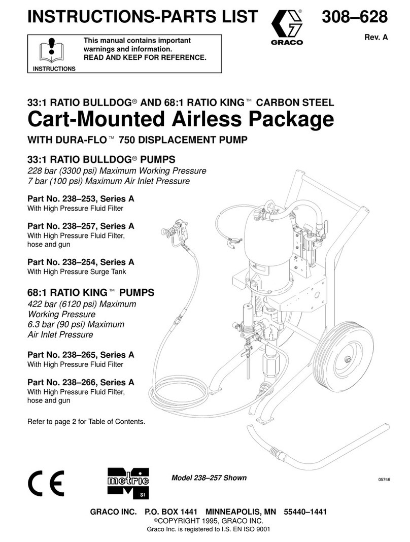
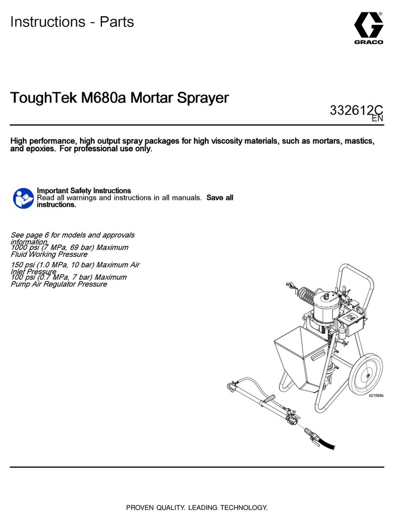
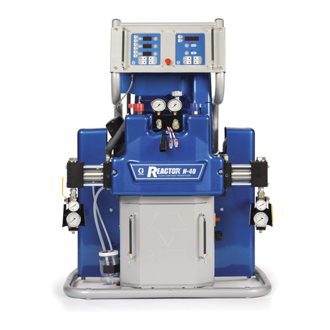
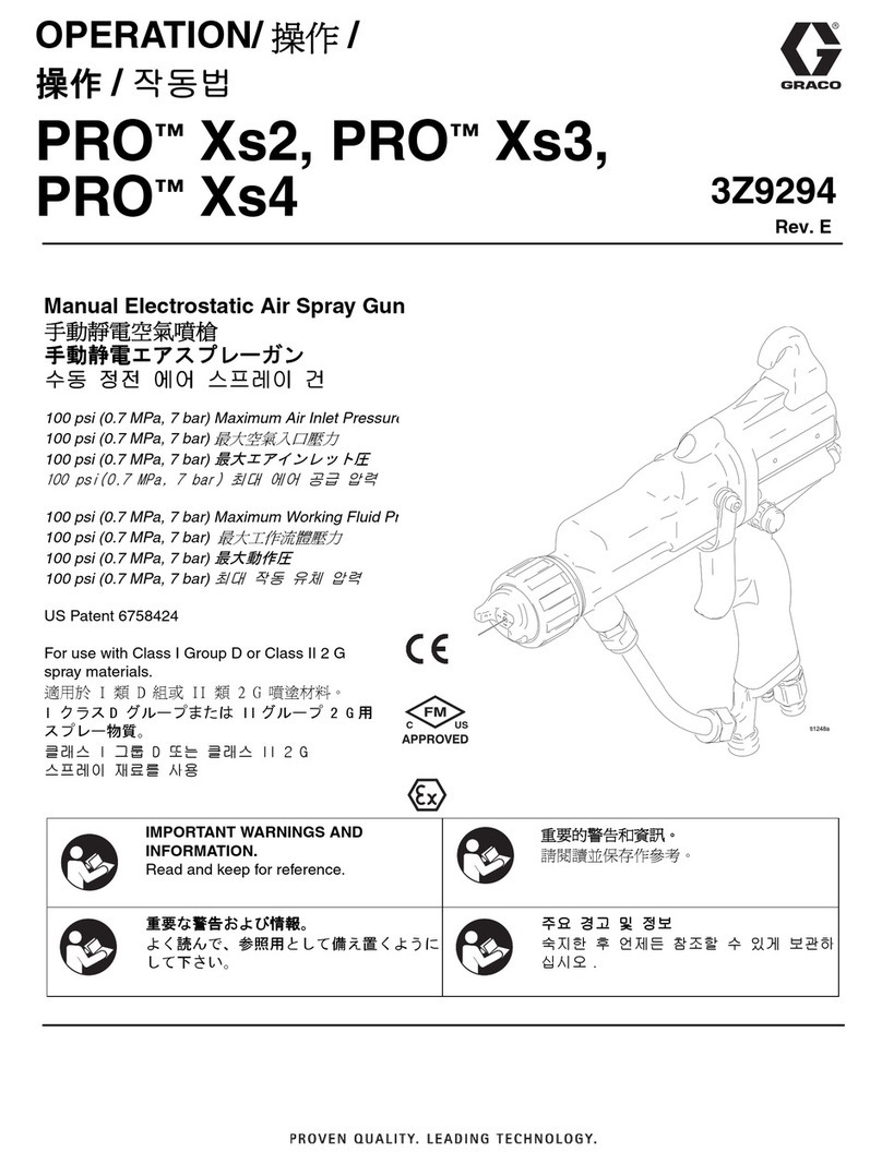
Graco 232833 User manual

Instructions – Parts List
GRACO INC. P.O. BOX 1441 MINNEAPOLIS, MN 55440–1441
Copyright 1999, Graco Inc. is registered to I.S. EN ISO 9001
Falcon and Falcon II
Air-Assisted Euro Packages
309022 rev.E
9344B
Model 232833 Shown
Important Safety Instructions
Read all warnings and instructions in this manual.
Save these instructions.
Parts
2 309022
Table of Contents
List of Models 2. . . . . . . . . . . . . . . . . . . . . . . . . . . . . . . . . .
Warnings 3. . . . . . . . . . . . . . . . . . . . . . . . . . . . . . . . . . . . . .
Installation 6. . . . . . . . . . . . . . . . . . . . . . . . . . . . . . . . . . . . .
Operation 10. . . . . . . . . . . . . . . . . . . . . . . . . . . . . . . . . . . .
Maintenance 14. . . . . . . . . . . . . . . . . . . . . . . . . . . . . . . . . .
Parts 16. . . . . . . . . . . . . . . . . . . . . . . . . . . . . . . . . . . . . . . .
Technical Data 20. . . . . . . . . . . . . . . . . . . . . . . . . . . . . . . .
Dimensions 22. . . . . . . . . . . . . . . . . . . . . . . . . . . . . . . . . . .
Graco Warranty 24. . . . . . . . . . . . . . . . . . . . . . . . . . . . . . .
Graco Information 24. . . . . . . . . . . . . . . . . . . . . . . . . . . . .
List of Models
Package
Part No. Series Pump Model
Maximum Fluid
Working Pressure
Maximum Air
Input Pressure
Gun Ball/
Seat Material
232833 C Falcon 10:1 1000 psi (6.9 MPa, 69 bar) 100 psi (0.7 MPa, 6.9 bar) carbide
232835 B Falcon 10:1 1000 psi (6.9 MPa, 69 bar) 100 psi (0.7 MPa, 6.9 bar) no gun, no
hoses
232836 C Falcon II 20:1
1500 psi (10.3 MPa, 103.5 bar) 68 psi (0.5 MPa, 4.7 bar) carbide
232838 B Falcon II 20:1
1500 psi (10.3 MPa, 103.5 bar) 68 psi (0.5 MPa, 4.7 bar) no gun, no
hoses
309022 3
Symbols
Warning Symbol
WARNING
This symbol alerts you to the possibility of serious
injury or death if you do not follow the instructions.
Caution Symbol
CAUTION
This symbol alerts you to the possibility of damage to
or destruction of equipment if you do not follow the
instructions.
WARNING
INSTRUCTIONS
EQUIPMENT MISUSE HAZARD
Equipment misuse can cause the equipment to rupture or malfunction and result in serious injury.
DThis equipment is for professional use only.
DRead all instruction manuals, tags, and labels before operating the equipment.
DUse the equipment only for its intended purpose. If you are uncertain about usage, call your Graco
distributor.
DDo not alter or modify this equipment. Use only genuine Graco parts and accessories.
DCheck equipment daily. Repair or replace worn or damaged parts immediately.
DDo not exceed the maximum working pressure of the lowest rated system component. Refer to the
Technical Data on page 20 for the maximum working pressure of this equipment.
DUse fluids and solvents which are compatible with the equipment wetted parts. Refer to the Tech-
nical Data section of all equipment manuals. Read the fluid and solvent manufacturer’s warnings.
DRoute hoses away from traffic areas, sharp edges, moving parts, and hot surfaces. Do not expose
Graco hoses to temperatures above 180_F (82_C) or below 0_F (–18_C).
DWear hearing protection when operating this equipment.
DDo not lift pressurized equipment.
DComply with all applicable local, state, and national fire, electrical, and safety regulations.
DKeep hands and clothing away from any moving parts.
4 309022
WARNING
INJECTION HAZARD
Spray from the gun, hose leaks, or ruptured components can inject fluid into your body and cause
extremely serious injury, including the need for amputation. Fluid splashed in the eyes or on the skin
can also cause serious injury.
DFluid injected into the skin might look like just a cut, but it is a serious injury. Get immediate surgi-
cal treatment.
DDo not point the gun at anyone or at any part of the body.
DDo not put your hand or fingers over the spray tip.
DDo not stop or deflect leaks with your hand, body, glove or rag.
DDo not “blow back” fluid; this is not an air spray system.
DAlways have the tip guard and the trigger guard on the gun when spraying.
DCheck the gun diffuser operation weekly. Refer to the gun manual.
DBe sure the gun trigger safety operates before spraying.
DLock the gun trigger safety when you stop spraying.
DFollow the Pressure Relief Procedure on page 10 whenever you: are instructed to relieve pres-
sure; stop spraying; clean, check, or service the equipment; and install or clean the spray tip.
DTighten all fluid connections before operating the equipment.
DCheck the hoses, tubes, and couplings daily. Replace worn, damaged, or loose parts immediately.
Permanently coupled hoses cannot be repaired; replace the entire hose.
DUse only Graco approved hoses. Do not remove any spring guard that is used to help protect the
hose from rupture caused by kinks or bends near the couplings.
MOVING PARTS HAZARD
Moving parts, such as the air motor piston, can pinch or amputate your fingers.
DKeep clear of all moving parts when you start or operate the pump.
DBefore you service this equipment, follow the Pressure Relief Procedure on page 10 to prevent
the equipment from starting unexpectedly.
309022 5
WARNING
FIRE AND EXPLOSION HAZARD
Improper grounding, poor ventilation, open flames or sparks can cause a hazardous condition and
result in a fire or explosion and serious injury.
DGround the equipment and the object being sprayed. Refer to Grounding on page 9.
DIf there is any static sparking or you feel an electric shock while using this equipment, stop spray-
ing immediately. Do not use the equipment until you identify and correct the problem.
DProvide fresh air ventilation to avoid the buildup of flammable fumes from solvents or the fluid
being sprayed.
DKeep the spray area free of debris, including solvent, rags, and gasoline.
DElectrically disconnect all equipment in the spray area.
DExtinguish all open flames or pilot lights in the spray area.
DDo not smoke in the spray area.
DDo not turn on or off any light switch in the spray area while operating or if fumes are present.
DDo not operate a gasoline engine in the spray area.
TOXIC FLUID HAZARD
Hazardous fluid or toxic fumes can cause serious injury or death if splashed in the eyes or on the skin,
inhaled, or swallowed.
DKnow the specific hazards of the fluid you are using.
DStore hazardous fluid in an approved container. Dispose of hazardous fluid according to all local,
state and national guidelines.
DAlways wear protective eyewear, gloves, clothing and respirator as recommended by the fluid and
solvent manufacturer.
6 309022
Installation
General Information
NOTE: Reference numbers and letters in parentheses
in the text refer to the callouts in the figures and the
parts drawing.
NOTE: Always use Genuine Graco Parts and Acces-
sories, available from your Graco distributor. If you
supply your own accessories, be sure they are ade-
quately sized and pressure-rated for your system.
Fig. 1 is only a guide for selecting and installing sys-
tem components and accessories. Contact your Graco
distributor for assistance in designing a system to suit
your particular needs.
Prepare the Operator
All persons who operate the equipment must be
trained in the safe, efficient operation of all system
components as well as the proper handling of all fluids.
All operators must thoroughly read all instruction
manuals, tags, and labels before operating the equip-
ment.
The following manuals are included with this equip-
ment:
311001 AA Series Spray Gun
308995 Falcon and Falcon II Air Motors
308996 Falcon and Falcon II Pumps
Prepare the Site
NOTE: The compressed air supply to the gun must be
clean and dry, to prevent damage to the finish. Use a
coalescing air filter in the main air supply line.
Fig. 1. Ensure that the wall is strong enough to support
the weight of the pump and accessories, fluid, hoses,
and stress caused during pump operation.
Ensure that you have an adequate compressed air
supply.
Bring a compressed air supply line from the air com-
pressor to the pump location. Be sure all air hoses are
properly sized and pressure-rated for your system.
Use only electrically conductive hoses. The air hose
(A) should have a 3/8 npt(m) thread. A quick discon-
nect coupling is recommended.
Install a bleed-type shutoff valve (B) in the air line to
isolate the air line components for servicing. Install an
air line filter (C) and a moisture trap and drain valve
(D) to help remove moisture and contaminants from
the compressed air supply.
Keep the site clear of any obstacles or debris that
could interfere with the operator’s movement.
Have a grounded, metal pail available for use when
flushing the system.
309022 7
Installation
9345B
Fig. 1
2
28
38
35
D
A
C
B
H
Model 232833 Shown
1
25
23
J
E
G
34
34
31
31
F
M
39
L
N
KEY
SUPPLIED COMPONENTS
1 Pump
2 Wall Bracket
23 Suction Hose
25 Strainer
28 Air-Assisted Alpha Spray Gun
31 Gun Fluid Supply Hose
34 Gun Air Supply Hose
35 Ground Wire (required; see page 9
for installation instructions)
38 Gun Swivel
39 Lens Covers
E Red-Handled Bleed-Type Master
Air Valve (required, for pump)
F Pump Outlet
G Pump Air Regulator (Red Knob)
H Air Relief Valve (Falcon II only)
J Gun Air Regulator (Gray Knob)
M Wet Cup
N Pump Stand
COMPONENTS YOU MUST SUPPLY
A Electrically Conductive Air Supply Hose
B Bleed-Type Master Air Valve
(for accessories)
C Air Line Filter
D Air Line Moisture Trap and Drain Valve
L 5 Gallon Pail
8 309022
Installation
Supplied Components
WARNING
A red-handled bleed-type master air valve (E) is
supplied. This component helps reduce the risk of
serious injury, including fluid injection and splashing
of fluid in the eyes or on the skin, and injury from
moving parts when adjusting or repairing the pump.
The bleed-type master air valve relieves air trapped
between this valve and the pump after the valve is
closed. Trapped air can cause the pump to cycle
unexpectedly.
DFig. 1. The red-handled bleed-type master air
valve (E) is required in your system to relieve air
trapped between it and the air motor and gun when
the valve is closed (see the WARNING above). Do
not block access to the valve.
DThe pump air regulator with red knob (G) con-
trols pump speed and outlet pressure by adjusting
the air pressure to the pump.
DThe air relief valve (H) (on Falcon II packages
only) opens automatically to prevent overpressur-
ization of the pump.
DThe gun air regulator with gray knob (J) adjusts
the air pressure to the air-assisted Alpha spray
gun (28).
DThe suction hose (23) allows the pump to draw
fluid from a 5 gallon pail (L). Also supplied is a
filter (25).
DThe air-assisted Alpha spray gun (106) dis-
penses the fluid. The gun houses the spray
tip (33 not shown), which is available in a wide
range of sizes for different spray patterns and rates
of flow. The standard tip included with this package
is AAM413 (Falcon) or AAM415 (Falcon ll). The
package also includes a tip of choice. Both tips are
unassembled. Refer to gun manual 311001 for tip
installation.
WARNING
Hoses must be connected correctly. An incorrectly
installed hose may burst causing serious injury.
DThe red hose (34) provides the gun air supply.
DThe blue hose (31) provides the gun fluid supply.
DThe gun swivel (38) allows for freer gun move-
ment and comes attached to the blue hose.
309022 9
Installation
Grounding
WARNING
FIRE AND EXPLOSION HAZARD
Before operating the pump, ground the
system as explained below. Also read
the section FIRE AND EXPLOSION
HAZARD on page 5.
1. Pump: use the ground wire and clamp (supplied).
See Fig. 2. Loosen the grounding lug locknut (W)
and washer (X). Insert one end of the ground
wire (22) into the slot in lug (Z) and tighten the
locknut securely. Connect the other end of the wire
to a true earth ground.
Fig. 2
W
22
X
Z
0720
2. Pump air supply and fluid hoses: Use only electri-
cally conductive hoses with a maximum of 500 feet
(150 m) combined hose length to ensure ground-
ing continuity. Check the electrical resistance of
your air and fluid hoses at least once a week. If the
total resistance to ground exceeds 29 megohms,
replace the hose immediately.
NOTE: Use a meter that is capable of measuring
resistance at this level.
3. Air compressor: follow manufacturer’s recommen-
dations.
4. Spray gun: ground through connection to a prop-
erly grounded fluid hose and pump.
5. Fluid supply container: follow your local code.
6. Object being sprayed: follow your local code.
7. Solvent pails used when flushing: follow your local
code. Use only metal pails, which are conductive,
placed on a grounded surface. Do not place the
pail on a nonconductive surface, such as paper or
cardboard, which interrupts the grounding continu-
ity.
8. To maintain grounding continuity when flushing or
relieving pressure, hold a metal part of the spray
gun firmly to the side of a grounded metal pail,
then trigger the gun.
Setup
1. Fig.1. Attach end of blue fluid hose (31) without
gun swivel (38) to pump outlet (F).
2. Attach one end of red air hose (34) to gun air
regulator with gray knob (J).
WARNING
Hoses must be connected properly. An incorrectly
installed hose may burst causing serious injury.
3. Attach remaining end of red air hose (34) to air
inlet at base of gun (28).
4. Attach gun swivel to gun (28) fluid inlet.
5. Tape red air hose (34) and blue fluid hose (31)
together as needed.
6. Apply lens cover (39) to both regulator gage
lenses.
10 309022
Operation
Pressure Relief Procedure
WARNING
INJECTION HAZARD
The system pressure must be manually
relieved to prevent the system from
starting or spraying accidentally. Fluid
under high pressure can be injected through the
skin and cause serious injury. To reduce the risk of
an injury from injection, splashing fluid, or moving
parts, follow the Pressure Relief Procedure
whenever you:
Dare instructed to relieve the pressure,
Dstop spraying,
Dcheck or service any of the system equipment,
Dor install or clean the spray tip.
1. Fig. 6. Shut off power to the pump by closing the
bleed-type master air valve (E, required in the
system).
2. Fig. 3. Unlock the gun trigger safety.
3. Hold a metal part of the gun firmly to the side of a
grounded metal waste container and trigger the
gun to relieve the fluid pressure.
4. Lock the gun trigger safety.
5. If you suspect that the spray tip is completely
clogged or that pressure has not been fully re-
lieved after following the steps above, very slowly
loosen the air cap retaining ring to relieve pressure
in the cavity between the ball/seat shutoff and the
plugged tip. Clear the tip orifice.
6. If you suspect that the gun fluid filter or the fluid
hose is completely clogged or that pressure has
not been fully relieved after following the steps
above, very slowly loosen the hose end coupling
at the gun and relieve pressure gradually. Then
loosen completely to clear the obstruction.
ÎÎ
ÎÎ
ÎÎ
ÎÎ
ÎÎÎ
ÎÎÎ
ÎÎÎ
ÎÎÎ
ÎÎÎ
ÎÎÎ
ÎÎÎ
ÎÎÎ
ÎÎÎ
ÎÎÎ
ÎÎÎ
ÎÎÎ
9255A
Fig. 3
Gun Trigger Safety Unlocked
Gun Trigger Safety Locked
WARNING
If you suspect that the spray tip or hose is com-
pletely clogged, or that pressure has not been fully
relieved after following the steps above, very
slowly loosen the hose end coupling and relieve
pressure gradually, then loosen completely. Now
clear the tip or hose.
Wet Cup
Fig. 6. Before starting, fill wet cup (M) 1/3 full with
Graco Throat Seal Liquid (TSL) or compatible solvent.
WARNING
To reduce the risk of serious injury whenever you
are instructed to relieve pressure, always follow the
Pressure Relief Procedure at left.
Flush the Pump Before First Use
The pump is tested with lightweight oil, which is left in
to protect the pump parts. If the fluid you are using
may be contaminated by the oil, flush it out with a
compatible solvent. See Flushing on page 14.
309022 11
Operation
Prime Pump
1. Fig. 6. Remove tip guard and spray tip from
gun (28). Refer to gun manual.
2. Close gun air regulator with gray knob (J) by
turning knob counter clockwise reducing pressure
to zero. Close pump air regulator with red knob (G)
by turning knob counter clockwise reducing pres-
sure to zero. Close bleed-type air valves (B, E).
3. Connect air line (A) to bleed type air valve (E).
4. Check that all fittings throughout system are
tightened securely.
5. Position pail (L) under pump as shown in Fig. 6.
6. Hold metal part of gun (28) firmly to side of
grounded metal pail and hold trigger open.
7. Open bleed-type air valves (B, E). Slowly turn
clockwise pump air regulator with red knob (G)
increasing pressure until pump starts.
8. Cycle pump slowly until all air is pushed out and
pump and hoses are fully primed.
9. Release gun trigger and lock trigger safety. Pump
should stall against pressure.
Install Spray Tip
WARNING
To reduce the risk of serious injury whenever you
are instructed to relieve pressure, always follow the
Pressure Relief Procedure on page 10.
Relieve the pressure by shutting off air valve and then
trigger the gun. Install the spray tip and tip guard as
explained in your separate gun manual, supplied.
The fluid output and pattern width depend on the size
of the spray tip, the fluid viscosity, and the fluid pres-
sure. Use the Spray Tip Selection Chart in your gun
instruction manual as a guide for selecting an
appropriate spray tip for your application.
Adjust the Spray Pattern
WARNING
INJECTION HAZARD
To reduce the risk of component rupture
and serious injury, including injection, do
not exceed the gun’s maximum fluid
working pressure of 1500 psi (10 MPa, 105 bar) or
the maximum working pressure of the lowest rated
component in the system.
WARNING
COMPONENT RUPTURE HAZARD
Do not exceed the maximum fluid and
air pressure of this gun. Higher pressur-
es can cause parts to rupture and result in serious
injury.
1. Do not turn on air supply. Set fluid pressure at low
starting pressure. For low viscosity fluids (less
than 25 sec, #2 Zahn cup) with lower percent
solids (typically less than 40%), start at 300 psi
(2.1 MPa, 21 bar) at pump outlet. For fluids with
higher viscosity or higher solids content, start at
600 psi (4.2 MPa, 42 bar). Fluid pressure is con-
trolled by air regulator supplying pump. See exam-
ple following.
Example:
Pump Ratio x Pump Air Regulator
Setting
= Fluid
Pressure
Falcon I
(10:1 ratio)
x30 psi (0.21 MPa,
2.1 bar)
=300 psi
(2.1 MPa,
21 bar)
Falcon II
(20:1 ratio)
x 30 psi (0.21 MPa,
2.1 bar)
= 600 psi
(4.2 MPa,
42 bar)
12 309022
Operation
Adjust the Spray Pattern (Cont’d)
2. Trigger gun to check atomization; do not be con-
cerned about pattern shape.
3. Increase fluid pressure in 100 psi (0.7 MPa, 7 bar)
increments, just to point where further increase in
fluid pressure does not significantly improve fluid
atomization. See example following.
Example:
Pump
Ratio
x Pump Air Regulator
Setting (increments)
= Fluid
Pressure
(increments)
Falcon I
(10:1
ratio)
x10 psi (0.07 MPa,
0.7 bar)
=100 psi
(0.7 MPa,
7 bar)
Falcon II
(20:1
ratio)
x 5 psi (0.035 MPa,
0.35 bar)
= 100 psi
(0.7 MPa,
7 bar)
4. Fig. 4. Close off pattern adjustment air by turning
knob (S) clockwise (in) all the way. This sets gun
for its widest pattern.
5. Fig. 5. Set atomizing air pressure at about 5 psi
(0.35 bar, 35 kPa) when triggered. Check spray
pattern, then slowly increase air pressure until tails
are completely atomized and pulled into spray
pattern. Do not exceed 100 psi (0.7 MPa, 7 bar) air
pressure to gun.
Fig. 4. For narrower pattern, turn pattern adjust-
ment valve knob (S) counterclockwise (out). If
pattern is still not narrow enough, increase air
pressure to gun slightly or use different size tip.
ÎÎ
ÎÎ
ÎÎ
ÎÎ
ÎÎ
ÎÎ
ÎÎ
ÎÎ
ÎÎ
ÎÎ
ÎÎ
ÎÎ
9131A
Fig. 4
S
Out
(narrower
pattern)
In
(wider
pattern)
S
No Air Too Little Air Right Amount
of Air
Fig. 5 0792
Shutdown and Care of the Pump
WARNING
To reduce the risk of serious injury whenever you
are instructed to relieve pressure, always follow the
Pressure Relief Procedure on page 10.
Always flush the pump before the fluid dries on the
displacement rod. See Flushing on page 14.
309022 13
Operation
9345B
KEY
1 Pump
2 Wall Bracket
23 Suction Hose
25 Filter
28 Air-Assisted Spray Gun
31 Gun Fluid Supply Hose
34 Gun Air Supply Hose
35 Ground Wire
38 Gun Filter/Swivel
A Electrically Conductive Air
Supply Hose
B Bleed-Type Master Air Valve
(for accessories)
C Air Line Filter
D Air Line Moisture Trap and
Drain Valve
E Red-Handled Bleed-Type
Master Air Valve (required,
for pump)
G Pump Air Regulator
J Gun Air Regulator
L 5 Gallon Pail
M Wet-Cup
N Pump Stand
ig 6
2
28
38
35
D
A
L
C
B
Model 232833 Shown
1
25
23
J
E
G
34
34
31
31
M
N
14 309022
Maintenance
Preventive Maintenance Schedule
The operating conditions of your particular system
determine how often maintenance is required. Estab-
lish a preventive maintenance schedule by recording
when and what kind of maintenance is needed, and
then determine a regular schedule for checking your
system.
Fig.1. Replace lens covers (39) on regulator gauge
lenses when dirt makes gauges difficult to read.
WARNING
To reduce the risk of serious injury whenever you
are instructed to relieve pressure, always follow the
Pressure Relief Procedure on page 10.
Flushing
WARNING
FIRE AND EXPLOSION HAZARD
Before flushing, read the section FIRE
AND EXPLOSION HAZARD on page
5. Be sure the entire system and flush-
ing pails are properly grounded. Refer to
Grounding on page 9.
Flush the pump:
DBefore first use
DWhen changing colors or fluids
DBefore fluid drys or settles out in a dormant pump
(check the pot life of catalyzed fluids)
DBefore storing the pump.
Flush with a fluid that is compatible with the fluid you
are pumping and with the wetted parts in your system.
Check with your fluid manufacturer or supplier for
recommended flushing fluids and flushing frequency.
WARNING
To reduce the risk of serious injury whenever you
are instructed to relieve pressure, always follow the
Pressure Relief Procedure on page 10.
1. Fig. 6. Relieve the pressure.
2. Remove tip guard and spray tip from gun. Refer to
gun manual 308993.
3. Place suction hose (23) in container of solvent.
4. Hold metal part of gun firmly to side of grounded
metal pail.
5. Start pump. Always use lowest possible fluid
pressure when flushing.
6. Trigger gun. Flush system until clear solvent flows
from gun.
7. Relieve pressure.
8. Clean tip guard, spray tip, and fluid filter element
separately, then reinstall them.
9. Clean inside and outside of suction hose.
309022 15
Notes
16 309022
Falcon Parts Drawing
9346B
* Not provided with model 232835.
28*
38*
34*
Model 232833 Shown
31*
22
23
24
25
1
2
3
4
56
78
9
10
11
13
14
15
16
17
18
19
13
21
26
27
35
31* REF
34* REF
39
40
41
42
43
44
46
45
309022 17
Falcon Parts List
Falcon
Models: 232833 and 232835
Ref
No. Part No. Description Qty
Ref
No. Part No. Description Qty
1 241594 PUMP, Falcon, 10:1 1
(see manual 308996)
2 243594 BRACKET, pump 1
3 100016 WASHER, lock 2
4 100270 SCREW, cap, hex hd 2
5 15C287 PLATE, designation 1
6 104088 RIVET, blind 2
7 114362 VALVE, ball, valve 1
8 114381 SCREW, cap, button hd 2
9 157350 NIPPLE, pipe, hex 1
10 061374 TUBE, polyurethane, round, 7.25 in. 1
11 115242 REGULATOR, air, 1/4 npt 1
13 159840 ADAPTER 2
14 160430 GAUGE, pressure, air 1
15 115252 GAUGE, pressure, air 1
16 115219 FITTING, tee, 1/4 npt 1
17 115243 REGULATOR, air, 1/4 npt 1
18 100840 ELBOW 1
19 115244 NUT, regulator 2
21 115841 FITTING, elbow 1
22 115449 ADAPTER, male
(used on models 232833 and 232834) 1
23 054715 HOSE, coupled, suction
(used on models 232833 and 232834) 1
24 181163 HOUSING, filter
(used on models 232833 and 232834) 1
25 181164 FILTER
(used on models 232833 and 232834) 1
26 162453 NIPPLE 1
27 166846 FITTING, adapter 1
28* 249233 GUN ASSY, carbide (see manual 311001)
(used on model 232833) 1
31* 241812 HOSE, fluid, coupled, 25 ft
(used on models 23283 and 232834) 1
32* AAMXXX TIP, optional (user selected – not shown) 1
33* AAM413 TIP, spray (not shown) 1
34* 241811 HOSE, air, coupled, 25 ft
(used on models 232833 and 232834) 1
35 238909 WIRE, grounding assy 1
38* 195289 SWIVEL
(used on models 232833 and 232834) 1
39 193199 LENS COVER SHEET 1
40 061374 TUBE, polyurethane, round, 6.67 in. 1
241915 STAND ASSEMBLY 1
41 241914 . STAND, falcon 1
42 108063 . GRIP, handle 1
43 105521 . PLUG, tubing 2
44 100680 SCREW, cap, hex hd, 3/8–16 unc–2a 4
45 100132 WASHER 4
46 101566 NUT, hex, locking, 3/8–16 unc–2b 4
* Not provided with model 232835.
18 309022
Falcon ll Parts Drawing
9346B
* Not provided with model 232835.
28*
38*
34*
Model 232833 Shown
31*
22
23
24
25
1
2
3
4
56
78
9
10
11
13
14
15
16
17
18
19
13
21
26
27
35
31* REF
34* REF
39
40
41
42
43
44
46
45
309022 19
Falcon ll Parts List
Falcon ll
Models: 232836 and 232838
Ref
No. Part No. Description Qty
Ref
No. Part No. Description Qty
1 241595 PUMP, Falcon, 20:1 1
(see manual 308996)
2 243594 BRACKET, pump 1
3 100016 WASHER, lock 2
4 100270 SCREW, cap, hex hd 2
5 15C287 PLATE, designation 1
6 104088 RIVET, blind 2
7 114362 VALVE, ball, valve 1
8 114381 SCREW, cap, button hd 2
9 157350 NIPPLE, pipe, hex 1
10 061374 TUBE, polyurethane, round, 7.25 in. 1
11 115242 REGULATOR, air, 1/4 npt 1
13 159840 ADAPTER 2
14 160430 GAUGE, pressure, air 1
15 115252 GAUGE, pressure, air 1
16 115219 FITTING, tee, 1/4 npt 1
17 115243 REGULATOR, air, 1/4 npt 1
18 100840 ELBOW 1
19 115244 NUT, regulator 2
21 115841 FITTING, elbow 1
22 115449 ADAPTER, male
(used on models 232836 and 232837) 1
23 054715 HOSE, coupled, suction
(used on models 232836 and 232837) 1
24 181163 HOUSING, filter
(used on models 232836 and 232837) 1
25 181164 FILTER
(used on models 232836 and 232837) 1
26 162453 NIPPLE 1
27 166846 FITTING, adapter 1
28* 249233 GUN ASSY, carbide (see manual 311001)
(used on model 232836) 1
31* 241812 HOSE, fluid, coupled, 25 ft
(used on models 232836 and 232837) 1
32* AAMXXX TIP, optional (user selected – not shown) 1
33* AAM415 TIP, spray (not shown) 1
34* 241811 HOSE, air, coupled, 25 ft
(used on models 232836 and 232837) 1
35 238909 WIRE, grounding assy 1
38* 195289 SWIVEL
(used on models 232836 and 232837) 1
39 193199 LENS COVER SHEET 1
40 061374 TUBE, polyurethane, round, 6.67 in. 1
241915 STAND ASSEMBLY 1
41 241914 . STAND, falcon 1
42 108063 . GRIP, handle 1
43 105521 . PLUG, tubing 2
44 100680 SCREW, cap, hex hd, 3/8–16 unc–2a 4
45 100132 WASHER 4
46 101566 NUT, hex, locking, 3/8–16 unc–2b 4
* Not provided with model 232838.
20 309022
Technical Data
Category Data
Maximum fluid
working pressure
Part Nos: 232833, 232835; 1000 psi (7 MPa, 70 bar)
232836, 232838; 1500 psi (10 MPa, 100 bar)
Maximum air input
pressure
Part Nos: 232833, 232835; 100 psi (0.7 MPa, 7 bar)
232836, 232838; 68 psi (0.5 MPa, 4.7 bar)
Maximum gun air
input pressure
50 psi (0.35 MPa, 3.5 bar)
Ratio Part Nos. 232833, 232835: 10:1
Part Nos. 232836,232838: 20:1
Maximum operating
temperature
120_F (66_C)
Weight Part Nos. 232833, 232835, 232836, 232838; 30 lb (13.6 Kg)
Wetted parts Pump: See pump manual 311001
Spray Gun: See gun manual 308993
Motor: See motor manual 308995
Sound Pressure Levels dB(A)
(measured at 1 meter from unit)
Input Air Pressures at 20 cycles per minute 30 cycles per minute
Air Motor 40 psi (0.28 MPa, 2.8 bar) 70 psi (0.48 MPa, 4.8 bar) 100 psi (0.7 MPa, 7 bar)
Falcon 66.47 dB(A) 67.53 dB(A) 70.81 dB(A)
Falcon ll 68.40 dB(A) 70.34 dB(A) 74.56 dB(A)
Sound Power Levels dB(A)
(tested in accordance with ISO 9614–2)
Input Air Pressures at 20 cycles per minute 30 cycles per minute
Air Motor 40 psi (0.28 MPa, 2.8 bar) 70 psi (0.48 MPa, 4.8 bar) 100 psi (0.7 MPa, 7 bar)
Falcon 70.06 dB(A) 71.31 dB(A) 74.78 dB(A)
Falcon ll 71.47 dB(A) 70.72 dB(A) 77.38 dB(A)

This manual suits for next models

5

Other Graco Paint Sprayer manuals

Graco PRO 301ST User manual

Graco

Graco PRO 301ST User manual

Graco LineLazer 130HS Manual

Graco

Graco LineLazer 130HS Manual

Graco 310645K Use and care manual

Graco

Graco 310645K Use and care manual

Graco AirPro 237413 Series A Operation manual

Graco

Graco AirPro 237413 Series A Operation manual

Graco ULTRA 1500 Operation manual

Graco

Graco ULTRA 1500 Operation manual

Graco HydroShield WMBH00 Parts list manual

Graco

Graco HydroShield WMBH00 Parts list manual

Graco LineLazer V 250SPS User manual

Graco

Graco LineLazer V 250SPS User manual

Graco LineLazer v 3900 User manual

Graco

Graco LineLazer v 3900 User manual

Graco XHF Parts list manual

Graco

Graco XHF Parts list manual

Graco VIBRA-FLO 17P002 Guide

Graco

Graco VIBRA-FLO 17P002 Guide

Graco DutyMax DH230 HD Guide

Graco

Graco DutyMax DH230 HD Guide

Graco XTR 7 User manual

Graco

Graco XTR 7 User manual

Graco 232624 Operation manual

Graco

Graco 232624 Operation manual

Graco InvisiPac AFS 17D749 Parts list manual
Graco

Graco InvisiPac AFS 17D749 Parts list manual

Graco EH 333 HYDRA-SPRAY A Series Operation manual

Graco

Graco EH 333 HYDRA-SPRAY A Series Operation manual

Graco AIRLESSCO SP400 Hi Boy Operating instructions

Graco

Graco AIRLESSCO SP400 Hi Boy Operating instructions

Graco XTR7+ XTR720 User manual

Graco

Graco XTR7+ XTR720 User manual

Graco XP70 Parts list manual

Graco

Graco XP70 Parts list manual

Graco 223963 User manual

Graco

Graco 223963 User manual

Graco GX series Guide

Graco

Graco GX series Guide

Graco 231832 Operation manual

Graco

Graco 231832 Operation manual

Graco 190ES 261825 User manual

Graco

Graco 190ES 261825 User manual

Graco GC-1392 User manual

Graco

Graco GC-1392 User manual

Graco T-Max Applicator 256383 User manual

Graco

Graco T-Max Applicator 256383 User manual

Popular Paint Sprayer manuals by other brands

Fimco LSS-235 owner's manual

Fimco

Fimco LSS-235 owner's manual

Shop fox SHOP FOX D3273 instruction sheet

Shop fox

Shop fox SHOP FOX D3273 instruction sheet

VSI 110 JAH Operating and service manual

VSI

VSI 110 JAH Operating and service manual

Aeropro H2000 instruction manual

Aeropro

Aeropro H2000 instruction manual

FACHOWIEC AUARITA MINI HP Original instructions

FACHOWIEC

FACHOWIEC AUARITA MINI HP Original instructions

WAGNER FLEXiO 4000 owner's manual

WAGNER

WAGNER FLEXiO 4000 owner's manual

FloraFlex 5108 instruction manual

FloraFlex

FloraFlex 5108 instruction manual

DeVilbiss GTI Operation manual

DeVilbiss

DeVilbiss GTI Operation manual

AQUAMA FREEDOM S Instructions for use

AQUAMA

AQUAMA FREEDOM S Instructions for use

Kärcher BP 1 Barrel manual

Kärcher

Kärcher BP 1 Barrel manual

Toolland DT20016N user manual

Toolland

Toolland DT20016N user manual

AIRLESSCO SP200 Repair and parts

AIRLESSCO

AIRLESSCO SP200 Repair and parts

Fimco ATV-25-700-QR owner's manual

Fimco

Fimco ATV-25-700-QR owner's manual

Jula 082-203 operating instructions

Jula

Jula 082-203 operating instructions

Carlisle Fluid Technologies GA-313 Service manual

Carlisle Fluid Technologies

Carlisle Fluid Technologies GA-313 Service manual

BE Ag & Industrial 90.704.004 Operation manual

BE Ag & Industrial

BE Ag & Industrial 90.704.004 Operation manual

Maruyama M409 Operator's manual

Maruyama

Maruyama M409 Operator's manual

WAGNER Opti-Stain Sprayer owner's manual

WAGNER

WAGNER Opti-Stain Sprayer owner's manual

manuals.online logo
manuals.online logoBrands
  • About & Mission
  • Contact us
  • Privacy Policy
  • Terms and Conditions

Copyright 2025 Manuals.Online. All Rights Reserved.