Graco 24M398 User manual

Instructions
XP Mix Manifold Kits
For mixing two component reactive materials with plural-component sprayers.
For professional use only.
See page 3 for model information including
working pressure and approvals.
Important Safety Instructions
Read all warnings and instructions in this
manual and in your proportioner manual
before using the equipment. Save these
instructions.
3A0590R
EN
24M398 Shown

23A0590R
Contents
Related Manuals . . . . . . . . . . . . . . . . . . . . . . . . . . . . . . 3
Model Information . . . . . . . . . . . . . . . . . . . . . . . . . . . . . 3
Accessories . . . . . . . . . . . . . . . . . . . . . . . . . . . . . . . . . . 3
Warnings . . . . . . . . . . . . . . . . . . . . . . . . . . . . . . . . . . . . 4
Important Two-Component Material Information . . . . 7
Isocyanate Conditions. . . . . . . . . . . . . . . . . . . . . . . . 7
Keep Components A and B Separate . . . . . . . . . . . . 7
Moisture Sensitivity of Isocyanates. . . . . . . . . . . . . . 8
Changing Materials . . . . . . . . . . . . . . . . . . . . . . . . . . 8
Component Identification . . . . . . . . . . . . . . . . . . . . . . . 9
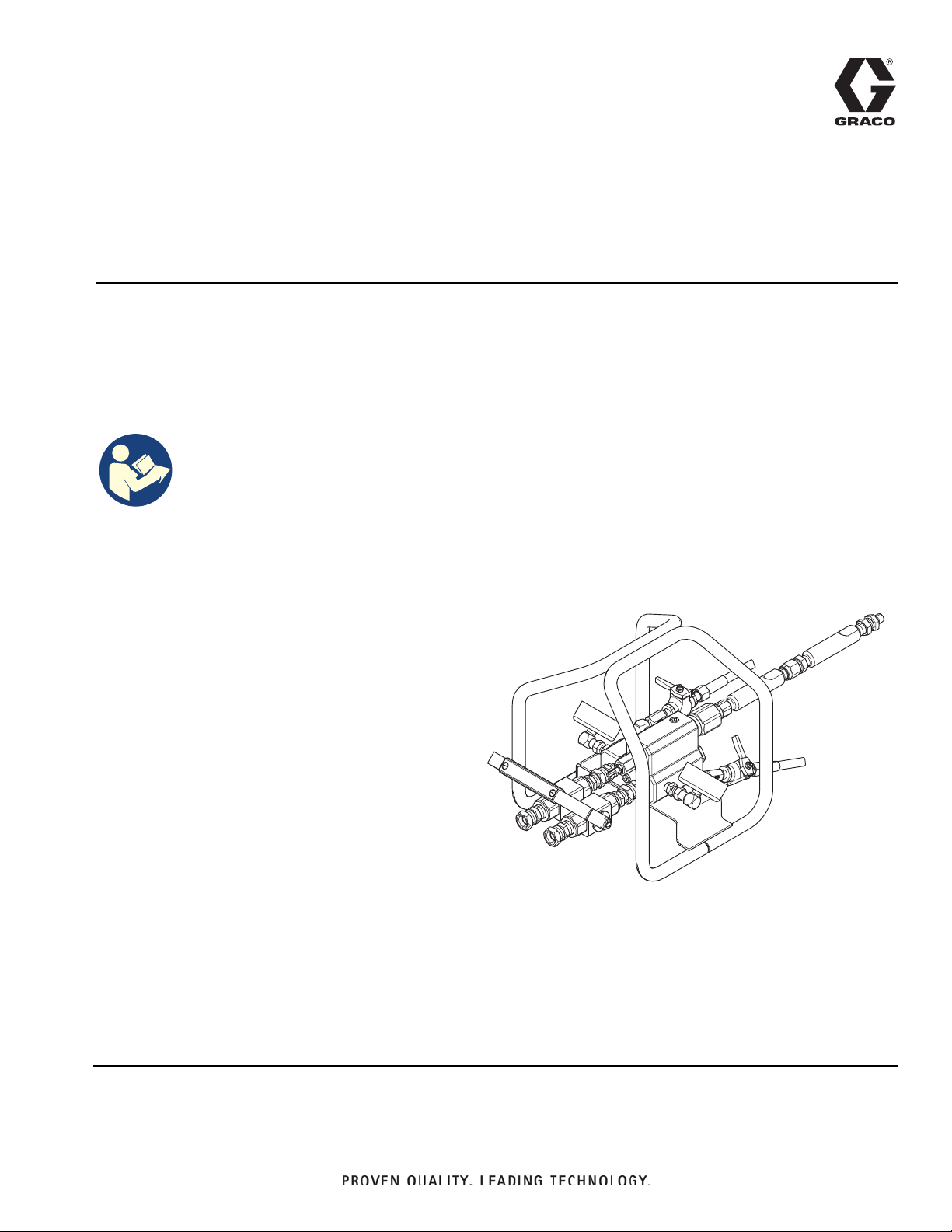
Standard XP Mix Manifold 262807 . . . . . . . . . . . . . . 9
Remote Manifold Carriage 262522 and 24Z934. . . 10
Remote Recirculation Kit 420033 . . . . . . . . . . . . . . 11
Quickset Manifold 24M398 . . . . . . . . . . . . . . . . . . . 12
Typical Installation. . . . . . . . . . . . . . . . . . . . . . . . . . 13
Overview. . . . . . . . . . . . . . . . . . . . . . . . . . . . . . . . . . . . 14
Remote Mix Manifold . . . . . . . . . . . . . . . . . . . . . . . 15
262522 Remote Mix Manifold Carriage . . . . . . . . . 15
24Z934 Remote Mix Manifold Heater Block Kit . . . 15
24M398 Quickset Manifold . . . . . . . . . . . . . . . . . . . 15
Installation . . . . . . . . . . . . . . . . . . . . . . . . . . . . . . . . . . 16
A and B Material Inlets . . . . . . . . . . . . . . . . . . . . . . 16
Solvent Inlet . . . . . . . . . . . . . . . . . . . . . . . . . . . . . . 16
Mixed Material Outlet . . . . . . . . . . . . . . . . . . . . . . . 16
Converting to Remote Mix Manifold . . . . . . . . . . . . 17
Installing Remote Recirculation Manifold . . . . . . . . 17
Grounding . . . . . . . . . . . . . . . . . . . . . . . . . . . . . . . . . . 18
Flush Before Using Equipment . . . . . . . . . . . . . . . . . 18
Ratio Check . . . . . . . . . . . . . . . . . . . . . . . . . . . . . . . . . 18
Operation . . . . . . . . . . . . . . . . . . . . . . . . . . . . . . . . . . . 19
Prime Remote Mix Manifold . . . . . . . . . . . . . . . . . . 19
Prime Solvent Hose,
Mixed Material Hose and Gun . . . . . . . . . . . . . 19
Pressure Relief Procedure . . . . . . . . . . . . . . . . . . . 21
Trigger Lock . . . . . . . . . . . . . . . . . . . . . . . . . . . . . . 21
Dispensing and Spraying . . . . . . . . . . . . . . . . . . . . . . 22
Flushing . . . . . . . . . . . . . . . . . . . . . . . . . . . . . . . . . 23
Volume Balancing the Mix Manifold . . . . . . . . . . . . . 24
Adjust Restriction at the Mix Manifold . . . . . . . . . . 24
Hose Selection for Feeding
A Remote Mix Manifold . . . . . . . . . . . . . . . . . . 24
Maintenance . . . . . . . . . . . . . . . . . . . . . . . . . . . . . . . . 26
Clean Static Mixers . . . . . . . . . . . . . . . . . . . . . . . . 26
Clean “B” Side Screen . . . . . . . . . . . . . . . . . . . . . . 26
Clean Mix Manifold Outlet . . . . . . . . . . . . . . . . . . . 26
Troubleshooting . . . . . . . . . . . . . . . . . . . . . . . . . . . . . 27
Repair . . . . . . . . . . . . . . . . . . . . . . . . . . . . . . . . . . . . . . 29
Cartridge Assemblies . . . . . . . . . . . . . . . . . . . . . . . 29
Remove Restrictor . . . . . . . . . . . . . . . . . . . . . . . . . 30
Assemble Restrictor . . . . . . . . . . . . . . . . . . . . . . . . 30
Parts . . . . . . . . . . . . . . . . . . . . . . . . . . . . . . . . . . . . . . . 32
Accessories . . . . . . . . . . . . . . . . . . . . . . . . . . . . . . . . . 36
Accessory Ports . . . . . . . . . . . . . . . . . . . . . . . . . . . 36
Technical Data. . . . . . . . . . . . . . . . . . . . . . . . . . . . . . . 37
End of Product Life . . . . . . . . . . . . . . . . . . . . . . . . . . . 37
Graco Standard Warranty. . . . . . . . . . . . . . . . . . . . . . 38

Related Manuals
3A0590R 3
Related Manuals
Manuals are available at www.graco.com
Component Manuals in English:
Model Information
Accessories
Manual Description
3A0420 XP Proportioner, Instructions-Parts
3A0421 Ratio Check Kit, Instructions-Parts
306861 Ball Valves, Check Valves, and Swivels, Instructions-Parts
339361 High Pressure Hose and Accessories Brochure
3A4381 XP-hf Proportioner, Instructions-Parts
3A6283 XPs-hf Proportioner, Instructions-Parts
3A5313 Xtreme-Wrap Water Heated Hose
3A7524 Xtreme-Wrap Electric Heated Hose
Model Mix Manifold
Maximum
Working Pressure
(A and B Materials)
Maximum Solvent
Pressure
Maximum Fluid
Temperature Approvals
262807
Standard
XP Mix
Manifold
7250 psi
(50 MPa, 500 bar)
5000 psi
(34.5 MPa, 345 bar)
160 °F
(71 °C)
24M398 Quickset Mix
Manifold
7250 psi
(50 MPa, 500 bar)
5000 psi
(34.5 MPa, 345 bar)
160 °F
(71 °C)
II 2G Ex h IIC T5 Gb
Model Description Maximum Working
Pressure
Maximum Fluid
Temperature
For use with
(items sold separately)
262522 Remote Mix Manifold
Carriage
262807
with Heated Hose
24Z934 Remote Manifold Carriage
(with heater block)
262807 and Water Heated
Hose System
420033 Remote Recirculation Kit 7250 psi
(50 MPa, 500 bar)
160 °F
(71 °C)
262807 or 24M398 with
Heated Hose

Warnings
43A0590R
Warnings
The following warnings are for the setup, use, grounding, maintenance, and repair of this equipment. The
exclamation point symbol alerts you to a general warning and the hazard symbols refer to procedure-specific risks.
When these symbols appear in the body of this manual or on warning labels, refer back to these Warnings.
Product-specific hazard symbols and warnings not covered in this section may appear throughout the body of this
manual where applicable.
WARNING
FIRE AND EXPLOSION HAZARD
Flammable fumes, such as solvent and paint fumes, in work area can ignite or explode. Paint or solvent
flowing through the equipment can cause static sparking. To help prevent fire and explosion:
• Use equipment only in well-ventilated area.
• Eliminate all ignition sources, such as pilot lights, cigarettes, portable electric lamps, and plastic drop
cloths (potential static sparking).
• Ground all equipment in the work area. See Grounding instructions.
• Never spray or flush solvent at high pressure.
• Keep work area free of debris, including solvent, rags and gasoline.
• Do not plug or unplug power cords, or turn power or light switches on or off when flammable fumes
are present.
• Use only grounded hoses.
• Hold gun firmly to side of grounded pail when triggering into pail. Do not use pail liners unless they
are anti-static or conductive.
•Stop operation immediately if static sparking occurs or you feel a shock.Do not use equipment until
you identify and correct the problem.
• Keep a working fire extinguisher in the work area.
EQUIPMENT MISUSE HAZARD
Misuse can cause death or serious injury.
• Do not operate the unit when fatigued or under the influence of drugs or alcohol.
• Do not exceed the maximum working pressure or temperature rating of the lowest rated system
component. See Technical Specifications in all equipment manuals.
• Use fluids and solvents that are compatible with equipment wetted parts. See Technical
Specifications in all equipment manuals. Read fluid and solvent manufacturer’s warnings. For
complete information about your material, request Safety Data Sheets (SDSs) from distributor or
retailer.
• Do not leave the work area while equipment is energized or under pressure.
• Turn off all equipment and follow the Pressure Relief Procedure when equipment is not in use.
• Check equipment daily. Repair or replace worn or damaged parts immediately with genuine
manufacturer’s replacement parts only.
• Do not alter or modify equipment. Alterations or modifications may void agency approvals and create
safety hazards.
• Make sure all equipment is rated and approved for the environment in which you are using it.
• Use equipment only for its intended purpose. Call your distributor for information.
• Route hoses and cables away from traffic areas, sharp edges, moving parts, and hot surfaces.
• Do not kink or over bend hoses or use hoses to pull equipment.
• Keep children and animals away from work area.
• Comply with all applicable safety regulations.

Warnings
3A0590R 5
SKIN INJECTION HAZARD
High-pressure fluid from gun, hose leaks, or ruptured components will pierce skin. This may look like
just a cut, but it is a serious injury that can result in amputation. Get immediate surgical treatment.
• Do not spray without tip guard and trigger guard installed.
• Engage trigger lock when not spraying.
• Do not point gun at anyone or at any part of the body.
• Do not put your hand over the spray tip.
• Do not stop or deflect leaks with your hand, body, glove, or rag.
• Follow the Pressure Relief Procedure when you stop spraying and before cleaning, checking, or
servicing equipment.
• Tighten all fluid connections before operating the equipment.
• Check hoses and couplings daily. Replace worn or damaged parts immediately.
THERMAL EXPANSION HAZARD
Fluids subjected to heat in confined spaces, including hoses, can create a rapid rise in pressure due to
the thermal expansion. Over-pressurization can result in equipment rupture and serious injury.
• Open a valve to relieve the fluid expansion during heating.
• Replace hoses proactively at regular intervals based on your operating conditions.
TOXIC FLUID OR FUMES HAZARD
Toxic fluids or fumes can cause serious injury or death if splashed in the eyes or on skin, inhaled or
swallowed.
• Read Safety Data Sheets (SDSs) for handling instructions and to know the specific hazards of the
fluids you are using, including the effects of long-term exposure.
• When spraying, servicing equipment, or when in the work area, always keep work area
well-ventilated and always wear appropriate personal protective equipment. See Personal
Protective Equipment warnings in this manual.
• Store hazardous fluid in approved containers, and dispose of it according to applicable guidelines.
BURN HAZARD
Equipment surfaces and fluid that is heated can become very hot during operation. To avoid severe
burns:
• Do not touch hot fluid or equipment.
WARNING

Warnings
63A0590R
PRESSURIZED ALUMINUM PARTS HAZARD
Use of fluids that are incompatible with aluminum in pressurized equipment can cause serious chemical
reaction and equipment rupture. Failure to follow this warning can result in death, serious injury, or
property damage.
• Do not use 1,1,1-trichloroethane, methylene chloride, other halogenated hydrocarbon solvents or
fluids containing such solvents.
• Do not use chlorine bleach.
• Many other fluids may contain chemicals that can react with aluminum. Contact your material supplier
for compatibility.
PERSONAL PROTECTIVE EQUIPMENT
Always wear appropriate personal protective equipment and cover all skin when spraying, servicing
equipment, or when in the work area. Protective equipment helps prevent serious injury, including
long-term exposure; inhalation of toxic fumes, mists or vapors; allergic reaction; burns; eye injury and
hearing loss. This protective equipment includes but is not limited to:
• A properly fitting respirator, which may include a supplied-air respirator, chemically impermeable
gloves, protective clothing and foot coverings as recommended by the fluid manufacturer and local
regulatory authority.
• Protective eyewear and hearing protection.
WARNING

Important Isocyanate (ISO) Information
3A0590R 7
Important Isocyanate (ISO) Information
Isocyanates (ISO) are catalysts used in two-component materials.
Isocyanate Conditions Keep Components A and B
Separate
Spraying or dispensing fluids that contain isocyanates
creates potentially harmful mists, vapors, and
atomized particulates.
• Read and understand the fluid manufacturer’s
warnings and Safety Data Sheets (SDSs) to know
specific hazards and precautions related to
isocyanates.
• Use of isocyanates involves potentially hazardous
procedures. Do not spray with this equipment
unless you are trained, qualified, and have read
and understood the information in this manual and
in the fluid manufacturer’s application instructions
and SDSs.
• Use of incorrectly maintained or mis-adjusted
equipment may result in improperly cured
material. Equipment must be carefully maintained
and adjusted according to instructions in the
manual.
• To prevent inhalation of isocyanate mists, vapors,
and atomized particulates, everyone in the work
area must wear appropriate respiratory protection.
Always wear a properly fitting respirator, which
may include a supplied-air respirator. Ventilate the
work area according to instructions in the fluid
manufacturer’s SDSs.
• Avoid all skin contact with isocyanates. Everyone
in the work area must wear chemically
impermeable gloves, protective clothing and foot
coverings as recommended by the fluid
manufacturer and local regulatory authority.
Follow all fluid manufacturer recommendations,
including those regarding handling of
contaminated clothing. After spraying, wash hands
and face before eating or drinking.
Cross-contamination can result in cured material in
fluid lines which could cause serious injury or damage
equipment. To prevent cross-contamination:
• Never interchange component A and component
B wetted parts.
• Never use solvent on one side if it has been
contaminated from the other side.

Important Isocyanate (ISO) Information
83A0590R
Moisture Sensitivity of
Isocyanates
Exposure to moisture (such as humidity) will cause ISO
to partially cure, forming small, hard, abrasive crystal
that become suspended in the fluid. Eventually a film will
form on the surface and the ISO will begin to gel,
increasing in viscosity.
Partially cured ISO will reduce performance and the life
of all wetted parts.
• Always use a sealed container with a desiccant
dryer in the vent, or a nitrogen atmosphere. Never
store ISO in an open container.
• Keep the ISO pump wet cup or reservoir (if
installed) filled with appropriate lubricant. The
lubricant creates a barrier between the ISO and the
atmosphere.
• Use only moisture-proof hoses compatible with
ISO.
• Never use reclaimed solvents, which may contain
moisture. Always keep solvent containers closed
when not in use.
• Always lubricate threaded parts with an appropriate
lubricant when reassembling.
NOTE: The amount of film formation and rate of
crystallization varies depending on the blend of ISO, the
humidity, and the temperature.
Changing Materials
Changing the material types used in your equipment
requires special attention to avoid equipment damage
and downtime.
• When changing materials, flush the equipment
multiple times to ensure it is thoroughly clean.
• Always clean the fluid inlet strainers after flushing.
• Check with your material manufacturer for
chemical compatibility.
• When changing between epoxies and urethanes or
polyureas, disassemble and clean all fluid
components and change hoses. Epoxies often
have amines on the B (hardener) side. Polyureas
often have amines on the B (resin) side.
NOTICE
NOTICE

Component Identification
3A0590R 9
Component Identification
Standard XP Mix Manifold 262807
Ref. Description
AA “A” Material Inlet
AB “B” Material Inlet
AC Solvent Inlet, 1/4 npt(m)
AE Dual Shutoff Handle
AF Hardener Restrictor Adjustment
AG Solvent Shutoff Handle
AH Mix Manifold Outlet, 1/2 npt(f) with 3/8 npt(m) adapter
AP Accessory Ports (see Accessory Ports, page 36)
AR Solvent Inlet Check Valve
AV Fasteners (assembled on Mix Manifold)
$&
$5
$)
$(
$%
$$
$3
$+
$9
WLD
$*
FIG. 1: Mix Manifold Component Identification

Component Identification
10 3A0590R
Remote Manifold Carriage 262522 and 24Z934
Ref. Description
BC Remote Manifold Carriage
BD Long Fasteners (shipped loose)
BE Heater Block
WLD
%(
%&
%'
%'
%&
Remote Manifold Carriage
with Heater Block 24Z934
Remote Manifold Carriage
FIG. 2: Remote Manifold Heater Block Component Identification

Component Identification
3A0590R 11
Remote Recirculation Kit 420033
Ref. Description
CA Recirculation Manifold “A” Inlet
CB Recirculation Manifold “B” Inlet
CD Recirculation Hose Shut-Off Valve
CE Remote Recirculation Handle
CF Remote Recirculation Tube
CG Remote Recirculation Hose
CH Bushing (shipped loose)
CJ Adapter Fitting (shipped loose)
CK “A” Fitting End
CL “B” Fitting End
CR Remote “B” Recirculation Port
CS Remote “A” Recirculation Port
WLD
&)
&'
&*
&+
&-
&6
&.
&%
&$
&5
&(
&/
FIG. 3: Remote Recirculation Kit Component Identification

Component Identification
12 3A0590R
Quickset Manifold 24M398
Ref. Description
AA “A” Material Inlet
AB “B” Material Inlet
AE Dual Shutoff Handle
AF Hardener Restrictor Adjustment
AV Fasteners
BC Remote Manifold Carriage
DB “B” Side Solvent Line
DC “B” Side Solvent Shutoff
DD “A” Side Solvent Line
DE “A” Side Solvent Shutoff
DF Solvent Inlet Tree
DG Primary Mix Housing
DH Static Mixing Element (not shown, inside DH)
DJ Fluid Whip Hose (shipped loose)
DK Adapter Fitting (shipped loose)
DL XHF Gun (shipped loose)
WLD
')
'&
'%
'*'+
''
'(
%&
$9
'-
'/
'.
$$
$%
$)
$(
FIG. 4: Quickset Manifold Component Identification

Component Identification
3A0590R 13
Typical Installation
Ref. Description
CSolventPump
D Recirculation Lines
E Recirculation Handles
F Recirculation Manifold
G Solvent Supply Hose
H Solvent Hose Extension
J Primary Mixer Housing
K Fluid Whip Hose
L Airless Spray Gun
M Static Mixing Element (not shown inside J or P)
N Fluid Mix Hose
WLD
6
5
+
%&
5
$'
)
('
'
$*
$(
*
6
&
&)
&)
&(
&*
&(
&5
&%
-0
-0
1
30
.
/
&6
AB
AB
&+
&-
Ref. Description
P Clean-up Mixer Tube
R “B” Recirculation Hose
S “A” Recirculation Hose
AD Mix Manifold
AE Dual Shutoff Handle
AG Solvent Shutoff Handle
BC Remote Carriage
CE Remote Recirculation Handle
CF Remote Recirculation Tube
CR Remote “B” Recirculation Port
CS Remote “A” Recirculation Port
FIG. 5: Typical Installation

Overview
14 3A0590R
Overview
The left side of the mix manifold is intended for the major
volume material, or the higher viscosity material if using a
1:1 volume mix. This side is referred to throughout the
manual as the resin side or “A” side.
The right side is referred to as the Hardener side or “B”
side. The “B” side incorporates an adjustable restrictor for
balancing the system back pressure and flow.
See FIG. 2 to view flow of “A” and “B” material inside the
Mix Manifold.
The resin and hardener enter the mix manifold through the
manifold inlet ports and spring loaded carbide ball checks.
The “A” material flows through the manifold to the material
outlet port. The injector tube creates a hollow stream of “A”
material for the “B” material to fill once the hardener exits
the injector tube. The resin and hardener material mix after
they have left the mix manifold.
On the standard XP mix manifold, mixed material is flushed
out by sending a flush solvent through the B side center
tube. On the Quickset mix manifold, solvent is also flushed
across the A side fluid check valve.
FIG. 6: Cross-Section Side Views of A and B Flow
“B” Side of Mix Manifold“A” Side of Mix Manifold
Mixed Material A Side Material B Side Material
AF
AH
AH
Solvent Fluid Inlet
r_258987_3a0420_2a
r_258987_3a0420_3a
Carbide
Check Valve
AF
“B” Inlet Ball Valve
“A” Inlet Ball Valve
(on each side)
“B” side solvent
flush inlet after
restrictor (Used
on both models)
“A” side solvent
flush inlet
across check
ball added on
Quickset model. (on “B” side)
“B” side flow
after check
valve

Overview
3A0590R 15
Remote Mix Manifold
The standard XP mix manifold can be removed from the
proportioner and mounted closer to the gun. This
reduces the volume of mixed material and flush solvent
for quick setting materials (less than 10 minute pot life).
When the standard XP mix manifold is mounted remote
from the proportioner, follow the steps in Volume
Balancing the Mix Manifold on page 24.
262522 Remote Mix Manifold
Carriage
The carriage holds and protects the mix manifold
assembly when mounted remotely.
24Z934 Remote Mix Manifold
Heater Block Kit
The remote mix manifold carriage 262522 with heating
block is used with water jacketed heated hoses, heating
fluid is circulated under the mix manifold to maintain
temperature. See your water jacketed heated hoses
manual for details for connecting heated hoses.
24M398 Quickset Manifold
The remote mix manifold with dual flush and pressure
gauges is used for quick setting materials. The mix
manifold comes assembled on the carriage with static
mixers, and includes mixed material hose and XTR gun.
Before installing, follow steps in Volume Balancing the
Mix Manifold on page 24.

Installation
16 3A0590R
Installation
For assistance in setting up a plural component sprayer,
contact your Graco distributor, to ensure that you select
the proper type and size equipment for your system.
A and B Material Inlets
Standard XP Mix Manifold 262807 (See illustration in
FIG. 1 on page 9) and Quickset Mix Manifold 24M398:
The A and B material inlets (AA and AB) are equipped
with 1/2 npt(f) ball valves. Connect 1/2 in., 3/8 in., or 1/4
in. npsm(f) fluid hoses with adapter nipples as needed.
Solvent Inlet
For Standard XP Mix Manifold 262807: Connect the
solvent extension hose (H) to the solvent supply hose
(G). Connect the other end of the solvent extension
hose (H) to the solvent inlet (AC).
For Quickset Mix Manifold 24M398: Connect the
solvent supply hose (G) to the solvent inlet tee (DF).
Use a Graco approved grounded hose rated to
withstand the maximum fluid working pressure of the
solvent pump. The hose core must be chemically
compatible with the solvent being used, such as nylon or
PTFE.
Mixed Material Outlet
-0
30
-0
WLD
Standard XP Mix Manifold 262807
Connect the outlet to two primary static mixer tubes (J),
with mixer elements (M), to the mix hose (N), cleanup
mixer (P), whip hose (K), and spray gun (L).
Quickset Manifold 24M398
Connect the whip hose (DJ), adapter fitting (DK) and
spray gun (DL).
NOTICE
To prevent creating a flare on the mixer tube, do not
use a union swivel end on the mix tube inlet.
NOTICE
To prevent material from curing inside the manifold,
never split the flow to multiple guns until the two
fluids are mixed after the mix manifold assembly.

Installation
3A0590R 17
Converting to Remote Mix
Manifold
Loosen the swivel fittings of the A and B material inlets
(AA, AB) and remove the standard XP mix manifold
(AD).
For 262522: Use the mounting fasteners (AV) to mount
the standard XP mix manifold (AD) to the remote
carriage. See Mounting without Carriage (page 17)if
not using a remote carriage.
For 24Z934: Remove the existing mounting fasteners
(AV) and discard. Use the long fasteners (BD) (shipped
loose with kit) to install the standard XP mix manifold to
the remote carriage with heater manifold. Refer to your
heated hose manual for heated hose connection
instructions.
Installing Remote Recirculation
Manifold
1. Follow the Converting to Remote Mix Manifold
procedure on page 17.
2. Connect the remote recirculation manifold to the mix
manifold by connecting the “A” fitting end (CK) to A
material inlets (AA) and the “B” fitting end (CL) to B
material inlets (AB).
3. Connect “A” and “B” material hoses to the
recirculation manifold inlet (CA, CB).
4. Connect the recirculation hoses (R, S) of the heated
hose bundle to the corresponding remote
recirculation ports (CR, CS).
NOTE: Not all heated hose bundles include
recirculation hoses.
5. Connect the recirculation hoses (R, S) to the
corresponding return hoses.
Mounting without Carriage
To mount the bare manifold, drill two holes in the
mounting surface, and secure with the two 1/4-20
screws (28).
1.1 in. (27.94 mm)
9/32 diameter

Grounding
18 3A0590R
Grounding
The equipment must be grounded to reduce the risk
of static sparking. Static sparking can cause fumes to
ignite or explode. Grounding provides an escape wire
for the electric current. See your sprayer manual for
additional warning information.
•Pump: use ground wire and clamp as instructed in
your sprayer manual.
•Air and fluid hoses: use only electrically
conductive hoses. with a maximum of 500 ft. (150
m) combined hose length to ensure grounding
continuity. Check electrical resistance of hoses. If
total resistance to ground exceeds 29 megohms,
replace hose immediately.
•Mix Manifold and Solvent Flush System: Use
only a Graco approved grounded solvent hose. Not
all heated hoses are grounded. The mix manifold
primary ground is through the solvent hose. Make
sure that the solvent pump is properly grounded as
instructed in your solvent pump manual. Make sure
there is electrical continuity from the spray tip to the
grounded solvent pump.
•Air compressor: follow manufacturer’s
recommendations.
•Spray gun: ground through connection to a
properly grounded fluid hose and pump.
•Fluid supply container: follow local code.
•Object being sprayed: follow local code.
•Solvent pails used when flushing: follow local
code. Use only conductive metal pails, placed on a
grounded surface. Do not place the pail on a
non-conductive surface, such as paper or
cardboard, which interrupts grounding continuity.
•To maintain grounding continuity when flushing
or relieving pressure: hold metal part of the spray
gun firmly to the side of a grounded metal pail, then
trigger the gun.
Flush Before Using
Equipment
The equipment was tested with lightweight oil, which is
left in the fluid passages to protect parts. To avoid
contaminating your fluid with oil, flush the equipment
with a compatible solvent before using the equipment.
See Flushing, page 16.
Ratio Check
Perform the ratio check procedure after any changes to
the proportioning system. Use Ratio Check Kit 24F375
to check the ratio at the mix manifold. See manual
3A0421 for instructions and parts.
NOTE: To prevent an inaccurate ratio check when feed
pumps are used in your system, the feed pressure
cannot be more than a maximum of 25% of the
proportioner outlet pressure while dispensing. High feed
pressure can float the proportioner pump check balls,
resulting in an inaccurate ratio check.

Operation
3A0590R 19
Operation
Prime Remote Mix Manifold
To help prevent injury from solvents and heated
fluids, wear gloves when using solvents and/or if the
fluid temperature exceeds 110 °F (43 °C).
1. Follow steps in your XP proportioner manual to
prime the proportioner.
WLD
&(
$(
2. Close the dual shutoff handle (AE).
3. Open the remote recirculation handle (CE), and
make sure the remote recirculation tubes (CG) are
inserted in the correct hopper.
NOTE: If a remote recirculation manifold is not
installed, disconnect the material hoses at the
material inlets (AA and AB). Prime the material
hoses over grounded metal pails, then reconnect
the material hoses.
4. Run the XP pumps until fluid flows through the “A”
and “B” material hoses.
Prime Solvent Hose, Mixed
Material Hose and Gun
1. Connect a ground wire (not included) to a metal pail
of solvent.
WLD
$*
WLD
'&
'(
2. Dispense solvent to the remote mix manifold. See
your XP manual for operation instructions.
3. Open the solvent shutoff valve (AG) on the mix
manifold.
4. On Quickset manifolds, open the “A” side solvent
valve (DE) and “B” side solvent valve (DC).

TI1948A
Operation
20 3A0590R
5. Make sure the trigger lock is engaged. Remove the
spray tip.
6. Disengage the trigger lock and trigger the gun into a
grounded pail. Use a pail lid with a hole to dispense
through.
NOTE: To prevent splash-back, use a rag to seal
around the hole and gun. Be careful to keep fingers
away from the front of the gun.
7. Close the solvent flush valves and trigger the gun to
relieve pressure. Engage the trigger lock.
This manual suits for next models
1
Table of contents
Other Graco Service Equipment manuals
Popular Service Equipment manuals by other brands

Sealey
Sealey MS070CR instructions

Sicam
Sicam FALCO EVO 622 Original instructions

Blue Giant
Blue Giant ML10 Series Installation & owner's manual

Baileigh Industrial
Baileigh Industrial UMB-900 Operator's manual

Carlisle Fluid Technologies
Carlisle Fluid Technologies TRiSK DeVILBISS TRU-CURE IR3S Service manual

Kirkland Signature
Kirkland Signature TBTL0206A-X manual