manuals.online logo
Brands
  1. Home
  2. •
  3. Brands
  4. •
  5. Sealey
  6. •
  7. Service Equipment
  8. •
  9. Sealey PT1150.V2 User manual

Sealey PT1150.V2 User manual

This manual suits for next models

1

Other Sealey Service Equipment manuals

Sealey AK467D User manual

Sealey

Sealey AK467D User manual

Sealey DG01 User manual

Sealey

Sealey DG01 User manual

Sealey TST10 User manual

Sealey

Sealey TST10 User manual

Sealey AK36D.V2 User manual

Sealey

Sealey AK36D.V2 User manual

Sealey MK51.V4 User manual

Sealey

Sealey MK51.V4 User manual

Sealey TH003.V2 User manual

Sealey

Sealey TH003.V2 User manual

Sealey AS2500 User manual

Sealey

Sealey AS2500 User manual

Sealey RE23RS User manual

Sealey

Sealey RE23RS User manual

Sealey AK467D User manual

Sealey

Sealey AK467D User manual

Sealey ADT3 User manual

Sealey

Sealey ADT3 User manual

Sealey SA37/94 User manual

Sealey

Sealey SA37/94 User manual

Sealey RE012 User manual

Sealey

Sealey RE012 User manual

Sealey TD2525CS User manual

Sealey

Sealey TD2525CS User manual

Sealey VS0208 User manual

Sealey

Sealey VS0208 User manual

Sealey ms1824.v2 User manual

Sealey

Sealey ms1824.v2 User manual

Sealey SAR01 User manual

Sealey

Sealey SAR01 User manual

Sealey AK449D User manual

Sealey

Sealey AK449D User manual

Sealey W508T.V3 User manual

Sealey

Sealey W508T.V3 User manual

Sealey VS0041 User manual

Sealey

Sealey VS0041 User manual

Sealey VS301 User manual

Sealey

Sealey VS301 User manual

Sealey WS650.V3 User manual

Sealey

Sealey WS650.V3 User manual

Sealey AK456DX User manual

Sealey

Sealey AK456DX User manual

Sealey TP69.V3 User manual

Sealey

Sealey TP69.V3 User manual

Sealey AS10000 User manual

Sealey

Sealey AS10000 User manual

Popular Service Equipment manuals by other brands

Magneti Marelli ATF EXTRA PRO user manual

Magneti Marelli

Magneti Marelli ATF EXTRA PRO user manual

Hyundai Midtronics GRX-5100 instruction manual

Hyundai

Hyundai Midtronics GRX-5100 instruction manual

Tronair 01-1229-0011 Operation & service manual

Tronair

Tronair 01-1229-0011 Operation & service manual

ULTIMATE SPEED HG02236 Assembly and Safety Advice

ULTIMATE SPEED

ULTIMATE SPEED HG02236 Assembly and Safety Advice

CEMB DWA1000CWAS manual

CEMB

CEMB DWA1000CWAS manual

Invacare TDX SP Assembly, installation and operating instructions

Invacare

Invacare TDX SP Assembly, installation and operating instructions

MAHLE AIR-NEX 9310 quick start guide

MAHLE

MAHLE AIR-NEX 9310 quick start guide

Waeco ASC 6300 G operating manual

Waeco

Waeco ASC 6300 G operating manual

Reflex Fillcontrol Auto Series operating manual

Reflex

Reflex Fillcontrol Auto Series operating manual

Gree CE42-24/F owner's manual

Gree

Gree CE42-24/F owner's manual

MSW Motor Technics MSW-DA-21 user manual

MSW Motor Technics

MSW Motor Technics MSW-DA-21 user manual

Multipick MHP II instructions

Multipick

Multipick MHP II instructions

Zell AC1800 Operation manual

Zell

Zell AC1800 Operation manual

RFL C37.94 instruction data

RFL

RFL C37.94 instruction data

Kärcher IP 55 operating instructions

Kärcher

Kärcher IP 55 operating instructions

CMO SPRK.ALU instruction manual

CMO

CMO SPRK.ALU instruction manual

Lube1 PROGEAR XC Premium Use and maintenance manual

Lube1

Lube1 PROGEAR XC Premium Use and maintenance manual

Comco 523 Series Installation and operator's manual

Comco

Comco 523 Series Installation and operator's manual

manuals.online logo
manuals.online logoBrands
  • About & Mission
  • Contact us
  • Privacy Policy
  • Terms and Conditions

Copyright 2025 Manuals.Online. All Rights Reserved.

INSTRUCTIONS FOR:
PALLET TRUCKS
MODEL No: PT1150.V2 & PT1220.V2
Thank you for purchasing a Sealey product. Manufactured to a high standard this product will, if used according to these instructions
and properly maintained, give you years of trouble free performance.
1. SAFETY INSTRUCTIONS
IMPORTANT: PLEASE READ THESE INSTRUCTIONS CAREFULLY. NOTE THE SAFE OPERATIONAL REQUIREMENTS, WARNINGS & CAUTIONS.
USE THE PRODUCT CORRECTLY AND WITH CARE FOR THE PURPOSE FOR WHICH IT IS INTENDED. FAILURE TO DO SO MAY CAUSE
DAMAGE AND/OR PERSONAL INJURY AND WILL INVALIDATE THE WARRANTY. PLEASE KEEP INSTRUCTIONS SAFE FOR FUTURE USE.
2. INTRODUCTION & SPECIFICATION
DO NOT use a faulty or damaged truck.
Before using the truck all parts and working mechanisms should
be checked for wear or damage. Pay particular attention to the
wheels, handle and fork lifting and lowering mechanism. Any
parts found to be worn, damaged or suspect should be repaired
or replaced before the truck is used.
All repairs must be carried out by an authorised Sealey service
agent.
Personnel who operate the truck and those in the vicinity of
operation should wear safety shoes with reinforced toe caps at all
times.
Never place any part of your body in the lifting mechanism or
under the forks or load.
DO NOT allow others to ride on the truck.
DO NOT lift or move unstable or loosely stacked loads.
Take special care when moving long, high or wide loads in order
not to dislodge the load by striking any architectural features,
permanent fixtures, vehicles or people in the area of operation.
Always ensure that the load is evenly distributed across the forks
with the centre of the load being at the halfway point of the length
of the forks.
Do not overload the truck - refer to the specification for maximum
permitted load.
If a load is left unattended even for a very short period of time it
should be lowered to the ground.
When not in use the truck should be left in the lowered position.
Ensure that the width and length of the forks is correct for the
pallet to be lifted.
Ensure that the truck is sufficiently inserted into the pallet to lift
the full depth of the pallet.
Use the truck on level, flat, hard surfaces.
DO NOT use truck on sloping or uneven ground and do not
attempt to negotiate curbs, steps or ramps.
The operator of the truck must be physically capable of controlling
the load selected; particularly in relation to stopping a rolling load.
 When the truck is not in use, lower the forks and park the truck
where it will not be a hazard.
3. ASSEMBLY
Introduction. Heavy-duty trucks suitable for warehouse and general
handling duties. Polyurethane, non-marking wheels and tandem
loading rollers with sealed-for-life bearings all-round. Hydraulic unit
with chromed ram and piston for resistance to corrosion. Single
bogey wheels with drop nose for smooth pallet entry.
Specification.
Model No. ....................................... PT1150.V2 ...............PT1220.V2
Capacity................................................. 2500kg .....................2500kg
Minimum height ....................................... 85mm .......................85mm
Maximum height ................................... 200mm ......................200mm
Fork Length ......................................... 1150mm ...................1220mm
Width over Forks ................................... 540mm.................. 685 mm
Fork Spread........................................... 230mm ......................365mm
roll pin will lie in the groove made for it in the pump casting.
3.3 Using a hammer, insert the pivot pin (5) through both
components from right to left. Once the pivot pin is in
position, drive another roll pin through the hole in the other
end of the pivot pin.
3.4 Move the lever control at the top of the handle into it's highest
position and hold it there.
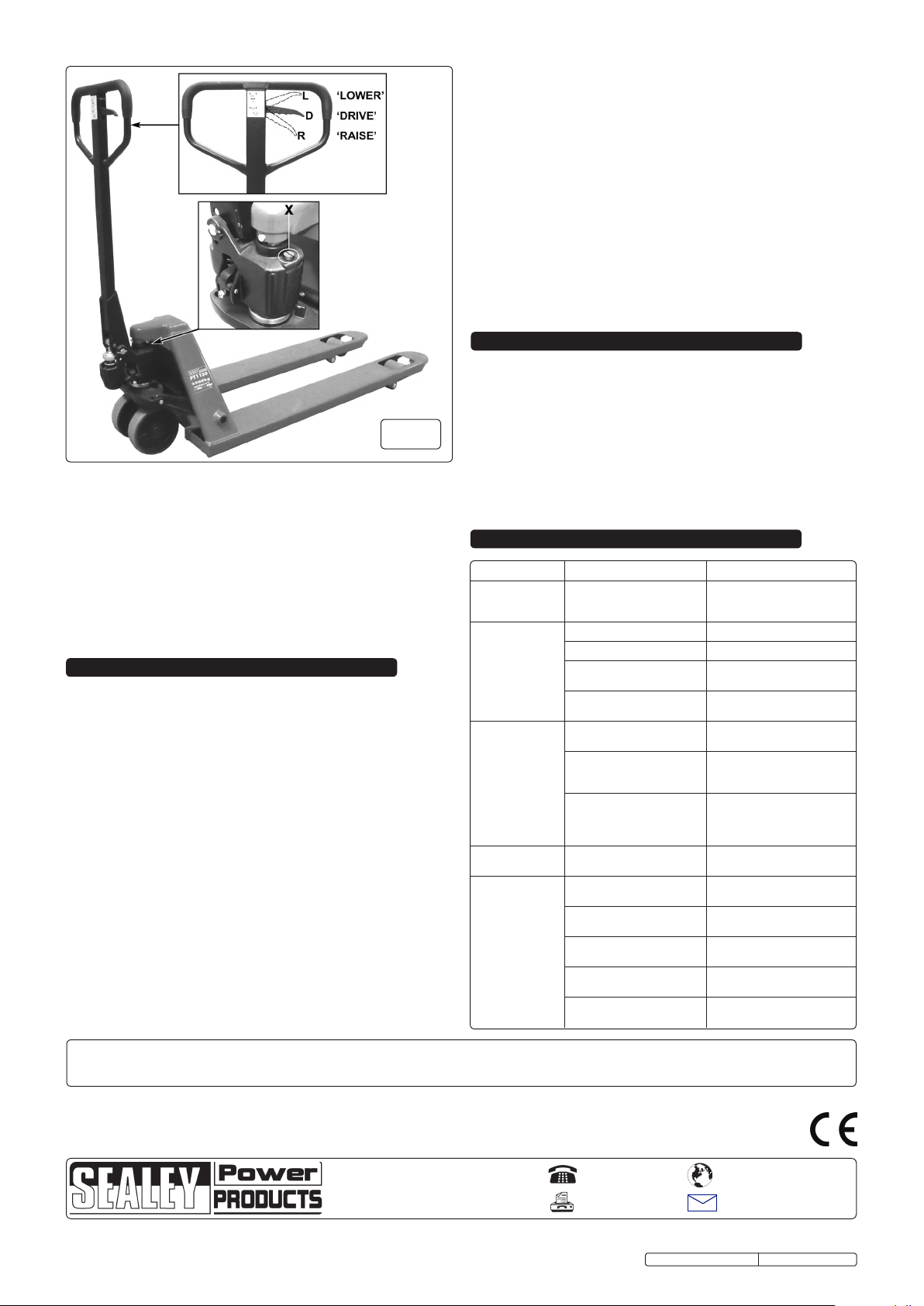
3.5 Referring to the inset cross section in fig.1, Insert the chain (2)
with adjusting bolt (6) and nut (8) attached through the hole in
the centre of the pivot pin.
3.6 There is a transit pin just below the main handle pivot which
needs to be removed. Lower the handle down so that the
rolling sleeve (3) bears down on top of the piston and remove
the transit pin.
3.7 Move the lever control at the top of the handle into it's lowest
position. Then raise the rocking lever plate (7) which sits within
the main casting and move the chain adjusting bolt (6) into the
slot in the end of the plate so that the adjusting nut (8) is now
underneath the plate as shown on the inset cross section in fig.1.
3.1 Identify the handle pivot pin (5) and tap a roll pin (9) through
one end of it so that it sticks out equally either side.
3.2 Position yourself behind the truck and insert the handle
assembly into the pump casting (see fig.1). Align the pivot
holes at the base of the handle with the pivot holes in the
casting. Take the pivot pin and orientate it so that the inserted
4. ADJUSTMENTS
4.1 The control lever (see fig.2) has three positions as follows:-
RAISE - Lever in lowest position.
DRIVE - Lever in centre position.
LOWER - Lever held in up position. When released the lever
returns to the drive position.
4.2 If the lever does not work in the prescribed way it can be
adjusted using the nut (8) at the bottom of the adjusting rod
(6) which is attached to the chain (2). See fig.1.
4.3 If the truck elevates whilst pumping in the Drive position, turn
the adjusting nut clockwise until the pumping action no longer
raises the truck and the Drive functions correctly.
Original Language Version
fig.1
PT1150.V2 & PT1220.V2 Issue No.1 - 00/00/00
5. OPERATING THE TRUCK
6. MAINTENANCE
7. TROUBLE SHOOTING
5.1 Before using the truck you must read and understand the
safety instructions in Section 1.The truck should only be
operated by those persons who have been trained in its use.
5.2 The operator must be physically capable of pushing or pulling
the load and must also be capable of stopping a rolling load.
5.3 Before lifting any load the operator should check that the pallet
is the correct width and length for the truck and that the pallet
itself is not damaged.
5.4 The operator should ensure that the load on the pallet is safe
to move. If the load appears to be loosely stacked, unevenly
distributed, too high or too wide it should be repacked safely
before moving. Also check that the weight of the load is within
the capacity of the truck
5.5 Lowering the truck. ( See fig.2 - L ) Before inserting the truck
into the pallet ensure that the truck forks are in their lowest
position by pulling the operating lever into the upper position
and holding it there until the truck has settled down to the
lowest level.
5.6 Drive position. ( See fig.2 - D ) The lever can now be
released and will return to the middle drive position.
5.7 Push the truck into the pallet ensuring that it is fully inserted. If
the pallet is shorter than the forks the load should be placed at
the centre point of the length of the forks.
5.8 Raising a load. ( See fig.2 -R ) To lift the load push the
operating lever to its lowest position where it will latch. Pump
the handle up and down to lift the load from the floor. When
the forks reach their maximum height the lifting action will stop
even if you continue to pump the handle.
5.9 Before you move off return the operating lever to its neutral
position.
5.10 Due care should be taken when manoeuvring a load to ensure
that no collision takes place with any objects or people.
5.11 The faster the truck is moved the more difficult it will be to stop
it. Therefore proceed at a slow and even pace.
5.12 Bring the truck to a stop where required and lower the load to
the floor by pulling the operating lever to its highest position
and holding it there until the load has settled to the floor.
5.13 It is not recommended that the load is lowered whilst the truck
is still moving as a sudden stop may dislodge the load causing
damage to property and/or people.
4.4 If the truck descends whilst pumping in the Drive position, turn
the adjusting nut counter clockwise until the truck does not
lower.
4.5 If the truck does not descend when the control lever is held in
the highest position turn the nut clockwise until lowering is
acheived. Now check the Drive position as described in
sections 4.2 and 4.3.
4.6 If the truck does not raise while pumping with the control lever
in the lowest position turn the adjusting nut counter clockwise
until raising is acheived, then check that the other two control
lever positions still function correctly.
6.1 The oil level should be checked every six months. The system
contains 0.4lt of hydraulic oil which should conform to
ISO VG32. The viscosity should be 32cSt at 40ºC . ( See oil
level / filler screw ‘X’ in fig.2 ) Sealey hydraulic oil is ideal.
6.2 To purge air from the system hold the operating lever in the
lowering position until the truck has descended to its lowest
level then pump the handle up and down 8 to 10 times.
6.3 Apply a long life grease to all bearings and shafts once a month.
Original Language Version
THE PROBLEM THE CAUSE THE SOLUTION
1. The forks do not
reach maximum
height.
Hydraulic oil level too low. Top up the oil.
2. The forks do not
raise.
No hydraulic oil Fill with hydraulic oil
The oil is contaminated. Change the oil.
The lifting/lowering mechanism
needs adjustment.
Follow procedure in Section 4.
Air in the hydraulic system. Purge the air as described in
Section 6.
3. The forks will not
descend.
The lifting/lowering mechanism
needs adjustment.
Adjust as described in Section 4.
Truck stored in raised position
allowing exposed piston rod to
corrode and jam.
Lubricate rod regularly and store
truck in lowered position.
Piston rod or pump body
deformed as a result of
overloading or unbalanced
load.
Replace piston rod or pump
body.
4. Leaks. Seals worn, damaged or
cracked.
Replace seals.
5. The forks
descend and
cannot be
maintained in the
raised position.
The lifting/lowering mechanism
needs adjustment.
Adjust as described in Section 4
.
Release valve not fully closed
due to impurities in oil.
Change the oil.
Air in the hydraulic system. Purge the air as described in
Section 6.
Seals worn, damaged or
cracked.
Replace seals.
Parts of hydraulic system
cracked or worn.
Inspect and replace.
fig.2
NOTE: It is our policy to continually improve products and as such we reserve the right to alter data, specifications and component parts without prior notice.
IMPORTANT: No liability is accepted for incorrect use of this product.
WARRANTY: Guarantee is 12 months from purchase date, proof of which will be required for any claim.
INFORMATION: For a copy of our latest catalogue and promotions call us on 01284 757525 and leave your full name and address, including postcode.
01284 757500
01284 703534
sales@sealey.co.uk
Sole UK Distributor, Sealey Group,
Kempson Way, Suffolk Business Park,
Bury St. Edmunds, Suffolk,
IP32 7AR
www.sealey.co.uk
Web
email
PT1150.V2 & PT1220.V2 Issue No.1 - 00/00/00
Parts support is available for theses products. To obtain a parts listing and/or diagram, please log on to
www.sealey.co.uk, email sales@sealey.co.uk or phone 01284 757500.