LTR BSG 03_230 User manual

Brake Service Unit
BSG 03_230 / BSG 03_230A
100501_1 / 100500_1MANUAL
BSG

- 2 -
①START button
②ON/OFF switch (device)
③ON/OFF switch (extraction)
④Fuse
⑤Pressure gauge
⑥Pressure regulator (0…4 bar)
⑦Catch container
⑧Suction hose
⑨Return hose
⑩Hose unit
⑪Tray for original brake fluid container
⑫Filter (extraction)
⑬Power supply
⑭Spiral hose (extraction)
⑮Filling hose
⑯Filling hose quick coupling
⑩
⑪
⑭
⑯
⑦
⑨
⑮
⑧
⑫⑬
B-adapter
①
②
③④
⑤
⑥

- 3 -
QR-Code to the adapter list.
Brake adapters designatet B... can be supplied for almost
all vehicle, moto and quad bikes maufacturers. The list you
can find at:
www.autotestgeraete.de/service/downloads.html
Content
1. Unit models. . . . . . . . . . . . . . . . . . . . . . . . . . . . . . . . . . . . . . . . . . . . . . . . . . . .3
2. Initial operation . . . . . . . . . . . . . . . . . . . . . . . . . . . . . . . . . . . . . . . . . . . . . . . . . .3
3. Mount original brake fluid container . . . . . . . . . . . . . . . . . . . . . . . . . . . . . . . . . . . . . . .3
4. Safety precautions . . . . . . . . . . . . . . . . . . . . . . . . . . . . . . . . . . . . . . . . . . . . . . . .4
5. Initial operation . . . . . . . . . . . . . . . . . . . . . . . . . . . . . . . . . . . . . . . . . . . . . . . . . .4
6. Extracting brake fluid (only device BSG 03_230A) . . . . . . . . . . . . . . . . . . . . . . . . . . . . . . . .5
7. Changing brake fluid on vehicle . . . . . . . . . . . . . . . . . . . . . . . . . . . . . . . . . . . . . . . . .5
8. Changing original brake fluid container. . . . . . . . . . . . . . . . . . . . . . . . . . . . . . . . . . . . . .6
9. Technical data and accessories . . . . . . . . . . . . . . . . . . . . . . . . . . . . . . . . . . . . . . . . . .6
10. Troubleshooting. . . . . . . . . . . . . . . . . . . . . . . . . . . . . . . . . . . . . . . . . . . . . . . . . .7
11. Available spare parts . . . . . . . . . . . . . . . . . . . . . . . . . . . . . . . . . . . . . . . . . . . . . . .7
12. Storage conditions, disposal . . . . . . . . . . . . . . . . . . . . . . . . . . . . . . . . . . . . . . . . . . .7
1. Unit models
BSG 03_230 100501_1 230 VAC power supply, plug for mains current.
Tray for 20 l original brake fluid container
230 V
47...63 Hz
0,04 kW
BSG 03_230A 100500_1 230 VAC power supply, plug for mains current.
Tray for 20 l original brake fluid container
with extraction
230 V
47...63 Hz
0,04 kW
2. Initial operation
The BSG-units can be used to conduct service and bleeding work on brake and clutch systems. They are suitable for
use with brake fluids like DOT 3, DOT 4, DOT 4 Plus and DOT 5.1. Any other or additional use is considered improper.
3. Mount original brake fluid container
Large original brake fluid containers are mounted in cart and secured with the adjustable retaining
bar ⑪.
Take off the cap from the original brake fluid container. Immerse suction and return hose with strainer ⑩ into brake
fluid container until the bottom is reached. Adjust the rubber cone and press it into the opening of the container.

- 4 -
4. Safety precautions
It is only possible to avoid hazards which could arise when working with this unit by completely reading and strictly
adhering to the operating instructions and the safety precautions.
Before each use, always inspect the unit, cables and plugs. If damage is determined, do not continue to use the unit.
Have any necessary repairs performed by an expert. Never attempt to open the unit yourself.
WARNING
Electrical shock can result in severe burns and life-threatening injuries.
• Only start up the device when in grounded state.
• The device must not be damp or in a damp environment.
• Disconnect the device from mains voltage before opening.
• Do not start up the device if the power supply cable is defective; rather, send the device
back to the manufacturer for repair or dispose of properly.
• Only connect the device to the power supply while in the off state.
• Work on brake systems may only be performed by mechanics/mechatronics technicians
with appropriate expertise and equipment.
• Do not make any design-related changes to the device.
• Brake fluid is aggressive and can cause blindness if it comes into contact with the eyes
and chemical burns if it comes into contact with skin.
• Wear safety glasses and protective gloves.
5. Initial operation
The unit may only be operated with brake fluid. Damage caused as a result of using any other fluids
will void the warranty.
NOTE:
• Brake fluid is hygroscopic; this means that it absorbs moisture from the ambient air.
This leads to contamination and to premature ageing of the brake fluid. Therefore, only
work with containers that are sealed airtight (use rubber cone).
WARNING:
• Brake fluid is aggressive and can lead to burns upon contact with vehicle paint and
clothing. Wash off immediately with water.

- 5 -
– Supply the unit with voltage (230 VAC).
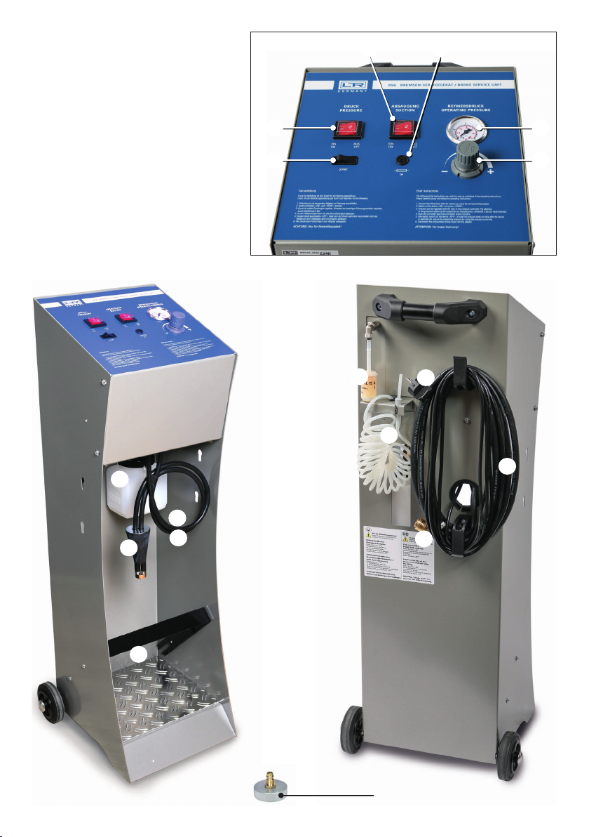
– Place the original brake fluid container in the tray provided for this purpose. (11)
– Take off the cap from the original brake fluid container. Immerse suction and return hoses (10) with the filter at the
end into the brake fluid container until the bottom is reached. Adjust the rubber cone and press it into the opening
of the container.
– Mount the required or supplied B-adapter (B 611) on the connection (16) of the filling hose (15). (additional
adapters available)
– Hold the filling hose (15) with the B-adapter over a catch container.
– Switch on the unit, set the switch (2) to the <ON> position and press and hold the <START> button (1) until the
pump begins to feed. Catch the exiting brake fluid.
NOTE:
• The unit is set to an operating pressure of 2 bars at the factory.
• This pressure can be retained for flushing.
– As soon as the brake fluid exits bubble-free, release the <START> button (1), switch off the unit and set the switch
(1) to <OFF>.
– Disconnect the B-adapter from the filling hose (16).
– The unit is now ready for operation on the vehicle.
– Dispose of the caught brake fluid properly.
6. Extracting brake fluid (only device BSG 03_230A)
– Connect brake service unit to power supply.
– Switch on the extraction unit of the chariot with ON/OFF switch (3).
– Hold end of spiral hose (14) in vehicle reservoir. Check filling level of catch container (7) during extraction (If
necessary, dispose of the brake fluid properly).
– After completing extraction, switch off the extraction unit with ON/OFF switch (3).
– Disconnect power supply of the Brake Service Unit.
7. Changing brake fluid on vehicle
CAUTION:
• The safety precautions in the section „Point 4 Safety instructions“ must always be
strictly adhered to. Before beginning work, be sure to observe the information on the
maximum filling pressure and special working instructions of the vehicle manufacturer.
The pressure regulator (6) is set to an operating pressure of 2 bars at the factory.
– Supply the unit with the voltage (230 VAC).
– Remove the sealing cap from the reservoir in the vehicle.
– Mount a suitable B-adapter on the reservoir.
– Connect the filling hose (15) to the mounted B-adapter.
– Set the switch (2) to the position <ON>.
– Press and hold the <START> button (1) until the pump builds up pressure and continues running automatically.
– Pulling the pressure regulator knob (6) unlocks it. The operating pressure can then be set in accordance with the

- 6 -
manufacturer‘s information by turning the knob. Then lock the knob again by pressing it.
– Now the prescribed quantity of brake fluid can be removed at the brake cylinders.
– After changing the brake fluid, switch off the unit by setting the switch to <OFF>.
– The unit generally depressurizes itself. However, if the pressure has been reduced during operation, a residual pressure
remains in the unit. This is released by turning the pressure regulator (6) all the way to the „Minus“ position.
– Disconnect the filling hose (15) and remove the B-adapter.
– Close the vehicle reservoir again with the sealing cap.
For vehicles with an electrohydraulic brake (Mercedes/Toyota), it is temporarily necessary to reduce
the working pressure of the BSD (Brake Service Device). Here the device automatically switches off.
By holding down the start button, the vehicle can continue to be ventilated in this case. In this situati-
on, however, the automatic shut-off is bypassed with an empty drum.
8. Changing original brake fluid container
– The unit is equipped with an automatic switch-off function when the original brake fluid container is drained.
– The unit must be bled again when the container is replaced.
– The procedure for bleeding is the same as that described in Point 5 Initial operation.
9. Technical data and accessories
Pressure gauge measuring range: 0…4 bar
Power supply: 230 VAC
Filling hose: with quick coupling 3 m
Dimensions: 300 / 400 / 1000 mm (W/D/H)
Weight: 21 kg
Operating, ambient
temperature range:
0...45 °C
Air humidity: 40 - 60 %
Fuse values: 230 V = T1A
IP protection class: IP20
NOTE:
For information on evaluating the brake fluid, see the section on brake systems in the current Leiten-
berger catalogue.
• EBT 01 Electric brake fluid tester (100124 for DOT 4).
• EBT 03 Electric brake fluid tester (100128 for DOT 3, DOT 4, DOT 4 Plus and DOT 5.1).
• EBT 03_USB Electric brake fluid tester (100127_1, with USB connection)
• EBT 06 Electric brake fluid tester (100134 for DOT 3, DOT 4 and DOT 5.1).

- 7 -
10. Troubleshooting
Problem Cause Remedy
Pump suction failure
Original brake fluid container empty Replace original brake fluid container
Pressure regulator set to „MINUS“ Set correct operating pressure
Suction hose kinked Remove kink, replace defective
hose
Filter suction hose clogged Clean or replace filter
Pump fails to run on automatically Original brake fluid container empty Replace original brake fluid
container with new one
No power supply at unit Fuse defective Replace fuse
No voltage on the on-board socket Fuse defective or ignition not
activated
If necessary replace the fuse, insert
the ignition, check the socket.
Suction failure Filter clogged Replace filter
11. Available spare parts
ET 293.1 121189_1 Filling hose with European coupling
ET 445 121475 Plastic catch container, 1 liter
ET 520 111860 Fuse holder with fuse
ET 569 111615 Start button
ET 570 111616_1 Mains switch
ET 573 111619 Gauge, range 1 to 4 bar
B 611 100611_1 Adapter with K-nipple
ET 619 111665 Pump 230 V
ET 589 111634 Pressure regulator
ET 624 121566 Pressure switch
ET 633 111678 Suction and return hose 750 mm with strainer and stepped rubber
ET 720 111766 Spiral hose (extraction)
ET 1003 111559_1 Filter (extraction)
12. Storage conditions, disposal
Storage conditions
– Store the device in a clean and dry environment.
– Keep the device out of reach of unauthorized persons.
Disposal
– The old device must not be disposed of with normal household waste.
– The device has to be disposed of according to national regulations (e.g. ElektroG in Germany).

556956/10/2018/BSG03-03A
Subject to technical alteration. 2018/11
This manual suits for next models
3
Table of contents
Other LTR Service Equipment manuals