Gram Precision Z3 User manual

QUICK START
GUIDE
1 x 220V/7.5VDC 1A mains adapter.
1 x Z3 Display.
Accompanying documentation.
PACKAGING
Z3
1
1
2
2
1
2

BUTTON FUNCTIONS
DISPLAY COMPONENTS
Shows the weight of the object(s) on the platform of the weighing device.
In HOLD mode, the reading flashes to indicate the last stable weight recorded and not the actual weight on the platform.
Measurement unit used to indicate the weight.
Stable weight reading. This indicates that the weight on the platform is not fluctuating.
It flashes to indicate that there is movement on the platform.
Indicates net weight.
The net weight is the actual weight on the platform, minus the tare.
It is only displayed if a tare has been used.
Negative sign.
This reading may be negative if a tare is activated (in “preset tare” mode) or to indicate a problem when setting it to zero.
Tare activated.
The reading flashes to indicate that “normal tare” mode has been activated.
A “preset tare” is retained even after the weight is removed from the platform of the weighing device.
Battery mode. Not connected to the mains.
PRESS ONCE PRESS TWICE PRESS AND HOLD
“Clear”: Clears the tare, cancels “hold” mode
and resets the total accumulated weight. Switches the display on/off.
Tare: This may be “normal tare” or “preset
tare” depending on the operating mode
selected.
If the reading is less than five divisions, the
display will automatically be set to zero
instead of a tare.
If there is a preset tare in the memory and
there is nothing on the platform, pressing this
button deactivates the tare.
This switches the tare mode from “preset
tare” to “normal tare”.
The default operating mode is “preset tare”.
When the tare function is activated, this switches the
display from net weight to gross weight every time
the button is pressed. When net weight mode is
switched on, “NET” will appear on the LCD display.
HOLD mode activated/deactivated
.
Access to the options and default settings
menu.
Prints the weight indicated on the LCD display. Prints the weight indicated on the display and
adds it to the total.
Prints the total accumulated weight and
resets the reading to zero.

KEYBOARD AND DISPLAY
Switches the device on/off.
If the button is held down for more than 2 seconds, it acts as an off/on switch.
Tare a container or object
Place an object or container on the platform and wait until the display indicates a stable reading.
Press the tare key and check that tare is shown on the display; the reading will be “0”.
If a “preset tare” (1) is being used, the reading will be negative when the object is removed from the platform.
Printing a simple ticket
Place an object on the platform and wait until the display indicates a stable reading.
Press the print key to print out a ticket showing the gross and net weights and the tare (2).
Printing a ticket with an accumulated total
Place an object on the platform and wait until the display indicates a stable reading.
Press the print key twice to print the reading shown on the display and add it to the accumulated weight (2).
Press the print button twice to add and print each of the next weights. At the end of each detail sum, the total
accumulated sum appears in the display.
If the print key is held down for more than 2 seconds, the accumulated total is printed and the
ticket stops printing. This completes the accumulated total operation and deletes the accumulated total from the
memory. The display is ready to start another ticket.
Hold mode
Press the key twice to activate hold mode.
Once an object has been weighed and removed from the platform, the previous reading flashes on the display.
If another object is placed on the platform, the display will show the new reading in the same way.
To deactivate this function, press the same key twice.
(1) See reference manual to modify this tare function.
(2) Optional printer; not included with the device.
BASIC FUNCTIONS

MENU MAP OF SCALE CONFIGURATION
FILt
NOT-F
ONOFF AUTO
30N
OFF 1h 1h30N
ONOFF
NOYES
ONOFF
ONOFF
S-NODE
192009600 38400 57600
COntPRInt StAb
unIt
NAx
dIv
dEC
2ErO InI-0
NAx-0
0-trA
0-dIS
NOYES
100OINL
OFFON
NOYES
21 5 10 20 50
Hg
g O2 lb
21 3 4
OFF
ON
F-CntwEIGh r-Cnt
ForN Pr6Pr4 PC-0 USb rd3
CAL
NOYES NOYES
NOYES NOYES
NOYES
TARE
A-TAR
T-STB
NEnu
A-OFF
Bl-On
BEEP
TARE
hOLd
LOCk
rS232
SCALE
tIcKt
dISp
WILES
bAudr
ESC
validate the displayed
option
Go back without changes
Change to the next option
Factory setting

For enter the setup menu hold for 2 seconds the key . The display will show the message NENU for half a second
indicating that the display will show the menu options for setup the scale behaviour. In mode “menu”, the indicator buttons
act as navigation keys. The function for each key is shown on top of each button: ESC, , , .
Back to the previous menu level without save changes. Being at the main menu level, exit the mode “menu”
and backs to the weight indicator’s mode.
Moves to the next menu option on left direction. While editing a value, changes between the different input
values to choose.
Shows the current value for a parameter setting. While editing a setting, moves to the next possible value.
Since we change the parameter value by using keys and , clicking the key, we validate the new value.
When in “edition” mode (manual input, digit by digit, of a numeric value), one click on moves to the next
digit position. For validate the whole input value, double click the key or hold the key pressed for 2 seconds.
Moves to the next menu option on right direction.While editing a value, changes between the different input
values to choose.
In this menu, you will find the options that allow you to parameterize and perform the adjustment of the scale.
unit Unit : g, kg, oz, lb.
NAH
Max capacity of the scale. Enter the value including the decimal digits.
DIU
Division: The scale interval, or difference between two consecutive indicated values. Possible choices are 1,2,5,10,20 o 50.
dEC Decimal dot position.
2Ero Settings for Zero function.
InI-0 Initial zero setting at start (select Yes / Not).
NAH-0 Allows to select the limits of the semi-automatic zero setting device. Possible options are: MAX (allows
zero setting for any load under max capacity); OIML (follows OIML R76 rules).
0-trA Zero tracking ON / OFF.
O-dIs Shows zero indication into the display (Yes/Not).
CAL Menu options to perform the scale adjustment.
Scale adjustment -CAL-
You can access this menu right after power on the indicator by clicking at once keys and (a short pulse, not a
sustained pulse) while is running the LCD test displaying all the segments.
CALIB Perform the adjustment using a known weight. This function automatically sets the initial zero and the slope
factor for the scale span by using a known weight.
SETUP MENU OPTIONS AND SETTINGS
SCALE SETTINGS MENU -SCALE-

G-SET Gravity adjustment depending on geographic location of the scale:
G-COR Correction ON / OFF (you can decide whether activate the geographical adjustment).
OFSET Geographic location code (see table below).
OFSET Manual input (keyboard) of the initial zero (ADC counts).
SPAn Manual input of the scale span slope, 5 digits.
PrCAL Prints (or sends) a ticket with the current settings.
rESET Reset to factory settings..
ADCAL ADC span pre-adjustment. Only to be used at factory time using the correct load cell reference.
Scale adjustment -CALIB-
1. Empty the load receptor, then choose “CALIB” option.
2. The display will show the message “CAL 0” blinking, telling that the initial zero value acquisition is in process.
3. One time the initial zero value acquisition is done, put onto the load receptor the adjustment weight (the indicator
suggests a mass value for that weight, but you can put any weight with a known mass).
4. Input the weight value. Use the cursor keys for enter a value on each display digit and to move to the next or previous
position.
5. Once you enter the weight value, double click on key to validate. The display will show the message “-CAL- “blinking
while acquiring the adjustment value for the span slope of the scale.
6. Last, it will show the message “GEO “for a couple seconds, asking for the code of the geographical location where you did
the scale adjustment. The geographical location code is a numeric value from 0 (equator) to 31 (North / South pole). Choose
the needed value from the table below. Use the arrow keys and for change the value, validate by clicking the key.
7. Finally, it will show the message “SAVE” indicating that the scale adjustment is done and already recorded into the non-
volatile flash memory. The indicator exit the setup menu and go back to the weight indicator mode, displaying the weight
onto the load receptor.
If the automatic correction of the weight regarding to the geographical latitude and height (“G-COR” option) is set to ON,
the next time you power on the indicator, it will display the message “GEO” blinking, and the user will be asked to enter
the value corresponding to the geographical area where the scale is to be used. Once the user inputs the value for the
geographical area where the scale is placed, this value is recorded into the non-volatile memory and the user will not be
asked for it again.
The geographical area where the scale is located can be changed later by entering the setup menu NENU SCALE
CAL G-SET GEO G NN (where nn {0-31})
The automatic correction for gravity adjustment can be disable by entering to the setup menu NENU SCALE CAL
G-SET G-COR OFF

TABLE OF GEOGRAPHICAL ADJUSTMENT VALUES
Gram Precision S.L.
Travesía Industrial, 11 · 08907
Hospitalet de Llobregat · Barcelona (Spain)
Tel. +34 902 208 000 · +34 93 300 33 32
Fax +34 93 300 66 98
comercial@gram.es
www.gram-group.com
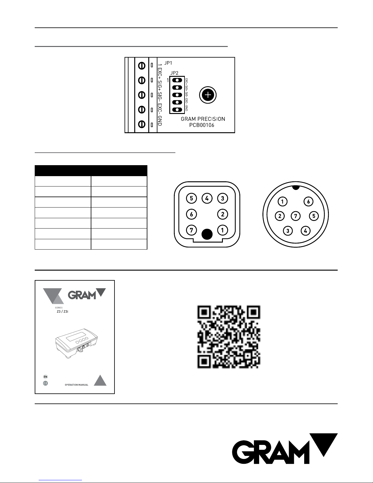
Nº PIN SIGNAL
PIN 1 SIG -
PIN 2 SIG +
PIN 3 MALLA
PIN 4 EXC -
PIN 5 SENSE -
PIN 6 EXC +
PIN 7 SENSE +
LOAD CELL CONNECTION
Option 1 : Indicator with direct cable connection
Option 2: Indicator with connectors
7 PIN HARTING MALE 7 MULTI-PIN MOBILE MALE
MORE INFORMATION
http://gram-group.com/wp-content/uploads/2016/12/MANUAL_Z3_2016_ENG_001.pdf
Download the full manual from the following link:
Table of contents
Other Gram Precision Accessories manuals


