Grandbeing EX0101-N343-000 User manual

User Manual
HDMI Extender
EX0101-N343-000
EX0101-N353-000

Important Safety Instructions
Notes
In case of any content change, we are sorry for no further notice.
Warnings
To reduce the risk of fire, electric shock or product damage:
1. Do not expose this apparatus
to rain, moisture, dripping or
splashing and that no objects
filled with liquids, such as vases,
shall be placed on the apparatus.
6. Clean this apparatus
only with dry cloth.
2. Do not install or place this unit
in a bookcase, built-in cabinet or
in another confined space.
Ensure the unit is well ventilated.
3. To prevent risk of electric
shock or fire hazard due to
overheating, do not obstruct
the unit’s ventilation openings
with newspapers, tablecloths,
curtains, and similar items.
4. Do not install near any heat
sources such as radiators, heat
registers, stoves, or other
apparatus (including amplifiers)
that produce heat.
5. Do not place sources of naked
flames, such as lighted candles,
on the unit.
7.Unplug this apparatus
during lightning storms or
when unused for long
periods of time.
8.Protect the power cord
from being walked on or
pinched particularly at
plugs.
9.Only use
attachments/accessories
specified by the
manufacturer.
10.Refer all servicing to
qualified service
personnel.

1
Table of Contents
Introduction....................................................................................................2
Overview...................................................................................................2
Features ...................................................................................................3
Package Contents ....................................................................................3
Specifications ...........................................................................................4
EX0101-N343-000.............................................................................4
EX0101-N353-000.............................................................................6
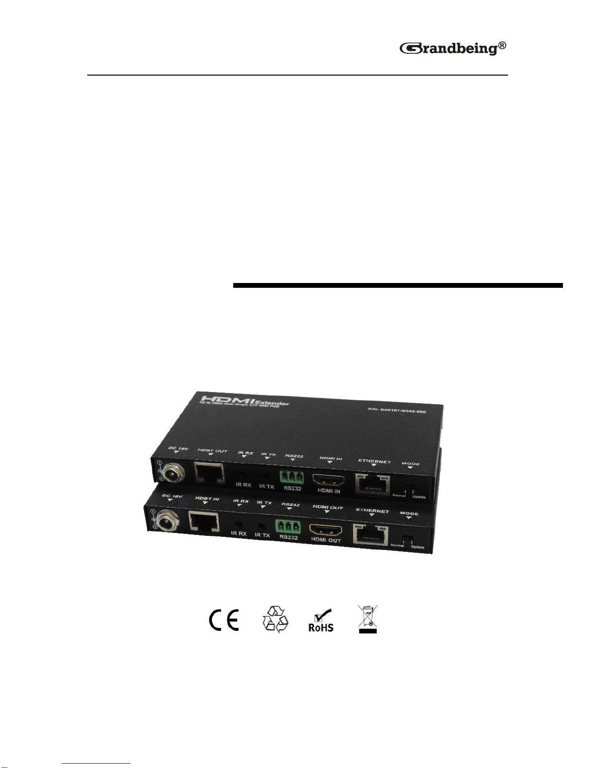
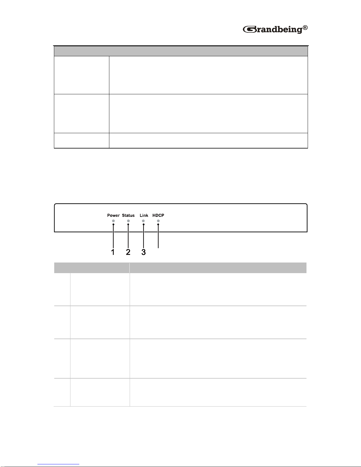
Panel ........................................................................................................8
EX0101-N343-000.............................................................................8
EX0101-N353-000...........................................................................10
Hardware Installation ..................................................................................14
Operations with IR and RS232....................................................................16
IR Control ...............................................................................................16
Scenario 1.......................................................................................16
Scenario 2.......................................................................................17
RS232 Control........................................................................................17
Scenario 1.......................................................................................18
Scenario 2.......................................................................................18
Troubleshooting...........................................................................................19
Product Service ...........................................................................................21
Maintenance...........................................................................................21
Provided Service ....................................................................................21
Mail-In Service........................................................................................21
Warranty.................................................................................................22
Warranty Limits and Exclusions..............................................................22
Glossary .......................................................................................................24

2
Introduction
Overview
EX0101-N343-000 (N343 for short) and EX0101-N353-000 (N353 for short),
a pair of slim HDMI extenders, are designed to extend HDMI signals up to
100 meters via a single CAT5e/CAT6 cable. N343 and N353 just need a
single power supply to power both devices via its bi-directional PoE function.
You can control the source from the sink's location or control the sink from
source's location via IR pass-through function. N343 and N353, easy to
install and space saving, offer solutions for home, office, digital entertainment
centers, control centers, conference rooms, school and corporate training
environments.

3
Features
Slim appearance and space saving.
Support bi-directional PoE.
Transfer bi-directional infrared control signal together with the HDMI signal.
Use a pair of N343 and N353 to extend HDMI signals without additional
settings.
Use a single CAT5e/CAT6 cable, following the standard of IEEE-568B, to
extend the transmission distance up to 100 meters.
HDMI 1.4 with 4K2K.
HDCP compliant.
Support RS232 ports for firmware upgrading or signal controlling.
Package Contents
1 x Transmitter EX0101-N343-000
1 x Receiver EX0101-N353-000
1x 18V 2A DC power supply
1 x Power cable
4 x Mounting ear
2 x IR emitter cable
2 x IR receiver cable

4
Specifications
EX0101-N343-000
Technical
Input
1 x HDMI IN
Input Signal
Type
HDMI 1.4 with 4K2K
Input
Resolution
Support
3840x2160/1080P/1080i/720P/576P
/480P/576i/480i
Input Video
Level
0.5-1.2 V p-p
Output
1 x HDBT OUT
Output Signal
Type
HDBT
Output
Resolution
Support
3840x2160/1080P/1080i/720P/576P/
/480P/576i/480i
Video
Impedance
100Ω
Maximum
Pixel Clock
297MHz
Operating
Temperature
32°F to 95°F (0°C to 35°C)
10% to 90%, non-condensing
Storage
Temperature
-4°F to 140°F (-20°C to 70°C)
10% to 90%, non-condensing
Power Supply
DC 18V 2A

5
Technical
Power
Consumption
N343 powers N353 with PoE: 13W for N343 and N353
N343 and N353 connected to power supplies: 5.5W for
N343
ESD
Protection
Human-body Model:
±8kV (Air-gap discharge)
±4kV (Contact discharge)
Surge
Protection
IEC 61000-4-4 (EFT) 40A (5/50ns); IEC 61000-4-5
(Lightning) 25A (8/20μs)
System
Requirements
HDMI equipped source devices
HDMI cables
HDMI equipped displays (TVs or monitors)
Industry standard CAT5e/CAT6 cables
Cable Specifications
It's recommended that straight-through Ethernet cables of T568B be
required.
Cable Type
Range
Supported Video
CAT5e/CAT6
100 m
1080p, 60 Hz 36 bpp
70 m
1080p 60 Hz 48 bpp
1080p 60 Hz 3D
4K2K 30Hz
CAT6a/CAT7
100m
General
Product
Weight
220g
Case
Dimension
(W x H x D)
190 mm x 95 mm x 138 mm
7.5'' x 3.7'' x 5.4''

6
Technical
Product
Dimension
(W x H x D)
135 mm ×14 mm ×77 mm
5.3'' x 0.6''x3''
Certification
CE, FCC, RoHS
EX0101-N353-000
Technical
Input
1 x HDBT IN
Input Signal
Type
HDBT
Input
Resolution
Support
3840x2160/1080P/1080i/720P/576P
/480P/576i/480i
Input Video
Level
0.5-1.2 V p-p
Output
1 x HDMI OUT
Output Signal
Type
HDMI: HDMI 1.4 with 4K2K
Output
Resolution
Support
3840x2160/1080P/1080i/720P/576P/
/480P/576i/480i
Video
Impedance
100Ω
Maximum
Pixel Clock
297 MHz
Operating
Temperature
32°F to 95°F (0°C to 35°C)
10% to 90%, non-condensing
Storage
-4°F to 140°F (-20°C to 70°C)

7
Technical
Temperature
10% to 90%, non-condensing
Power Supply
DC 18V 2A
Power
Consumption
N353 powers N343 with PoE: 12.2W for N343 and N353
N343 and N353 connected to power supplies: 7.6W for
N353
ESD
Protection
Human-body Model:
±8kV (Air-gap discharge)
±4kV (Contact discharge)
Surge
Protection
IEC 61000-4-4 (EFT) 40A (5/50ns); IEC 61000-4-5
(Lightning) 25A (8/20μs)
System
Requirements
HDMI equipped source devices
HDMI cables
HDMI equipped displays (TVs or monitors)
Industry standard CAT5e/CAT6 cables
Cable Specifications
It's recommended that straight-through Ethernet cables of T568B be
required.
Cable Type
Range
Supported Video
CAT5e/CAT6
100 m
1080p, 60 Hz 36 bpp
70 m
1080p 60 Hz 48 bpp
1080p 60 Hz 3D
4K2K 30Hz
CAT6a/CAT7
100m
General
Product
Weight
240g

8
Technical
Case
Dimension
(W x H x D)
190 mm x 95 mm x 138 mm
7.5'' x 3.7'' x 5.4''
Product
Dimension
(W x H x D)
135 mm ×14 mm ×77 mm
5.3'' x 0.6''x3''
Certification
CE, FCC, RoHS
Panel
EX0101-N343-000
ID
Name
Description
1
Power LED
On: N343 is powered on.
Off: N343 is powered off.
2
Status LED
Blinking: N343 works properly.
Off: N343 does not work properly.
3
Link LED
On: N343 and N353 are linked to each other.
Off/Blinking: Connection exceptions exist between
N343 and N353.
4
HDCP LED
On: HDCP video is being transmitted.
Blinking: No HDCP video is being transmitted.
4

9
Rear Panel
ID
Name
Description
1
Power
Connect to a power supply via a power adapter.
Note:
If N343 is connected to a power supply, N353 is
adapter free.
If N353 is connected to a power supply, N343 is
adapter free.
2
HDBT OUT
Connect to the N353 via a CAT5e/CAT6 cable.
3
IR RX
Connect to an IR receiver cable.
4
IR TX
Connect to an IR emitter cable.

10
ID
Name
Description
5
RS232
Used to connect to a computer to update firmware or
connect a RS232 device.
6
HDMI IN
Connect to a source device via an HDMI cable.
7
ETHERNET
Connect to a network access point, for example
connect a router to allow a network terminal
device attached to N353 (such as a computer) to
access the network.
Connect to a network terminal device, such as a
computer, which can access the network if N353
is connected to a network access point.
8
Mode
Normal:
N343 works properly.
RS232 signals can be transmitted
N343 cannot be updated.
Update:
N343 works properly.
RS232 signals cannot be transmitted.
N343 can be updated.
EX0101-N353-000
Front Panel
4

11
ID
Name
Description
1
Power LED
On: N343 is powered on.
Off: N343 is powered off.
2
Status LED
Blinking: N343 works properly.
Off: N343 does not work properly.
3
Link LED
On: N343 and N353 are linked to each other.
Off/Blinking: Connection exceptions exist between
N343 and N353.
4
HDCP LED
On: HDCP video is being transmitted.
Blinking: no HDCP video is being transmitted.

12
Rear Panel
ID
Name
Description
1
Power
Connect to a power supply via a power adapter.
Note:
If N353 is connected to a power supply, N343 is
adapter free.
If N343 is connected to a power supply, N353 is
adapter free.
2
HDBT IN
Connect to the N343 via a CAT5e/CAT6 cable.
3
IR RX
Connect to an IR receiver cable.
4
IR TX
Connect to an IR emitter cable.

13
ID
Name
Description
5
RS232
Used to connect to a computer to update firmware or
connect a RS232 device.
6
HDMI OUT
Connect to a sink via an HDMI cable.
7
ETHERNET
Connect to a network access point, for example
connect a router to allow a network terminal device
attached to N343 (such as a computer) to access
the network.
Connect to a network terminal device, such as a
computer, which can access the internet if N353 is
connected to a router.
8
Mode
Normal:
N353 works properly.
RS232 signals can be transmitted
N353 cannot be updated.
Update:
N353 works properly.
RS232 signals cannot be transmitted
N353 can be updated.

14
Hardware Installation
Warnings
Before the installation, disconnect the power supplies from all the
devices.
It's recommended that you do not connect or disconnect cables
from the N343 and N353 when they are powered on. To connect or
disconnect cables from N343 and N353, power them off first.
You must straight-through Ethernet cables of T568B and do not use
cross-over Ethernet cables.
Please connect and disconnect cables gently.
1. Connect the source (such as HD-DVD) to HDMI IN on N343 via an HDMI
cable.
2. Connect an IR emitter cable to IR TX and an IR receiver cable to IR RX on
N343.
3. Connect a sink (such as HD-LCD)to HDMI OUT on N353.
4. Connect an IR emitter cable to IR TX and an IR receiver cable to IR RX on
N353.
5. Connect HDBT OUT on N343 to HDBT IN on N353 via a CAT5e/CAT6
cable.
6. Connect all the devices to the power supplies and start the operations.

15
N343
TV Remote
DVD remote
N353
TV remote
IR receiver cable
IR receiver cable
IR emitter cable
IR emitter cable

16
Operations with IR and RS232
IR Control
IR pass-through function in N343 and N353 allows you to control the source
from the sink's location or control the sink from source's location.
Scenario 1
In this case, IR RX on N343 is connected to an IR receiver cable and IR TX
on N353 is connected to an IR emitter cable. You can control the TV on the
N343's location with the TV remote.
TV
Blue-ray DVD
HDMI
Ethernet
IR
N343
TV Remote
N353
TV remote
IR receiver cable
IR emitter cable

17
Scenario 2
In this case, IR TX on N343 is connected to an IR emitter cable and IR RX on
N353 is connected to an IR receiver cable. You can control the DVD-player
on the N353's location with the DVD remote.
RS232 Control
You can use a RS232 port on N343 or N353 to connect to a computer to
update firmware or connect a RS232 device to communicate with another
RS232 device on the other extender's side via a CAT5e/CAT6 cable.
TV
Blue-ray DVD
HDMI
Ethernet
IR
N343
TV Remote
N353
DVD remote
IR receiver cable
IR emitter cable

18
Scenario 1
Scenario 2
N353
N343
RS232
Ethernet
RS232 device
RS232 device
This manual suits for next models
1
Table of contents
Other Grandbeing Extender manuals

Grandbeing
Grandbeing EX0101-U30 User manual

Grandbeing
Grandbeing EX0101-XN52-000 User manual

Grandbeing
Grandbeing EX0101-U50 User manual

Grandbeing
Grandbeing EX0101-OP5 User manual

Grandbeing
Grandbeing EX0101-U52R User manual

Grandbeing
Grandbeing EX0101-N104 User manual

Grandbeing
Grandbeing EX0101-U32/U33 User manual

Grandbeing
Grandbeing EX0101-U52 User manual

Grandbeing
Grandbeing HDIP01 User manual

Grandbeing
Grandbeing EX0101-HE1 User manual