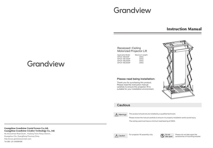
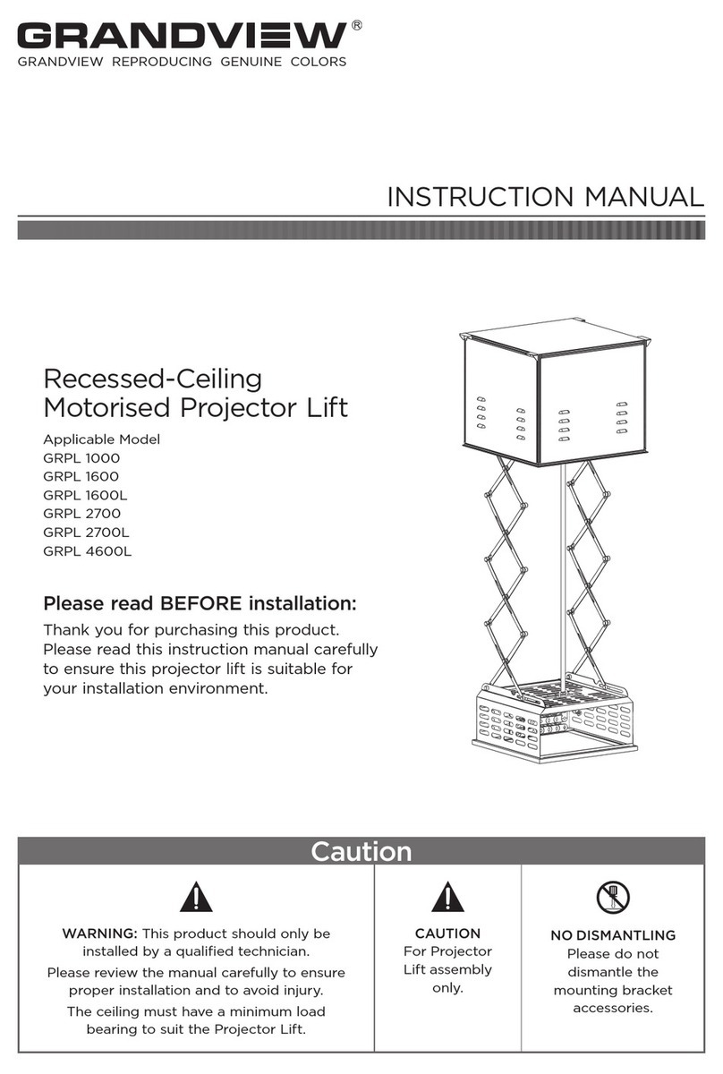
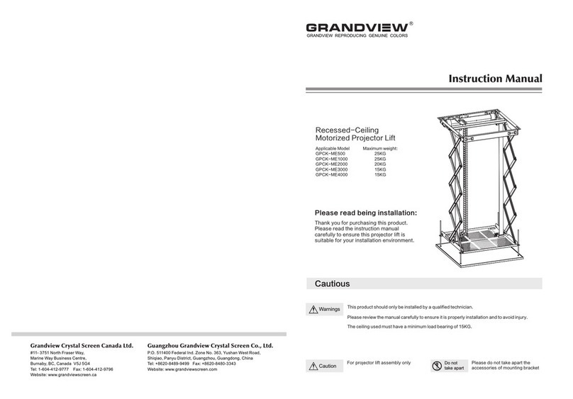
Grandview GPCD58 Series User manual

Telescopic rod projector lift installation manual
Model:GPCD58 Series
Grandciew Crystal Screen Guangzhou Co.,Ltd.
Guangzhou Jude Intelligent Audiovisua l Equipment Co., Ltd.
No.43 S, Guomao Ave. H ualong, Panyu, Guangzhou, Guangdong, P.R.C
http://www.grandviewscreen.com
After-sales service T el:0 20-84899499
Thank you for purchasing this product. Please read the manual carefully before use.
Please read the collection after reading for future reference.

Green label adjustment hole-the door shuttered
Yellow label adjustment hole-the door shuttered
as it closed(clockwise)
Figure 9
FAQ
The cause of the trouble The solutionTrouble
Line problem Contact factory or distributor
Motor heating protection
Layer board
Close the door shake
Open the door shake
Wait for motor cooling
The elevator is fully
installed but not
working properly
Remote control
doesn't respond
Positioning confusion
Bad reception/The signal block Restart the lift power supply
Positive and negative electrode of generator battery is
installed backward or the battery power is insufficient
The design of this product can be used without failure for many years, many problems are caused by simple things.
If something goes wrong, check out our simple fix list.If the problem continues, please contact the authorized dealer
or call the after-sales service number: 020-84899499-509
Check whether the battery is installed backward according to the
instruction. If the fault i s not remove d, please re place the ba ttery
Refer to picture 9 for a slight clockwise half turn
Refer to the yellow mark in picture 9 and turn it clockwise slightly for half a turn
Connect the power cord according to the instruction
The power cord is not properly connected
The adjustment screw becomes loose during transportation
Left and right corresponding door panel adjustment indication diagram:

1
Do not take apart the lift by yourself,
Please call a specialist to help you on
this when Fix and regulating job in needed
1.Please ensure the installation ceiling be secure enough to avoid falls, The loading capacity
must be 4 times of the projector lift and the projector.
2.Please tighten all the screws and check whether it become loose regularly, to ensure safety use.
3.Please do some regular maintenance.
A.When dirty mark there, please gave the lift a polish with a soft duster.
B.When dust there, please remove with soft brush.
4.Kindly suggest a specialist to manage this device, then ensure security and smooth use.
5.Please ensure the lift up and down via Remote control, no pulling with hands.
6.Always retract the lift to the ceiling after use.
7.Ensure the power outlet is connecting with grounding wire.
8.There is no need to add the lubricant to the motor. Do not regulate the motor by yourself, the motor
is already in the right position before delivery, Please call a specialist to help you on this when it is
in needed.
When the lift is fully lowered, the bottom
of the lift should be no less than 1.8 meters
away from the ground to avoid being touched
by children。
Please always retract the lift to the ceiling
after use, prevent the dust entering.
Please install the lift in the place with
stronger loading capacity, otherwise
accident may happen and falling risk
there.
Lower limitation
Upper limitation
Caution
Please do read the caution, incorrect
operation will cause accident and product
damage.

112
Components
GPAD64 Series Projector Lift
1.Control panel
2.Electric ceiling door
3.Ceiling bezel
4.Telescopic Arms
5.Projector mounting Bracket
Accessories
1pcA C 0 9 7 remote Certification 1pc Warranty Card 1pc
Manual 1pc4x25 Cross head screw 4pc 5x25Cross head screw 4pc
Hexagonal Adjuster 1pc
6x25Cross head screw 4pc
Safety rope 4pc
Φ20x10washer 4个
Projector mounting Bracket
Telescopic Arms
Electric ceiling
door
Ceiling bezel
Control panel
Picture 8
Remote control learning mode
Up
Stop
Down
Press up and stop together
1.Picture 8, when projector lift is under loading status, long press stop on the control panel within 5 seconds
after switched on. When number display screen flicker, this product is under learning mode.
2.Press up and stop on the remote control until the projector lift slight move upwards and downwards.
3.Test if the remote could control the product properly, if not, try to pair again.
GPAD58 Series projector lift remote control pairing notice:
This product has learning and pairing function. Please enable learning function when first use
remote to control the projector lift.
(This product has been paired and learned before EXW)
CONTROLLER G1
up
CAT6 CAT6 Dry contact RS-485
IN-220V
50Hz 80W
INPUT
HDMI2.0
stop Down Reset memory
Remote control backRemove the screw
and cover
Traction wire electronic
positioning setting button
Battery
Battery
1.Working temperature: - 20℃ to + 70℃
2. Battery: 2 pcs of RC2032 button battery
3.Requires replacement battery when given
signal weak
When remote control signal weak, please replace
it as following:
1.Remove screw and cover on the back of remote
2.Install battery in correct direction of positive and
negative pole according to picture.
3.Reinstall cover and screw
Remote control Notes
Battery installation:

3
10
Specification
760mm 760mm
Detail in Parameter List
Screw Rod Installation Size
740mm
453mm
800mm
800mm
φ10mm
Model Product size
GPCD5804
GPCD5809
760x760x590 550x580x240453x740 775x775
775x775760x760x860 550x580x240453x740
Mounting Hole Ceiling opening size Quantity of
Telescopic
Arms
4
4
Suggestion Projector
Size Range
(W*D*H)mm (W*D)mm (W*D)mm (W*D*H)mm
Front View Side View
Biggest negative heavy:25kg
775x775 mm
453x740 mm
800x800 mm
220V 50Hz
120W
W550XD580XH240 mm
( )
≤55dB
Running speed:1m/min
Operation accuracy:<2mm
Control mode: weak electric dry contact, 485 Control
Required smallpox height:H+50mm
Ceiling Hole Opening Size
Screw Rod Installation Size
Ceiling door Dimension:
Rated Voltage
Rated Power
Suitable for projector size:
Including wiring and lens
The noise
:
:
:
:
:
Model: GPCD58 Series
Front View
Rs485 Port Setting:
Bit Rate: 2400
Data bit: 8 bit
Odd check: N/A
Stopping position: 1
Hexadecimal control code:
UP:ff,ee,ee,ee,dd
STOP:ff,ee,ee,ee,cc
DOWN:ff,ee,ee,ee,ee
Some center console need setting address:ff,ee,ee,ee,aa
USB Serial Port (COM3) 属性
常规 端口设置 驱动程序 详细信息 事件
2400
8
无
位/秒(B):
数据位(D):
奇偶校验(P):
高级 A
()
…还原默认值(R)
1
无
停止位(S):
流控制(F):
取消
确定
常规 端口设置 驱动程序 详细信息 事件
Baud Rate: 2400
Data Bits: 8
Parity: 无
Stop Bits: 1
Flow Control:
Baud Rate:
位/秒(B) :
数据位(D) :
奇偶校验(P) :
停止位(S) :
高级 A
( )
…还原默认值(R)
取消
确定
无
流控制(F) :
Remote controller
Notice:
1.When connecting via RS232 or RS485, if any control fails, please switch two controlling cable.
2.Connecting Loop Resistance Tester should not be over 20Ω
3.Prohibit parallel line with strong interference source
UP
STOP
DOWN
Control button instruction
1.Press UP to lift
2.Press STOP to stop
3.Press DOWN to lower

(Installation diagram)
49
Central control RJ45 plug
wiring instruction
NO.1 --GND
NO.2--DOWN
NO.3--STOP
NO.4--UP
others maintain
Remote Localizer
When it is necessary to set the lower limit, open the electric double door. When the laminate reaches the ceiling,
press the pause button to use the keyhole on the back of the remote controlWhen the needle is inserted into the
blue light, the hanger will enter the preset state and reach the position required by the customer. Press the stop
button and insert the needle into the back of the remote control againWhen the small hole light is off and the
hanger moves slightly up and down once, the setting is completed.
This sink plate will be automatically lowered down
when the light is on.
Insert a needle into
the hole
light on enters preset
state
Central Control Instruction : requires a professional installation or contact us.
orange and white
orange
green and white
blue
blue and white
green
brown and white
brown
、
、
、
、
、
、
、
2
1
2
3
4
5
6
7
8
1 3 4 65 7 8
down stop up
Central Control box
RS-485 plug:7为+ / 8为-
5A 3 B
RJ45 wiring instruction
485-RJ
NO.7——join485A
NO.8——join接485B
45 plug
wiring instruction
others maintain
Rj45 plug
Rj45 plug
Rj45 plug
Concreted-Ceiling
Ceiling layer
Ceiling decoration frame
Projector Direction
(Note: Control panel opposite direction projector direction)
Installation
Installation instructions
This projector lift needs to be recessed into the ceiling,and this instruction takes the grille-ceiling
as the example. Please install the projector lift according to different application. The projector lift
needs to be recessed at the best viewing angle in order to improve the image. Take out all the parts
from the packaging and follow the installation instructions as below.
For the convenience and safety, please read this instruction manual carefully and choose a
installation according to your requirement.
*
安装时必须保证顶板保持水平,否则容易造成机械臂的损坏!
Warning: The top plate must be kept parallel when installing, otherwise it will cause damage to the lift.

5
8
Installation steps
1.determine the direction of the projector and the installation position, according to the size
of the opening in the ceiling layer.
Concrete base
Concrete base
Ceiling decorative layer
(Ceiling opening size diagram)
Projection direction
2.Punch the concrete base and install the Tapping screws.
Tapping screws
775mm
453mm
740mm
775mm
Angle adjustment
Electrical, product instructions
Control panel description
Up: Electric hanger rises
Stop: electric hanger stops
Down: electric hanger drop
Communication port: Category 6 network port
Dry contact: dry contact interface RS485: RS485 interface
Power input: power input interface
Fuse: F6. 3A 250V
Reset: long press the reset button to adjust the height
Memory: electric hanger memory position height
HDMI 2.0: 19+1 2.0 HD interface
Digital display: electric hanger current screw telescopic height
Rotate left and right ±3°
1.
2.
。
3.
Rotate left and right
Use a hex wrench to loosen the two screws on the front end.
As shown by the arrow in Figure 1, the universal joint can be
adjusted to the left and right by ±3°.
vertical up and down adjustment
As shown in Figure 2, use the hex wrench to loosen the two
screws on the left and right. The universal joint can be adjusted
vertically upward by 1° and vertically downward by 8°.
The installation foot adjustment
Use a hex wrench to loosen the screws on the mounting feet.
As shown in Figure 3, adjust the screws to the desired length
and retighten the screws.
figure 1
1° vertically upwards and 8° vertically downwards
Adjust the length of the mounting feet
figure 2
figure 3
CONTROLLER G1
up
CAT6 CAT6 Dry contact RS-48 5
IN-220V
50Hz 80W
INPUT
HDMI 2.0
stop Down Reset memory

67
Screw rod
Grille ceiling
Concrete base
screw nut
5.Install the decorative frame so that the decorative frame fits on the ceiling layer and the
installation is completed.
make the decorative frame fits on the ceiling layer
Grille ceiling
For the convenience of installation, the side plates of the cage can be removed first. After the installation is
completed, the installer can stand in the cage and reinstall the side panels. At this time, the side panels must
be turned over and installed.
If it is necessary to adjust the limit height due to the installation environment or the limitations of the site, it
must be adjusted by a special technician or call after-sales.
1. Lower the bamboo joint of the lift to the height suitable for the installer to install the projector, and remove
the mounting feet on the bamboo joint.
2. After the mounting feet are fixed on the projector, re-attach the projector and the mounting feet to the angle
adjuster and tighten the screws.
(Note: Be sure to confirm that the screws are securely locked, be
careful to prevent the projector from accidentally falling!)
Angle adjuster
Tighten the screws
projector mounting Bracket
Projector installation
3.After checking that the tapping screw is fixed, install the screw rod and fix it. (In order to
make the screw rod easier to pass through the lifter, we recommend that the end of the
screw rod be tapered, and the length between each two lead rods can differ by 10-20mm.
Concrete base
screw nut Cushion
screw rod
recommended to sharpen the end of the screw into
a taper that makes it easier to pass through the
screw hole of the lift
4.Lift the lifter to the height of the installation position by using the lifting equipment, and
pass the screw rod through the four holes of the lifter. Adjust the height of the lifter with the
screw nut so that it is flush with the height of the ceiling layer. Remove the excess screw rod.
Please note that you must touch the upper limit switch to stop the projector lift from rising!
The level above the electric lift must be adjusted to the level, Tilting can cause the electric hanger to
malfunction.
This manual suits for next models
2
Table of contents
Other Grandview Lifting System manuals
Popular Lifting System manuals by other brands

STS
STS DPC01-R500 operating instructions

Launch
Launch TLT260AT user manual

EZ-ACCESS
EZ-ACCESS Passport PL44SP3651 installation manual

IDEAL
IDEAL A-2200IEH-XR Installation, operation & maintenance manual

WITTUR
WITTUR WGG-29.1 operating instructions

Getinge
Getinge Arjohuntleigh Maxi Sky 1000 Instructions for use

WITTUR
WITTUR OL35E-NA Operating instruction

Astor-Bannerman
Astor-Bannerman Nivano CTe Owners Manual and Instructions for use

facelift
facelift spider ts26 Short-form operating instructions

ATD Tools
ATD Tools ATD-10141A owner's manual

Bishamon
Bishamon FP3500 Operation manual

Invacare
Invacare RPS350-1E user manual