Granit RMM 251 User manual

- 1 -
Version 1.1
Situation: December 2017
Wilhelm Fricke SE
Zum Kreuzkamp 7
27404 Heeslingen
Germany
www.granit-parts.com
+49 4281 712 -0
CV/Commercial Tyre Changer
Users Manual
Art. N° 7790400001
GRANIT RMM 251

- 2 -
Safety 3
Intended Purpose 3
General Safety Instructions 3
Danger Signs 4
Installation and Assembly 5
Installation Protocol 5
Unpacking 6
Accessories 6
Installation 7
Foundations Requirements 8
Electrical Connection 9
Use and Maintenance 10
Description of the Machine 10
Technical Specifications 11
Maintenance 11
User's Manual 12
Controls 12
Functional Test 13
Wheel Clamping 14
Beadbreaking –Tubeless Tyres 15
Demounting –Tubeless Tyres 16
Mounting –Tubeless Tyres 17
Beadbreaking –Tyres with inner Tube 19
Demounting –Tyres with inner Tube 19
Mounting –Tyres with inner Tube 20
Beadbreaking & Demounting of 3-segments Multipiece Wheel 22
Mounting of 3-segments Multipiece Wheel 23
Beadbreaking & Demounting of 5-segments Multipiece Wheel 24
Mounting of 5-segments Multipiece Wheel 25
Troubleshooting 26
Moving the Machine 26
Storage 26
Circuit Diagrams 27
Hydraulic Circuit Diagram 27
Electrical Circuit Diagram 28
CE Declaration of Conformity 29
Spareparts list 30
Warranty policy –Credits –Disclaimer 35

- 3 -
Intended Purpose
The RMM 251 tyre-changer is intended to be used for the mounting and demounting of truck, bus,
agricultural vehicle and earthmover tyres.
The GRANIT RMM 251 model is CE-certified.
This machine may only be used for the purpose for which it is designed by the manufacturer.
Any damage caused by improper operation is not covered by the warranty.
General Safety Instructions
Only properly trained and qualified personnel are allowed to use this machine.
Any modification and conversion work on the machine that has not been authorized by the manufacturer,
can cause significant damage to property as well as personal injury in which case the
manufacturer/supplier will not incur any liability.
The machine must only be used according to its intended use and prescribed handling.
Before and during mounting, it is mandatory to ensure that the tyre and rim fit together and are compatible
with each other (matching sizes, e.g. the diameter in mm or inch, etc.).
If disturbances occur during operation or during the work process, the power supplies of the machine
must be switched off before any technical intervention.
All electrical connection or clamping may only be carried out by a qualified electrician, taking into account
the requirements of the national electricians‘ authority and/or the relevant energy supply company.
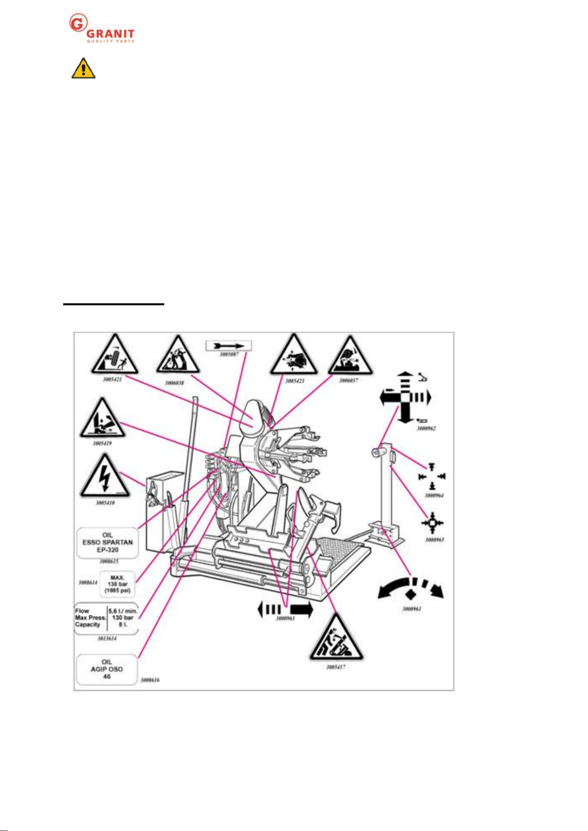
Since there is always a non-foreseeable residual risk when working with technical work equipment,
various self-explanatory warnings signs (triangle yellow/black) are affixed to the tyre-changer.
These warnings signal to the user a possible residual danger and should cause him to be particularly
mindful in order to avoid accidents at work and/or damage to the product to be worked on, i.e. the tyres
and rims.
The machine is only to be used by professionally skilled personnel who are aware of the safety
regulations.
In general, the operator should eliminate any possible residual risks from the outset through proper and
prudent behavior.

- 4 -
· Always use proper and appropriate equipment and tools.
· Wear suitable protective clothing and safety equipment (e.g. goggles, hearing protection, safety shoes,
etc.).
· Observe the specified information, instructions and technical data of the machine manufacturer or the
manufacturer of the product (tyres & rims) that is to be worked on.
Further special safety instructions are given in the individual chapters.
The Wilhelm Fricke SE does not assume any liability for damage caused by improper operation
and/or unpurposeful use of the tyre-changer.
Unauthorized interventions or changes to the machine are not permitted.
Danger Signs

- 5 -
CERTIFICATE OF FIRST COMMISSIONING OF THE
TYRE CHANGER
WARNING
To safeguard the warranty claims, the fully completed proof of the first commissioning
must be returned to the manufacturer.
•Tyre-changer properly unpacked and transported to the installation location
•User‘s manual read and understood
•Tyre-changer mounted on and bolted to level floor
•Power supply properly connected
•Machine assembled
•Basic settings checked and/or changed the and oil added
•Tyre-changer tested
No deficiencies have been found, so no objection can be made to the machine
being put into service.
Tyre changer model ________, Year of construction ______, Serial Nr. __________
Date of purchase ___________, Dealer´s address _____________________
_____________________
_____________________
_____________________
Date: _________________ Signature: _______________________________
User´s address _____________________
_____________________
_____________________
_____________________
Wilhelm Fricke SE
Zum Kreuzkamp 7
27404 Heeslingen
Germany

- 6 -
Unpacking
Unpack the device using the appropriate tools.
Carefully unpack the machine, check the correct condition and make sure that no parts are damaged or
missing.
Included in the delivery are:
Truck tyre-changer and mobile control unit
Bucket for mounting paste, paste-brush, gasket kit
Small tyre lever
Large tyre lever
Tyre mounting/bead pushing clamp
User‘s manual in English (on the outside of the packaging)
Accessories
7790400026 –Clamping jaw extensions from 47“to 56“
7790400027 –Alloy rim clamping protections (4 pc.)
500020463 –Bead pushing clamp LKW-LM for alloy rims

- 7 -
Installation
It is absolutely necessary to fill the machine with hydraulic oil and transmission fluid before it
is used!
The tension of the drive belt must be controlled! In case of non-observance, damages may
arise for which Wilhelm Fricke SE will not be held accountable or incur any liability!
•The RMM-251 commercial tyre changers are intended for professional use in workshops.
•Country and Company-specific safety regulations must be taken into account when selecting the
work area.
•When installing the machine, the distance requirements are to be taken into account according to
the drawing below.
•Operation of the machines in potentially explosive locations is not permitted.
•When selecting the location of the machine, observe the applicable regulations on work safety.
The floor in the room must not be uneven or damaged, so that the machine can be placed in a
stable position and the rollers of the tyre supporting platform can glide freely.
•If the installation is done outdoors, a roof must be installed to protect the machine from
precipitation.
•The ambient conditions must conform to the following guideline values:
Relative humidity from 30% to 95% without condensation; Temperature from 0 ° to 55 °c.
•The mobile control unit does not have a fixed place, but it must be ensured that the machine can be
seen at any time during operation.
All dimensions in mm.

- 8 -
Foundations requirements
The universal tyre changer must be placed on a level concrete (minimal quality: C20/25) floor of at
least 15 cm thick, in accordance to DIN 1045-2 (foundation). For explanation see the table as well as
the picture below.
If there is no flooring on site, foundations must be provided at least under the machine‘s
supporting/anchor points.
The surface must be flat in all directions. Floor inclinations (max. 0.25%) can be rebalanced with
appropriate washers, wedges or similar.
When de-/mounting wheels heavier than 1000 kg, it is necessary to attach the changer to
the ground by means of anchoring bolts.
The anchoring requires heavy-duty M16 anchor bolts, and an anchoring depth of at least 130mm.
If there is an additional flooring between the concrete and the machine, or if wedges and/or washers
have been used, then make sure to use accordingly longer anchor bolts.
Insert anchor bolts into every anchoring hole. The anchor bolts must be embedded at least 125 mm in
the concrete. (see figure below).

- 9 -
Electrical connection
Before any electrical connection is made, make sure that the mains voltage corresponds to the value
indicated on the voltage plate (380 v.-3 Ph.-50/60 Hz.).
Following conditions are to be met:
- It is essential to connect the machine to a good grounding network.
- The machine must be connected to a 30 mA fuse.
- The socket must be protected against overcurrent by means of fuses or a circuit breaker with nominal
values in accordance with the table below.
Power supply
Safety fuse
Switch
380 V. - 3 Ph. - 50/60 Hz.
16 A AM
16 A
Any work on the electrical system, even on smaller scale, must be carried out by professionally
qualified personnel.
Any damage resulting from failure to comply with these instructions will exempt the
manufacturer from any liability and result in the warranty being void.
Connect the changer to the power supply, press the main switch and make sure that the motor of the
hydraulic force unit is running in the direction of the arrow (fig. 6) Should it turn the wrong way round,
then have 2 phases inverted by specialized personnel.

- 10 -
Description of the Machine
1 –Lifting bracket 13 –Mechanical tool arm sled
2 –Chuck arm 14 –Mechanical tool arm
3 –Chuck 15 –Locking lever
4 –Platform 17 –Bead loosener disc
8 –Joystick 18 –Mounting hook
9 –Chuck switch 19 –Release pedal
10 –Chuck rotation pedal 22 –Clamping claws

- 11 -
When connecting the machine, pay attention to the indicated direction of rotation. In the case of
incorrect direction of rotation of the electric motor, damage can occur within a few seconds for
which the producer/supplier will not be held liable.
Technical specifications
Model
RMM 251
Hydraulic motor power
1,5 kW
Rotation motor power
1,8 kW
Max. clamping diameter
14“ to 56“
Max. wheel width
1065mm / 42“
Max. wheel diameter
2300mm / 91“
Max. wheel weight
1500 kg
Weight
770 kg
Power supply, V/pH/Hz
400/3/50
Max. noise level
< 70 dB (A)
Maintenance
Warning!
No maintenance work will be started until the machine plug is disconnected from the mains.
For the correct operation and longer durability of your tyre-changer, the following instructions must be
observed:
1) Lubricate the following parts on a regular basis after careful cleaning:
- the joints of the chuck
- the guide of the mechanical tool arm
- the slide plate.
2) Regularly grease the chuck arm‘s lifting cylinder and joint using the grease nipples (cf. Fig. J).
Use a common grease.
3) Regularly check the oil level in the Hydraulic power unit. There is a dipstick under the oil tank cap. If
necessary, refill with oil of the following variety: Esso Nuto H 46 or equivalent varieties (e.g.: AGIP OSO
46, SHELL TELLIUS OIL 46, MOBIL DTE 25, CASTROL HYSPIN AWS 46, CHEVRON RPM EP
HYDRAULIC OIL 46, BP ENERGOL HPL, GRANIT HLP 46 210HLP46 GEB20).
4) Periodically check the oil level in the gearbox when the chuck-arm is lowered to the stop. The oil must
always be visible in the sight glass on the gearbox housing when in lowest point. If necessary, refill with
oil of the following variety: Esso Spartan EP 320 or equivalent (e.g.: AGIP F1 REP 237, BP GRX P 320,
CHEVRON GEAR COMPOUND 320, MOBIL GEAR 632, SHELL OMALA OIL 320, CASTROL ALPHA
SP 320, GRANIT HLP 32 210HLP32 GEB20).
Note.: If the oil has to be replaced in the Hydraulic force unit or in the gearbox, both containers are
provided with drain screws.

- 12 -
The mobile control unit with the operating elements
(Fig. c) makes it possible for the operator to choose
the most convenient workspot, depending on the
phase of the operation. On this mobile control unit are
all the necessary controls:
In position [a] the joystick (8, fig. c) lifts the chuck arm,
in position [b] it lowers it. In position [c] it approaches
the tool carrier sled and the movable platform towards
the chuck, in position [d] it moves away from it.
Note: In order to be able to keep these positions better,
it should be noted that a hole in the protection of the
control handle is present at the height of the “c”
position of the joystick.
The switch (9, fig. c) pressed upward opens the arms
of the chuck (clamping). If it moves downwards, it
closes the arms of the chuck (release).
The two-way pedal (10, fig. c) makes it possible to
rotate the chuck in one direction or another depending
on the side you’re pressing down, as indicated by the
arrows on the pedal. Both rotations can be done at two
different speeds. Just press the selector (12, fig. 6/b)
in position 1 for low speed and in position 2 for high
speed.
On the tyre changer, following features are also
present: the pedal (19, fig. D), the handle (15, fig. D)
for tipping the tool carrying arm (14, fig. D) from the
working position to the "out of operation" position and
vice versa.
In the drawing (B/8) The various working positions (A,
B, C, D) are displayed, to which will be referred in to
the following operations’ manual. By working on the
indicated positions, the operation becomes more
precise, faster and safer for the operator.
Operating instructions
Controls

- 13 -
Controls check
Before you start working with the tyre-changer, go through the following checks to make sure
it works correctly.
Attention: For the controls described below, position the tool arm in the "out of service"
position. Therefore, first press the pedal (19, fig. D) to tilt the arm into this position.
WARNING! Face away from the tool arm while it
is being "unlatched".
1) Pull the joystick (8, fig. C) upward (a): the chuck arm
(2, fig. A) must rise. Press the joystick downwards (b):
the chuck arm must lower itself.
WARNING! Lowering the chuck carrying arm
creates potential injury situations. Therefore,
always work at the place mentioned in the
instructions’ manual and remain out of reach
of the various working arms.
Press the joystick to the left (c): the tool arm sled and
the mobile platform (13, fig. D) must move towards the
chuck (3, fig. a). Press the joystick to the right (d): the
tool arm sled and the mobile platform must move away
from the chuck.
2) Pull the switch (9, fig. C) upwards: the arms of the
chuck (3, fig. A) must open up. Press the switch
downwards: the arms of the chuck must close.
WARNING! The opening and closing of the
chuck creates potential pinch points.
Therefore always work at the point mentioned
in the instructions’ manual and remain
outside the range of the chuck.
3) Press the two-way pedal (10, fig. c) on the right:
the chuck (3, fig. A) must turn clockwise. Press the
two-way pedal on the left, the chuck must turn
counter-clockwise.
4) Check the proper operation of the hydraulic circuit:
pull the switch (9, fig. c) all the way up until the arms
of the chuck are completely open. Hold the switch in
this position and check whether the manometer on
the chuck’s rotation base indicates a pressure of 130
bar (± 10% tolerance).
If the read-out value is not in this range, the
changer must not be used.

- 14 -
Clamping the tyre
Place the mobile control unit in working position B.
1) Place the tool arm (14, fig. D) in the "out of
operation" position.
2) Use the joystick to move the moving platform (13,
fig. D) away from the chuck and roll the wheel (in
vertical position) on to it.
WARNING! This process can be very dangerous!
Do this by hand only if you are absolutely sure that
you can keep the wheel in balance. For heavy and
particularly large wheels it is essential to use
suitable lifting equipment, e.g. the GRANIT Wheel
Trolley, part. N° 76000076.
3) Also use the joystick to lift or lower the chuck arm
until the chuck (3, fig. A) is aligned with the rim center
point.
4) with the clamping claws (22, fig. A) in the closed
position, bring the wheel to the chuck using the
mobile platform. Then press the switch (9, fig. c) to
open the chuck and clamp the rim from the inside in
the optimal position, which must be selected
depending on the rim type, as illustrated in the figures
E/1-E/2-E/3-E/4-E/5-E/6. Clamping of the central
flange is always regarded as the safest method.
Note: For wheels with a (non-central) rim well, the
wheel must be clamped so that the rim well faces the
side opposite the chuck (cf. fig. E/1).

- 15 -
Beadbreaking –Tubeless Tyres
WARNING! Do not hold your hands on the
tool when you bring it back to the working
position. There is a danger it being crushed
between the tool and the wheel.
7) Press the lever (19, fig. g) and twist the tool
by 180° until it snaps into place automatically.
8) Place the mobile control unit in working
position D. Repeat the operations described
previously in points 5 and 6 to demount the
second bead.
1) Clamp The wheel on the chuck as described above
and make sure that the tyre is completely vented.
Bring the mobile control unit to working position C.
2) Lower the tool arm (14, fig. f) into the working
position until it is locked into the locking cone.
WARNING! Always make sure that the arm is
properly engaged and locked onto the sledge.
3) Use the joystick to position the (chuck and) wheel
so that the rim edge nearly touches the bead breaking
disk (Fig. f).
WARNING! The disk must not press on the rim, but
on the tyre bead.
4) Rotate the chuck and the wheel and at the same
time move the disk backwards; the disc should follow
the rim profile as far as possible.
5) Proceed until the first bead is completely separated.
To facilitate the process, apply lubricating paste or a
soap solution to the bead and the rim edge while the
wheel is turning.
WARNING! To avoid any danger when lubricating the
beads, rotate the wheel CLOCKWISE when lubricating
on the outside, and COUNTERCLOCKWISE when
lubricating on the inside.
The more the tyre sticks to the rim, the slower the
pression by the disc must be exerted on the tyre.
6) Move the tool arm (14, fig. f) away from the rim horn.
Unlock the tool arm’s locking cone and lift the arm into
the "out of operation" position, twist the tool head it and
lock it in the second working position (Fig. g).

- 16 -
Demounting –Tubeless Tyres
The demounting of tubeless tyres is possible in two
ways:
1) If the wheel presents no difficulties with regard to
demounting, continue after the bead removal by pressing the
disk on the wheel until the two beads are detached from the
rim (cf. Fig. h).
2) If the wheel is a super single or is particularly hard and
therefore cannot be processed as described in point 1, the
hook tool must be used. Proceed as follows:
-Move the tool arm to the outside of the wheel.
Move the mobile control unit to working position C.
-Rotate the wheel and move the hook tool towardw it at the
same time, pushing it between the rim and the bead until it is
firmly anchored to the bead (see fig. I).
-Move the rim about 4-5 cm away from the tool to prevent the
bead from slipping away from the tool.
-Move the hook tool outward until the red reference point is
near the rim edge.
Move the mobile control unit to working position B.
-Insert the lever between the rim and the bead (17, fig. I) to
the right of the tool.
-Hold the lever down and lower the wheel until the rim edge
has a distance of approximately 5 mm from the hook tool.
-Rotate the wheel counterclockwise, holding down the lever
until the bead is completely demounted.
-Move the tool arm into the "out of service" position and move
it to the rear side of the wheel (cf. Fig. L).
Move the mobile control Panel to the working position D.
-Twist the hook tool by 180 °, insert it between the rim and
the bead (cf. fig. L) and process until the bead is at the height
of the front rim edge while rotating the wheel.
-Move the rim approximately 4-5 cm away from the tool to
prevent the bead from slipping away from the tool.
Move the mobile control unit to working position C.
-Move the hook tool until its red reference point is
approximately 3 cm inside the rim.
-Insert the lever between the rim and the bead (17, fig. I) to
the right of the tool.
-Hold the lever down and lower the wheel until the rim horn is
at a distance of approximately 5 mm from the hook tool. Then
rotate the wheel counterclockwise until the bead is completely
removed.

- 17 -
Mounting –Tubeless Tyres
14) Move away the tyre by means of the rolling
platform.
15) Take the wheel down.
Note: If the tyre allows it, the process can be
accelerated by mounting both beads at the same
time:
- Proceed as described in point 1, 2, 3, 4, but not
only the first bead but with both beads set behind
the rim clamp (cf. Point 4).
- Lift the rim with the rear wheel and rotate 15-20 cm
in the anti-counterclockwise (pliers in 10 o'clock
position), and mount both beads.
- Then proceed as described in points 10, 11, 12, 13,
14, 15 of this section.
The mounting of tubeless tires can be done with the disk or with
the hook tool. If the wheel has no particular difficulty, you can
use the disk. Otherwise it is essential to use the hook tool.
MOUNTING WITH THE DISC
1) If the rim has been taken down from the chuck, it must be
reclamped as described in the section "CLAMPING THE
TYRE".
2) Lubricate the tyre beads and the rim with mounting paste or
a soap solution..
3) Attach the rim clamp to the rim of the wheel as shown in
Figure M.
WARNING! Make sure the rim clamp is firmly attached onto
the rim.
Move the mobile control unit to working position B.
4) Place the tyre on the platform and lower the chuck (note that
the rim clamp always remains at the highest point) to attach the
first bead to the rim clamp.
5) Lift the rim with the suspended tyre and rotate it 15-20 cm
counterclockwise. The tyre is now positioned slantingly on the
rim.
Move the mobile control Panel to the working position C.
6) Place the disk against the second bead of the tyre and rotate
the chuck until the wheel clamp has reachet the lowest point (6
o'clock position).
7) Remove the disk from the wheel.
8) Remove the rim clamp and reinstall it in the same position (6
o'clock) on the outside of the second bead (cf. fig. N).
9) Rotate the chuck clockwise by 90 ° until the wheel clamp is
in the 9 o'clock position..
10) Move the disk forward, up to 1-2 cm beyond the rim edge,
but always keep about 5 mm distance from the rim. Start the
clockwise rotation and make sure that the second bead starts
to slide into the rim bed after a 90°rotation.
11) When the assembly is finished, remove the tool from the
wheel, put it in the "out of operation" position and remove the
rim clamp.
12) move the platform under the vertical axis of the wheel.
Move the mobile control Panel to the working position B.
13) completely close the clamping claws of the chuck and
release the wheel while supporting it so that it does not fall.
WARNING! This process can be very dangerous! Do this
by hand only if you are absolutely sure that you can keep
the wheel in balance. For heavy and particularly large
wheels it is essential to use suitable lifting equipment.

- 18 -
17.
MOUNTING USING THE MOUNTING HOOK
1) Follow the procedure as described in points 1, 2, 3, 4, 5 of
the previous chapter (assembly with the bead breaker disk).
2) Put the tool arm in the "out of operation" position and
position it inside tyre to allow it to snap into place again.
3) Make sure the hook tool is positioned on the side.
Otherwise, press the lever (15, fig. D) and twist it by 180°.
Put the mobile control unit in position D.
4) Insert the mounting hook until its red reference point is
aligned with the outer edge of the rim, at a distance of 5
mm (cf. fig. O).
Put the mobile control unit in position C.
5) Make a visual inspection to see if the tool is correctly
positioned, and correct its position if necessary. Then turn
the chuck clockwise until the rim clamp is in the lowest
position (6 o'clock position). The first bead must then be
pulled into the rim.
6) Remove the rim clamp.
Put the mobile control unit in position D.
7) Remove the mounting hook.
8) Bring the tool arm to the "out of operation" position, move it
around the outside of the tyre and then reengage it in
locked position.
9) Twist the the mounting hook for 180° (15, fig. D) so as to
have it facing the second bead.
10) Position the rim clamp at the lowest position (6 o'clock
position) outside the 2nd rim edge (Fig. N)
Put the mobile control unit in position C.
11) Rotate the chuck clockwise by approximately 90° (until the
rim clamp are in the 9 o'clock position).
12) Insert the mounting hook until its red reference point is
aligned with the outer edge of the rim, at a distance of 5
mm (cf. fig. O).
Then start to rotation clockwise and make sure that the
second bead begins to slide into the rim bed after a rotation
of approximately 90°. Continue until the rim clamp is in the
lowest position (6 o'clock position). Now the second bead
should be mounted as well.
13) Continue as described in points 11, 12, 13, 14, 15 of the
Chapter „Assembly with the disk“ to correctly finalize the
mounting of the wheel onto the rim.

- 19 -
Beadbreaking –Tyres with inner Tube
WARNING: When deflating the tyre, first unscrew the nut that fixes the valve to the rim,
so the valve can loosely be pulled inside the rim and is not locked during the bead breaking.
For the rest, the bead breaking procedure is the same as described for the tubeless tires. In this case,
however, the pushing by the bead breaker disk must be interrupted as soon as the bead is released to
avoid damaging the valve and/or the inner tube.
Demounting –Tyres with inner Tube
11) Move the hook tool so that its red reference
point is about 3 cm inside the rim.
12) Insert the lever between the rim and the
bead, to the right of the hook (cf. fig. Q).
13) Hold the lever down and lower the wheel
until the rim horn has a distance of approximately
5 mm from the hook tool. Then twist the wheel in
the opposite counterclockwise until the bead is
completely removed from the rim.
Move the mobile control unit to working position C.
1) Tilt the tool arm (14, fig. D) into the "out of operation"
position and move it to the frontside of the wheel and re-lock
into its working position.
2) Rotate the chuck and at the same time insert the hook tool
(18, fig. D) between rim and bead until the bead is raised onto
the tool.
3) Move the rim approximately 4-5 cm from the hook tool to
prevent the bead from slipping away from it.
4) Move the hook tool outward until the red reference point is
near the rim edge.
Move the mobile control unit to working position B.
5) Insert the lever between the rim and the bead (cf. fig. P) to
the right of the tool.
6) Hold the lever down and lower the wheel until the rim edge
is at a distance of approximately 5 mm from the hook tool.
7) Rotate the wheel in counterclockwise, holding the lever
down, until the bead is completely demounted.
8) Move the tool arm into the "out of operation" position and
reposition it on the rear side of the wheel. Lower the chuck
until the tyre is pressed against the moving platform, moving
the latter outwards, you’ll create sufficient space to pull out
the tube.
Move the mobile control unit to working position D.
9) Move the the tool arm to the rear side of the wheel and twist
the tool 180°, then bring the arm into the working position.
Insert the tool between the rim and the bead and process until
the bead is at the height of the front rim edge (during the
operation it is advisable to rotate the wheel
contempraneously).
10) Move the rim approximately 4-5 cm away from the tool to
prevent the bead from slipping away from the tool.
Move the mobile control unit to working position B.

- 20 -
Mounting –Tyres with inner Tube
1) Place the tool arm in the "out of service" position. If the rim
has been removed from the chuck, it must be clamped again, as
described in the section "CLAMPING THE WHEEL". Note: If the
wheel has an inner tube, the rim must be arranged in such a way
that the opening for the valve is at the very bottom (in the 6
o'clock position).
2) lubricate the tyre beads and the rim with a soap solution or
mounting paste.
Move the mobile control unit to working position B.
3) Place the tyre on the platform and lower the chuck (make sure
that the rim clamp always remains at the highest point) to attach
the first bead to the rim clamp.
4) Lift the rim with the suspended tyre and rotate 15-20 cm in the
counterclockwise. The tyre then attaches slantingly to the rim.
5) Place the tool arm in the "out of operation" position, move it to
the rear side of the tyre and secure it.
6) Make sure that the hook tool is positioned towards the rim.
Otherwise, press the lever (15, fig. D) and twist the tool head
180°.
Move the mobile control unit to working position D.
7) Move the hook tool until its red reference point is aligned with
the outer edge of the rim and has a distance of 5 mm from it (cf.
Fig. s).
Move the mobile control unit to working position C.
8) Make a visual inspection to see if the tool is correctly
positioned and correct its position if necessary. Then turn the
chuck clockwise until the rim clamp is in the lowest position (6
o'clock position). By than, the first bead must then be mounted.
Remove the rim clamp.
Move the mobile control unit to working position D.
9) Pull the hook tool out of the tyre.
10) Place the tool arm on the "out of operation" position, move
to the frontside of the wheel and re-lock it in this position.
11) Twist the tool (15, fig. D) 180°.
Move the mobile control unit to working position B.
12) Rotate the chuck until the valve opening is at the bottom (6
o'clock position).
13) Move the moving platform (4, fig. A) under the wheel and
lower the chuck until the wheel touches the platform. Move the
platform outward to create space between the tyre and the rim in
which the inner tube can be inserted. Note: The opening for the
valve can be in asymmetric position in relation to the rim center.
In this case, the hose must be arranged and introduced as shown
in Fig. T. Insert the valve into the opening and secure it with its
nut.
14) Position the tube in the rim well.
This manual suits for next models
1
Table of contents