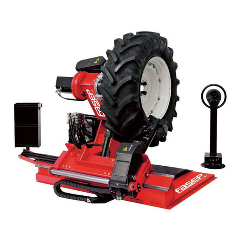
Fasep RGU2671.G User manual

Original notice
User’s manual
RGU2671.G
DIESEL
This product complies with the provisions of the
European Directive in accordance with Directive
2006/42/EU on the merge of the laws of the Member
States relating to machinery and the work rights.

Original notice –User’s manual
2
1. INTRODUCTION................................................................................................... 4
Area of use ......................................................................................................... 5
Guarantee........................................................................................................... 5
Guarantee conditions........................................................................................ 6
2. SECURITY ............................................................................................................. 7
Safety instructions ............................................................................................. 7
Security devices ................................................................................................. 8
Warnings............................................................................................................. 8
3. CHARACTERISTICS ............................................................................................. 11
4. RECEPTION......................................................................................................... 12
5. INSTALLATION................................................................................................... 13
Positioning........................................................................................................ 13
Fixation ............................................................................................................. 13
Ventilation ........................................................................................................ 14
Exhaust ............................................................................................................. 14
Electrical connection ....................................................................................... 15
6. IDENTIFICATION................................................................................................ 17
7. OPERATIONAL AREA ......................................................................................... 21
8. OPERATING CONTROL ...................................................................................... 22
9. USE ..................................................................................................................... 23
Starting and unfolding .................................................................................... 23
Tire disassembling........................................................................................... 24
Tire assembling................................................................................................ 25
Folding and stopping....................................................................................... 25
Adjustments ..................................................................................................... 26
Long inactivity .................................................................................................. 26
10. MAINTENANCE .................................................................................................. 27
Program............................................................................................................ 27
“TB” part............................................................................................................ 28
“BOX” part......................................................................................................... 30
Spare parts list ................................................................................................. 34
11. TROUBLESHOOTING ......................................................................................... 35
12. IN CASE OF FIRE................................................................................................. 38

13. END OF LIFE ....................................................................................................... 38


Original notice –User’s manual
3
14. CONTACT ........................................................................................................... 38
15. APPENDICES....................................................................................................... 39
16. EC DECLARATION OF CONFORMITY................................................................. 44

Original notice –User’s manual
4
1.INTRODUCTION
Read this manual thoroughly because it contains all the necessary information for
model identification, installation, use and maintenance of this product under
conditions that meet safety standards. Failure to do so may result in personal
injury or property damage.
Keep this manual within reach of the product as it is an integral part of it. In case
of resale, this manual must be sent to the buyer.
This manual is considered read and should be made available to the personnel
who use the product.
Keep the serial number in this manual to ensure product traceability in case of
failure, spare parts request, resale or even theft. Note this number on a separate
sheet that is kept in a safe place.
Proper maintenance, constant care and control are essential for proper
operation, optimum performance and durability of the product. For this reason,
it is important to note regularly all the work and the various maintenance done
on the product and to respect all that is presented in this manual.
All information, illustrations and specifications in this manual are based on the
latest data available on the date of publication. We reserve the right to modify this
manual at any time without prior notice.
This manual and its contents are the property of © Fasep 2000, it is forbidden to
copy or reproduce it in any form whatsoever, in whole or in part without our
prior written consent.
Serial number:

Original notice –User’s manual
5
Area of use
This product is designed for professional use only which requires its use. Any
other use is contrary to the "normal" use of this product. The manufacturer
declines all liability for material damage or personal injury resulting from non-
normal use, the risks being the responsibility of the user. "Normal" use implies
compliance with the rules written in this manual.
This product must be used, maintained and repaired by qualified persons trained
on this type of product. Always observe the accident prevention regulations and
the general regulations on safety and health at work. The manufacturer declines
all responsibility in case of material damage or personal injury resulting from a
modification of the product without our agreement.
Guarantee
The product is delivered ready to use after satisfying technical tests. It is
guaranteed for 12 months from the delivery date. The guarantee is only applied
if the administrative conditions and the recommendations of installation, safety,
use and maintenance contained in this manual are respected.
The manufacturer, through this guarantee, undertakes to freely substitute the
parts deemed to be defective after a factory inspection according to our
conditions.
The guarantee is limited to construction defects only. It excludes all liability for
material damage or personal injury. It will cease if the device has been damaged,
altered or disassembled.
No return is permitted without prior authorization. Any costs incurred as a result
of a call for which the manufacturer is not responsible shall be borne by the
customer.

Original notice –User’s manual
6
Guarantee conditions
The guarantee does not cover:
Damage due to natural or exceptional disasters.
Accidental damage to third parties.
Damage caused by frost.
Damage resulting from the use of additional accessories not original or not
recommended.
Normal wear and tear of components.
In any case, the damage resulting from an installation, operation, use or
abnormal maintenance of the device, in any situation whatsoever.
The guarantee will lapse and no recourse will be possible, in case of:
Non-compliance with the installation rules of the device and specifically:
oIN CASE OF IMPACT DUE TO INCORRECT HANDLING.
Failure to comply with the recommendations and warnings indicated in this
manual and specifically:
oIF CHANGES TO THE SAFETY BODIES.
oIN CASE OF USE GREATER THAN THE RECOMMANDED CAPACITY OF THE
DEVICE.
oIN CASE OF MAINTENANCE FAILURES.
Repairs or manipulations done by unauthorized third parties on the bodies or
operations listed in this manual.
The guarantee does not cover:
The cleaning of the device and its operating components.
The routine maintenance related to normal wear and tear of the appliance.
In case of any guarantee claim or for any intervention under guarantee, it will be
requested in advance: the proof of purchase and the serial number of the device.
These elements attest to the fact that the device is covered by the contractual
period.
The finding of a damage under guarantee does not systematically entail the
replacement of the device nor the extension of its guarantee, which is left to
the discretion of © Fasep 2000.
In case of refusal of guarantee, the decision will be motivated and explicitly
supported by a report done by a professional: the repairs will then be the subject
of an estimate.
For any objection to this refusal decision, the owner of the compressor may, at
his own expense, done a second opinion.

Original notice –User’s manual
7
2.SECURITY
Safety instructions
Read this manual carefully.
Do not use the device without prior training.
Keep the device out of the reach of children.
Never disassemble or modify the device in any form, in particular safety
systems.
Do not operate the device beyond its limits.
Always have your device repaired by our or authorized technicians.
Never use or intervene on the device in case of excessive fatigue or under
the influence of drugs, narcotics or any other substance reducing alertness.
Always keep the device and its area of use clean and free of greasy or slippery
substances.
Never pour liquid directly onto hot surfaces or electrical parts.
Never cover the ventilation areas of the device.
Never use a battery other than the recommended one.
Do not breathe generated air or exhaust gases. Make sure that the exhaust
hose is properly installed.
Never swallow the liquids used on this device.
During use:
oWear fitting body clothing, safety shoes, protective gloves and noise
protection. Avoid wearing jewelry.
oAlways open the side door and rear doors of the van.
oNever open the compressor panels.
oIn case of an emergency or suspected or detected malfunction,
immediately press the emergency stop button.
oDo not open filler or drain caps.
After use, wait until the device has cooled completely and empty the air
under pressure.
For maintenance:
oPress the emergency stop button.
oCheck that the device is switched off.
oWear protective gloves and goggles.
oUse only suitable equipment.
oUse only original spare parts.
oDo not use corrosive, flammable or volatile products for cleaning.

Original notice –User’s manual
8
Security devices
Magneto-thermal switch for protecting the pump motor: located inside
the power station, it intervenes in case of a motor overheat, avoiding its
deterioration.
Maximum pressure valve: rated at 180 BAR plus or minus 5%, it limits the
maximum pressure on the oil-hydraulic circuit ensuring the correct
operation of the installation.
Piloted check valve with double sealing: it avoids the fall of the mandrel in
the event of breakage of the oil-hydraulic circuit.
Check valve on the mandrel opening line: located inside the rotating
connector, it avoids a possible fall of the wheel due to accidental breakages
of the oil-hydraulic circuit.
Emergency stop.
Gasoline supply cut-off.
Warnings
HOT SURFACE
Never touch hot areas during and immediately after operation. Wait a few
minutes for the complete cooling.
MOVING PARTS
Do not insert any part of the body or object into moving parts.
Always ensure that the guard and panels are present and secured.

Original notice –User’s manual
9
RISK RELATED TO PRESSURIZED FLUIDS
Always check that the connections are tight and that the hoses are properly
connected.
After use and complete cooling of the compressor, empty the air under pressure.
RISK OF ELECTRIC SHOCK
Never open the electrical cabinet door or the motor housing.
Never use the device with wet hands or feet.
Never touch electrical parts.
AUTOMATIC START-UP
Never intervene on the device without completely stopping it.

Original notice –User’s manual
10
RISK OF CRUSHING
Several different stickers signal a risk of crushing.
Move as far as possible from areas where there is a risk of crushing.
Verify that no living being or object can be crushed.
Always wear safety shoes and protective gloves.

Original notice –User’s manual
11
3.CHARACTERISTICS
The TB126L is designed to the assembly and disassembly of tubeless tires for
heavy trucks, buses, civil engineering, agrarian, etc.
It is designed and manufactured to operate inside vans. All commercial vehicles
used for commercial transport (eg: MASTER, BOXER, CRAFTER, SPRINTER, DAILY,
etc.) with an appropriate transport capacity and dimensions.
Any other use of the device and/or any attempt to apply it to other types of wheels
is not permitted and is abusive and will therefore be considered illegitimate.
Maximum mass according to version: 779 kg
Maximum dimensions according to version (L x l x h): 1750 x 1150 x 1700 mm
Sound level at 1 meter: 85 dB (A)
Lombardini gasoline engine with liquid cooling: 14 kW / 2500 rpm
K30HUPP compression block: 5.5 kW / 900 rpm
Generator:
2.6 kVA single phase: 3050 rpm / 230 V single phase / 50 Hz
Or 6 kVA single phase: 3050 rpm / 230 V single phase / 50 Hz
Or 7 kVA three-phases: 3050 rpm / 230 V single phase / 380 V three-phases /
50 Hz
Rim diameter: from 14 to 26"
Maximum wheel weight: 700 kg
Maximum wheel width: 600 mm
Maximum wheel diameter: 1300 mm
Air flow rate: 45 m3/h
Nominal pressure: 12 BAR
Air tank capacity: 120 liters
Gasoline tank capacity: 23 liters
Safety valve: 15 BAR
Height of van loading plane: 400 –700 mm
Minimum van door width: 1200 mm
Minimum van door height: 1750 mm
Minimum van interior width: 1750 mm
Minimum van interior height: 1750 mm

Original notice –User’s manual
12
4.RECEPTION
Despite all checks done before delivery, there is always the possibility that some
anomalies occur during transport. For this reason, before commissioning, the
product must be inspected for damage.
In addition, it must be observed during the first hours of operation to detect any
anomalies.
Do not use your product in case of damage or malfunction detected, please
contact your dealer.
Handling
The device is supplied in a wooden box with pallet and must be moved with a
forklift truck.
Unpacking
1. Remove the packaging.
2. Ensure the integrity of the device and check for damage.
3. Do not leave the items of the package within the reach of children.
Keep the packaging during the contractual period of guarantee or for any possible
shipment. However, the various parts of the packaging must be recycled in
accordance with the legislation in force.

Original notice –User’s manual
13
5.INSTALLATION
Positioning
The place of installation must be chosen in accordance with the applicable safety
standards.
The installation is provided on vans whose dimensions are within the application
limits which make the device usable, as indicated in the technical characteristics
and explained in the following paragraphs.
The floor of the van must not be disjoint, its surface must be regular and equipped
with a wooden protection.
The working conditions must comply with the following parameters:
Ambient temperature between 0°C and 55°C.
Relative humidity from 30% to 95%.
Absence of potentially explosive sources (eg: gas tanks, chemical deposits,
etc.).
Sufficient ventilation.
Good overall cleanliness.
WARNING
Never place the battery or fuel tank within 30 cm of the exhaust pipe or any
heat source.
Fixation
The device must be attached to the van floor. It is advisable to contact us to avoid
possible damage to the mechanical / electrical / hydraulic parts under the floor.
The standard fixing points are shown in the sketches below.

Original notice –User’s manual
14
1. Check that the load capacity of the van is sufficient for the device weight.
2. It is advisable to use the supplied backplates for fixing to the floor (eg: a plate
with a thickness of 5 mm or more). It is necessary to fix the device to the 6
fixing points.
3. Use M10 anchor screws and check that the floor has sufficient strength.
Ventilation
Ventilation must be installed in the van and must have adequate opening to
ensure evacuation of heat. It must have a flow rate of 15 to 20% greater than the
amount of air required for the overall cooling of all installed components.
For a good ventilation of the system in a van, it is necessary to provide two
ventilation grids:
Air intake: 400 x 400 mm located at the height and in the axis of the air intake
of the compressor on the flywheel side of the compressor block
Air extraction: 2 solutions depending on use:
o400 mm x 300 mm being in the high position of the same side and in the
axis of the preceding one
oTo ensure optimum performance and performance, forced ventilation (eg:
fan motor) must be installed on the roof of the truck to extract heat if it is
used for more than 30°C outside.
Exhaust
In order to extract all the exhaust gases in a truck, an exhaust hose must be
installed.
The exhaust hose and exhaust pipe delivered with the device must be used. This
hose must take the shortest way to get out of the truck. To do this, it is obligatory
to drill a hole on the floor of the truck in order to cross with this hose through the
pipe.
DANGER
Ensure that the exhaust hose is not directed towards flammable materials.
Remove covers such as crates, containers, etc. Because the compressor
inevitably suffers damage during service. In addition, the risk of fire is very
high.

Original notice –User’s manual
15
Electrical connection
WARNING
Generators deliver electrical current when used.
Comply with current legislation and the installation and operating
instructions in this manual.
Never connect the generator directly to other power sources.
For all connections, use a flexible, resistant, rubber-sheathed cable conforming to
IEC 60245-4 or equivalent cables and ensure that they are kept in perfect
condition.
Connect Class 1 equipment to the generator using a PE cable (green/yellow); this
protective conductor is not required for Class 2 equipment.
Use only one Class 1 electrical device per electrical outlet.
Depending on the conditions of use (A, B or C), the following protective
measures must also be observed:
A - If the generator is not equipped with an integrated differential protection
device (standard version with neutral isolated from the grounding terminal):
-Use a device calibrated to 30 mA from each electrical outlet of the generator
(place each device within 1 m of the generator, protecting it from the weather).
-In the case of occasional use of one or more portable devices, grounding of
the generator is not necessary.
B -If the generator is equipped with an integrated differential protection device
(version with neutral connected to the ground terminal)
-In case of supplying a temporary or semi permanent installation, connect the
generator to earth *
C -Mobile applications (eg a generator installed in a moving vehicle)
The generators are designed to operate in a stationary manner. They can not be
installed on a vehicle or other mobile equipment without a study taking into
account the different installation and use specificities. Any use in motion is to be
avoided. If grounding is not possible, connect the grounding terminal of the
generator to the ground of the vehicle.
* To connect the generator to ground: attach a 10 mm² copper wire to the generator
grounding terminal and a 1 meter galvanized steel ground stake in the ground.

Original notice –User’s manual
16
Only connect suitable electrical receivers to the generator and whose total power
does not exceed the rated power of the generator. The electrical data of the
receivers, such as voltage and frequency, must correspond to those of the
generator. If the receiver information is missing, please ask the manufacturer.
Electrical installations of existing buildings are not permitted.
Never touch exposed cables or disconnected connections.
Never expose the equipment to liquid splashes or weather conditions or place it
on wet ground.
If there is any doubt about the installation, call us.
Choice of connection cables
Observe the sections and lengths recommended in this table when installing the
system or when using extension cords.
SECTION CONSEILLÉE DE CÂBLE
Single-phase
Three-phase
Current intensity
10 A
16 A
32 A
10 A
16 A
Units
mm²
AWG
mm²
AWG
mm²
AWG
mm²
AWG
mm²
AWG
Cable
length
used:
1 to 50 m
4
10
6
9
10
7
1,5
14
2,5
12
51 to 100 m
10
7
10
7
25
3
2,5
12
4
10
101 to 150 m*
10
7
16
5
35
2
4
10
6
9
*This cable length is the maximum length allowed, it must not be exceeded.
Installation method: cables on cable tray or non perforated tablet / permissible
voltage drop: 5% / multiconductor / cable type: PVC 70°C (example: H07RNF) /
ambient temperature: 30°C.

Original notice –User’s manual
17
6.IDENTIFICATION
Global identification
A: “BOX” part
B: “TB” part
B
A
N

Original notice –User’s manual
18
“BOX” part
A: “HGV” reel
B: Filter regulator lubricator “FRL” (hidden)
C: “LV” reel
D: Air tank
E: Battery (hidden)
F: Gasoline jerrycan
C
N
A
B
F
D
N
E

Original notice –User’s manual
19
“TB” part
A: Trolley translation cylinder
B: Mandrel holder
C: Electric engine
D: Oil pressure gauge
E: Folding/unfloding cylinder
F: Hydraulic mandrel
G: Stand
H: Tools holder
B
E
N
C
N
D
N
F
H
G
N
A

Original notice –User’s manual
20
Mobile control console
The mobile control console allows to choose the most suitable working position.
A: Manipulator wheel assembly/disassembly
B: Emergency stop button
C:Manipulator for device handling and wheel locking/unlocking
D: Clockwise/counterclockwise wheel rotation pedal
Manipulator A
Up to lift the mandrel holder.
Down to lower the mandrel holder.
To the left moves the mandrel holder to the left.
To the right moves the mandrel holder to the right.
Manipulator C
Up to enter the device inside the van.
Down to take the device out of the van.
To the left to open the mandrel for locking the wheel.
To the right to close the mandrel for unlocking the wheel.
A
B
N
C
D
Table of contents
Other Fasep Tyre Changer manuals

Fasep
Fasep TOP AUTOMATIC 4.0 Operating instructions

Fasep
Fasep RGU-566 Operation instructions

Fasep
Fasep V585.2.U User manual

Fasep
Fasep RGU600E User manual

Fasep
Fasep RGU588E Installation and operating instructions

Fasep
Fasep V548.G4.U User manual

Fasep
Fasep RGU300.ECO User manual

Fasep
Fasep RASE.2234 User manual

Fasep
Fasep RGU 264 E Operation instructions

Fasep
Fasep RAE.2108 User manual
Popular Tyre Changer manuals by other brands

Bosch
Bosch TCE 5210 Repair instructions

Corghi
Corghi AGTT 1600A Operator's manual

HENNESSY INDUSTRIES
HENNESSY INDUSTRIES coats 9028E installation instructions

Ranger
Ranger R745 Installation and operation manual

Sealey
Sealey TC962.V2 instructions

Katool
Katool KT-810 Installation, Operation and Maintenance User’s Manual