M1.3.BT100-BT100M.NLFREN 28082018
8
NL
Elke dag:
• Reinig de machine eenmaal per dag na gebruik.
Eenmaal per week:
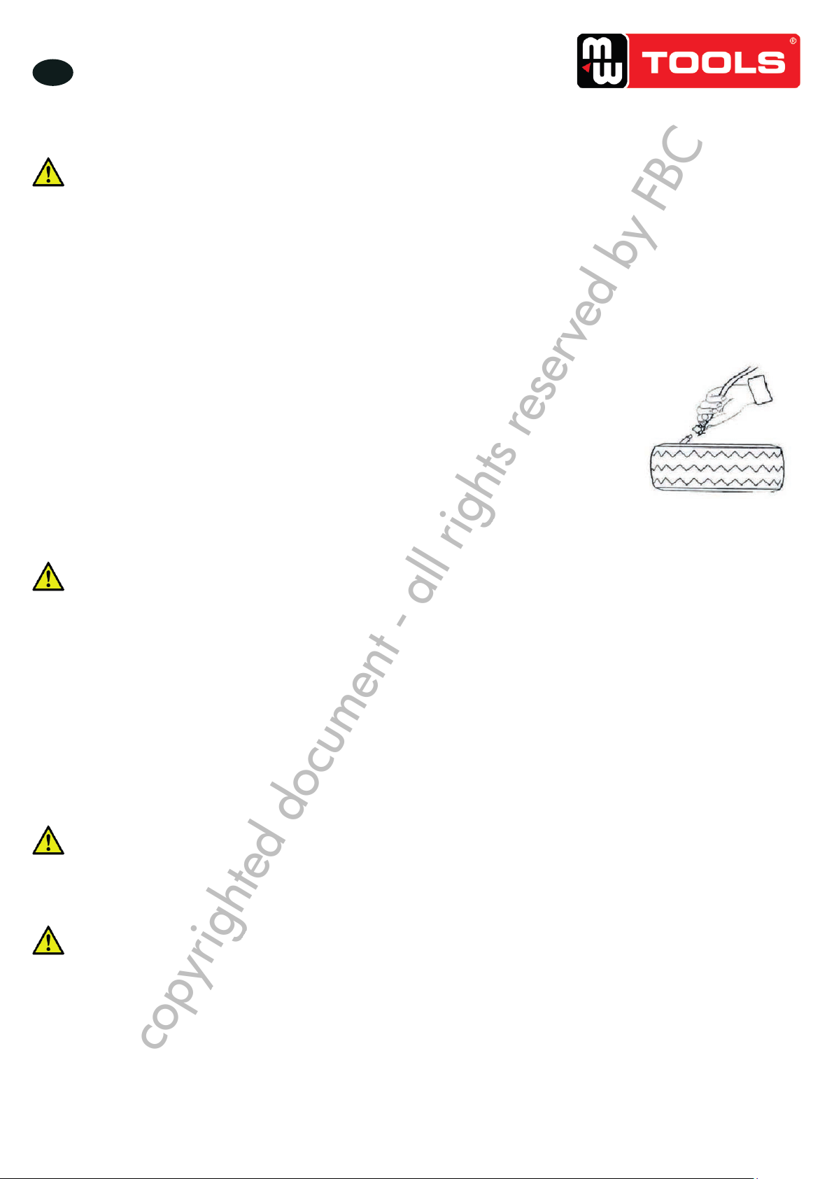
• Reinig het vuil op de draaitafel met dieselolie en smeer de glijbanen van de
spanklauwen.
Eenmaal per maand:
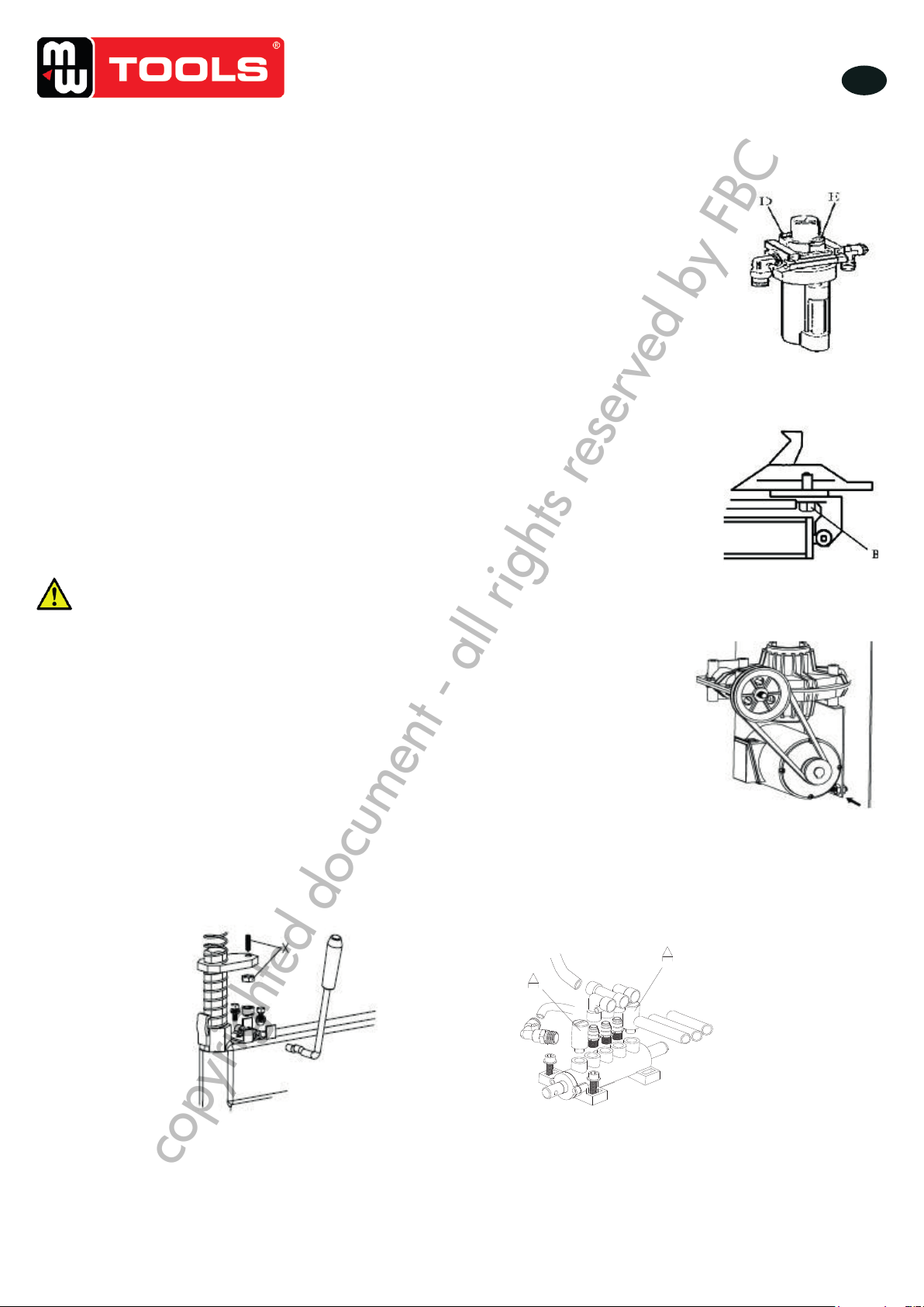
• Controleer het oliepeil in de olienevelaar. Vul bij indien nodig met SAE30 olie.
Draai de schroef (E) met een inbussleutel. Druk 5-6 maal op de voetpedaal van de
draaitafel of van de spanklauwen, en controleer of de olie in de olienevelaar druppelt.
Anders, regel de schroef (D), die de olie controleert, met een kleine schroevendraaier
(afb. 9).
Let op: Na de eerste 20 dagen gebruik, maak de spanklauwen vast door de
schroeven (B) op de draaitafel aan te draaien (afb. 10).
Let op:
Als de draaitafel kracht verliest, controleer dat de riem goed gespannen is:
• Verwijder het deksel aan de linkerkant door de schroeven los te draaien. Stel de twee
schroeven aan de motorsteun in, door een afstand te laten tussen de motorsteun en de
basis.
• Draai de spanschroeven van de riem vast (afb. 11).
AANDACHT!
Ontkoppel de machine van de stroomtoevoer en van de persluchtbron.
Let op:
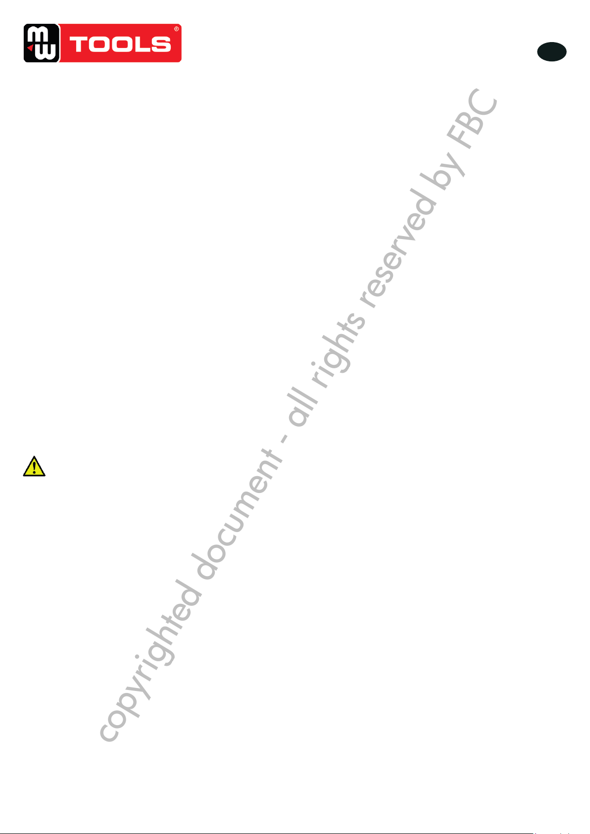
Als de verticale zeshoekige arm niet vergrendeld wordt, of als er geen 2-3 mm afstand is
tussen de demontage-/montagekop en de velg is, stel de zeshoekige slotplaat in zoals in
afbeelding 12 getoond, en regel de (X).
Let op:
Voor de betrouwbaarheid van de spanklauwen en van de hielbreker, ga als volgt te werk om
hun ventielen schoon te houden:
1. Verwijder het deksel aan de linkerkant van de behuizing, door beide schroeven los te
draaien.
2. Draai de dempers van het ventiel (A) op de voetpedaal voor het openen/sluiten van de
spanklauwen en van de hielbreker (afb. 13).
3. Reinig de dempers met perslucht, of vervang deze indien nodig.
.1211 . V201301
- 7 –
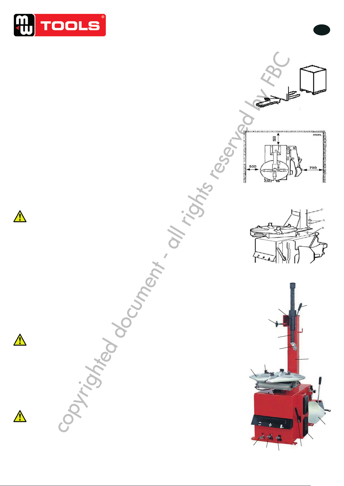
12. Moving machine:
Please use forklift to move the machine. Disconnect the tyre changer from the electricity power supply and
pneumatic power supply, lift the base board and insert the feet of forklift. Then mount the tyre changer machine to a
new position and fix it tightly.
Note: the place chosen for fixing the tyre changer must meet the safety regulation.
13. Maintenance:
Caution: only the professional persons can do the maintenance. To prolong the machine's life, maintain the
machine timely according to the manual. Otherwise, it will impact the reliability of the machine or even cause
injury to operator and others nearby.
Caution: before performing any maintenance, disconnect the tyre changer from the
electric power supply and pneumatic power supply, and tread the Jaws open and close
Pedal or Turntable Rotation Pedal for 3~4 times to evacuate all compressed air from the
machine. Damaged parts must be replaced by professional persons with the spare parts
provided by manufacturer.
- Clean the machine once every day after work. Clean the dirt on the turntable with diesel oil
once per week and lubricate the slides and clamps.
- Following maintenance must be done at least once per month:
Check oil level in Oil Fog Maker, please be filled with SAE30# oil if need.
Unscrew with hex wrench (E). Based on connection of compressed air, first to
tread Jaws open and close Pedal or Turntable Rotation Pedal 5-6 times, and
then check whether oil in Oil Fog Maker drops down a drip of oil. For
continuous operation, tread twice every time, drop down a drip of oil,
otherwise adjust the screw (D) that controlled oil enter with minus screwdriver.
(Fig 14)
Note: After the first 20 days of use, retighten the jaws with tightening screws (B) on the Turntable (Fig 15)
Note: in the event of turntable lose power, check to see if the belt is tight as follow steps:
Remove the left side cover by unscrewing the screws; adjust two screws located on the motor support, keep a
suitable distance between motor support and motor base; tight the screws for the belt tension.(Fig 16)
Caution: please disconnect the machine from electric power supply and pneumatic power supply.
Note: If Hexagonal Vertical Arm not be locked or not meet the requirement that 2-3mm from the bottom of
Mounting/demounting head to rim, please adjust Hexagonal Locking Plate, refer to Fig 17 and adjust the (X).
Afb. 9
.1211 . V201301
- 7 –
12. Moving machine:
Please use forklift to move the machine. Disconnect the tyre changer from the electricity power supply and
pneumatic power supply, lift the base board and insert the feet of forklift. Then mount the tyre changer machine to a
new position and fix it tightly.
Note: the place chosen for fixing the tyre changer must meet the safety regulation.
13. Maintenance:
Caution: only the professional persons can do the maintenance. To prolong the machine's life, maintain the
machine timely according to the manual. Otherwise, it will impact the reliability of the machine or even cause
injury to operator and others nearby.
Caution: before performing any maintenance, disconnect the tyre changer from the
electric power supply and pneumatic power supply, and tread the Jaws open and close
Pedal or Turntable Rotation Pedal for 3~4 times to evacuate all compressed air from the
machine. Damaged parts must be replaced by professional persons with the spare parts
provided by manufacturer.
- Clean the machine once every day after work. Clean the dirt on the turntable with diesel oil
once per week and lubricate the slides and clamps.
- Following maintenance must be done at least once per month:
Check oil level in Oil Fog Maker, please be filled with SAE30# oil if need.
Unscrew with hex wrench (E). Based on connection of compressed air, first to
tread Jaws open and close Pedal or Turntable Rotation Pedal 5-6 times, and
then check whether oil in Oil Fog Maker drops down a drip of oil. For
continuous operation, tread twice every time, drop down a drip of oil,
otherwise adjust the screw (D) that controlled oil enter with minus screwdriver.
(Fig 14)
Note: After the first 20 days of use, retighten the jaws with tightening screws (B) on the Turntable (Fig 15)
Note: in the event of turntable lose power, check to see if the belt is tight as follow steps:
Remove the left side cover by unscrewing the screws; adjust two screws located on the motor support, keep a
suitable distance between motor support and motor base; tight the screws for the belt tension.(Fig 16)
Caution: please disconnect the machine from electric power supply and pneumatic power supply.
Note: If Hexagonal Vertical Arm not be locked or not meet the requirement that 2-3mm from the bottom of
Mounting/demounting head to rim, please adjust Hexagonal Locking Plate, refer to Fig 17 and adjust the (X).
Afb. 10
.1211 . V201301
- 8 -
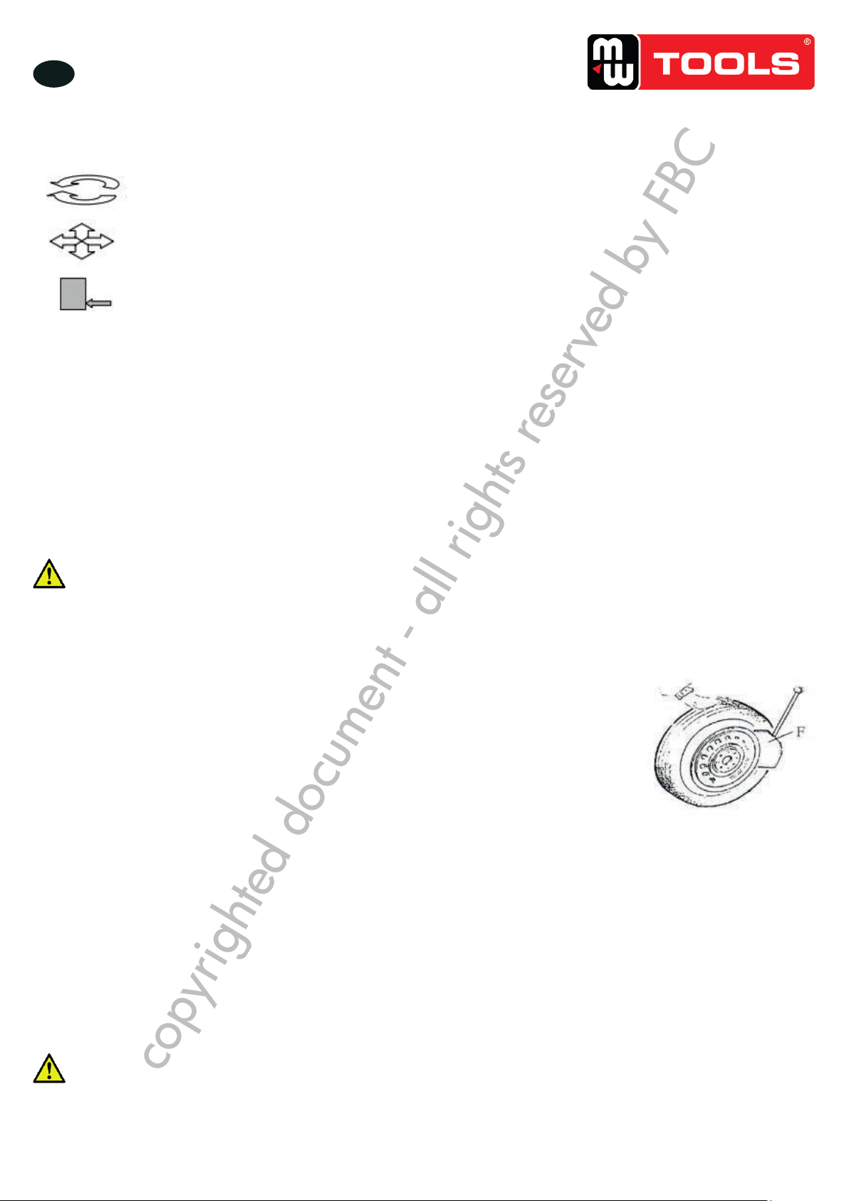
Note: In order to achieve the reliability of jaws and Bead Breaker shovel, operate as follows to keep their valves
clean:
1. Remove the left side cover of the machine body by unscrewing the two screws;
2. Loosen the valve Muffler (A) which belong to Jaws open and close Pedal and Bead Breaker Pedal; (Fig 18)
3. Clean the mufflers with compressed air, please replace it referring to the spare parts list if it is damaged. (Fig 18)
Fig 16 Fig 17
14. Trouble shooting table:
The turntable rotate just in one
direction or can’t rotate.
Replace the Reverse Switch
Check the motor cable or terminal
block wire;
Replace the motor if it was
broken.
Demount or fix the wheel, the
turntable can’t lock (spin with
wheel);
The jaws delay to open/close;
The turntable locks the rim
incorrectly.
Check all the parts on the air
network.
The clamping cylinder can’t work.
Replace the cylinder piston.
Broken washers of the chuck cylinder
The mounting/demounting head
always touch the rim during
operation.
The locking plate incorrectly adjust or
unqualified.
Screws on the chuck loose; the
Hexagonal Vertical Arm can’t be
locked by Locking Plate
Tighten the screws; replace the
Locking Plate.
The Bead Breaker Pedal and
Jaw open and close Pedal can’t
turn back to the original
position.
The Bead Breaker shovel
operates difficultly.
The washer on the Bead Breaker
cylinder is broken.
.1211 . V201301
- 8 -
Note: In order to achieve the reliability of jaws and Bead Breaker shovel, operate as follows to keep their valves
clean:
1. Remove the left side cover of the machine body by unscrewing the two screws;
2. Loosen the valve Muffler (A) which belong to Jaws open and close Pedal and Bead Breaker Pedal; (Fig 18)
3. Clean the mufflers with compressed air, please replace it referring to the spare parts list if it is damaged. (Fig 18)
Fig 16 Fig 17
14. Trouble shooting table:
The turntable rotate just in one
direction or can’t rotate.
Replace the Reverse Switch
Check the motor cable or terminal
block wire;
Replace the motor if it was
broken.
Demount or fix the wheel, the
turntable can’t lock (spin with
wheel);
The jaws delay to open/close;
The turntable locks the rim
incorrectly.
Check all the parts on the air
network.
The clamping cylinder can’t work.
Replace the cylinder piston.
Broken washers of the chuck cylinder
The mounting/demounting head
always touch the rim during
operation.
The locking plate incorrectly adjust or
unqualified.
Screws on the chuck loose; the
Hexagonal Vertical Arm can’t be
locked by Locking Plate
Tighten the screws; replace the
Locking Plate.
The Bead Breaker Pedal and
Jaw open and close Pedal can’t
turn back to the original
position.
The Bead Breaker shovel
operates difficultly.
The washer on the Bead Breaker
cylinder is broken.
Afb. 11
Afb. 12 Afb. 13
copyrighted document - all rights reserved by FBC