This Guide Outlines the Key Functions for a Smooth Operation:
A- Calibrating the CCD Camera White Point using Provided Black Media
B- Calibrating and Adjusting the Cutter’s Position
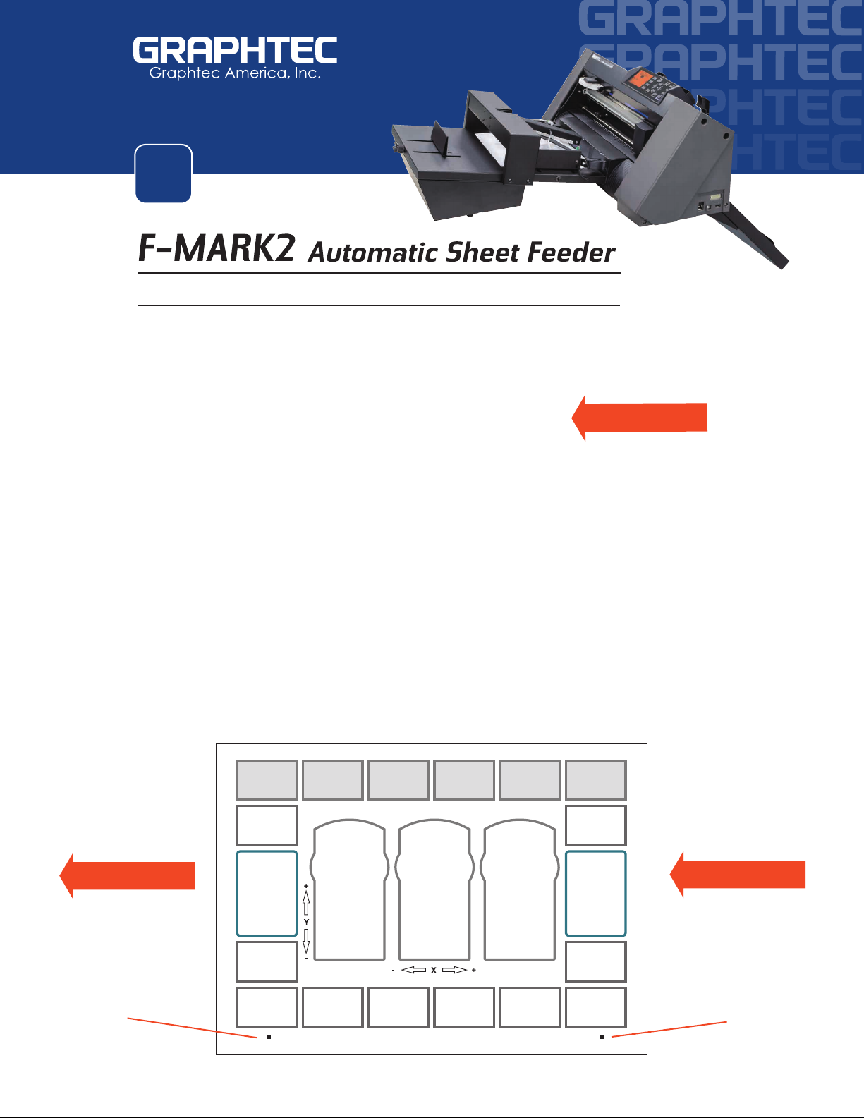
C- Designing Templates for the F-MARK2
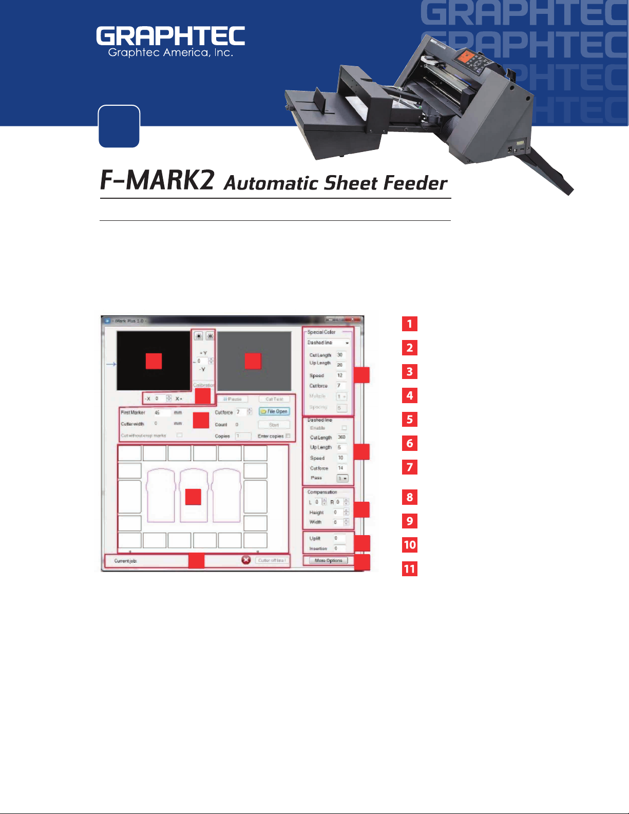
D- iMark Software Overview
A - Calibrating the CCD Camera White Point using Provided Black Media
Chapter 16: How to Calibrate the F-MARK2 ( Starting on page 37)
•Launch the iMark Software
•Manually load the black calibration sheet. While loading the sheet note the
positioning using the iMark software camera viewer window screen.
( you should only see the black sheet - nothing else should be seen)
•Initialize the CE7000 cutter making sure to select Roll 2 on the control panel
( always initialize cutter with Roll 2 )
•Adjust the blade to the thickness of the material being cut
( use loupe from the accessories kit to make ne adjustments )
Refer to Image A
•Load the blade holder on tool position one (the slot furthest back) Refer to Image B
•Set the recommended Force Settings between 9-12, depending on media.
Key Functions & Simplied Operation For Smooth Workow
This quick guide works best when the following has been completed:
• Basic installation of the F-MARK2 unit as outlined in the User’s Manual instructions
•
Installation of the latest version of iMark Plus Software available for downloading at:
www.graphtecamerica.com/software
The User’s Manual for the machine & software will guide you through the complete process.
Please note that the Setup User’s Manual also covers a Troubleshooting Section, so in the
event you run into issues, please refer to the manual before contacting Technical Support.
Graphtec also provides helpful Video Training Videos for the F-MARK2 on our website.
Click on the QR Code below or view the tutorials at www.graphtecamerica.com/videos
SIMPLIFIED BASIC OPERATION WORKFLOW
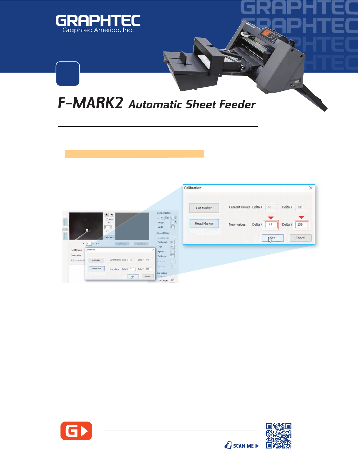
The CE7000 will cut a small square. Peel o the square from the sheet.
You should be left with a square cut showing the white liner.
Go back in the iMark Software and click Read Marker.
Once completed, the Delta X should read a value between 90 -120
while the Delta Y box should read a value between 95 - 135.
Conrm the values by clicking on Set , Then click on the Xto Exit,
The X and Y values you input will be saved to the computer .
( If the values are dierent, repeat calibration. Also, make sure you have sucient lighting )
NOTE: Camera calibration will need to be performed every time changes occur.
When the computer is shut o, when the F-MARK2 is disconnected from
the USB port or if the software stops communicating.
•
•
•
•
•
•
3
In the iMark Plus Software, click on the Calibration Button
( be careful not to have the Dashed Line enabled )
Calibration windows will display two options: Cut Marker or Read Marker
Click on Cut Marker
Calibrating the CCD Camera White Point
CLICK HERE or use QR CODE view STEP by STEP video