CAB WICON User manual

Instructions
WICON
MADE IN GERMANY
Wrap-around applicator

2 2
Type
Wrap-around
applicator WICON
Edition: 06/2022 - Part No. 9003746
Copyright
This documentation as well as translation hereof are property of cab Produkttechnik GmbH & Co. KG.
The replication, conversion, duplication or divulgement of the whole manual or parts of it for other intentions than its original
intended purpose demand the previous written authorization by cab.
Trademark
Windows is a registered trademark of the Microsoft Corporation.
Editor
Regarding questions or comments please contact cab Produkttechnik GmbH & Co. KG.
Topicality
Due to the constant further development of our products discrepancies between documentation and product can occur.
Please check www.cab.de for the latest update.
Terms and conditions
Deliveries and performances are eected under the General conditions of sale of cab.
Further documentation
Operator’s Manual SQUIX
https://www.cab.de/media/pushle.cfm?le=2771
Conguration Manual cab Printers
https://www.cab.de/media/pushle.cfm?le=3257 Programming Manual cab Printers
https://www.cab.de/media/pushle.cfm?le=3047
Instructions
Germany
cab Produkttechnik GmbH & Co KG
Karlsruhe
Phone +49 721 6626 0
www.cab.de
USA
cab Technology, Inc.
Chelmsford, MA
Phone +1 978 250 8321
www.cab.de/us
Taiwan
cab Technology Co., Ltd.
Taipei
Phone +886 (02) 8227 3966
www.cab.de/tw
Singapore
cab Singapore Pte. Ltd.
Singapore
Phone +65 6931 9099
www.cab.de/en
France
cab Technologies S.à.r.l.
Niedermodern
Phone +33 388 722501
www.cab.de/fr
Mexico
cab Technology, Inc.
Juárez
Phone +52 656 682 4301
www.cab.de/es
China
cab (Shanghai) Trading Co., Ltd.
Shanghai
Phone +86 (021) 6236 3161
www.cab.de/cn
South Africa
cab Technology (Pty) Ltd.
Randburg
Phone +27 11 886 3580
www.cab.de/za

3
Table of Contents
1 Introduction............................................................................................................................................4
1.1 Instructions...............................................................................................................................................4
1.2 Intended Use............................................................................................................................................4
1.3 Safety Instructions....................................................................................................................................5
1.4 Safety Marking.........................................................................................................................................5
1.5 Environment.............................................................................................................................................5
1.6 Technical Data..........................................................................................................................................6
1.7 Labels and Transfer Ribbon.....................................................................................................................7
2 Installation..............................................................................................................................................8
2.1 Preparing the Printer................................................................................................................................8
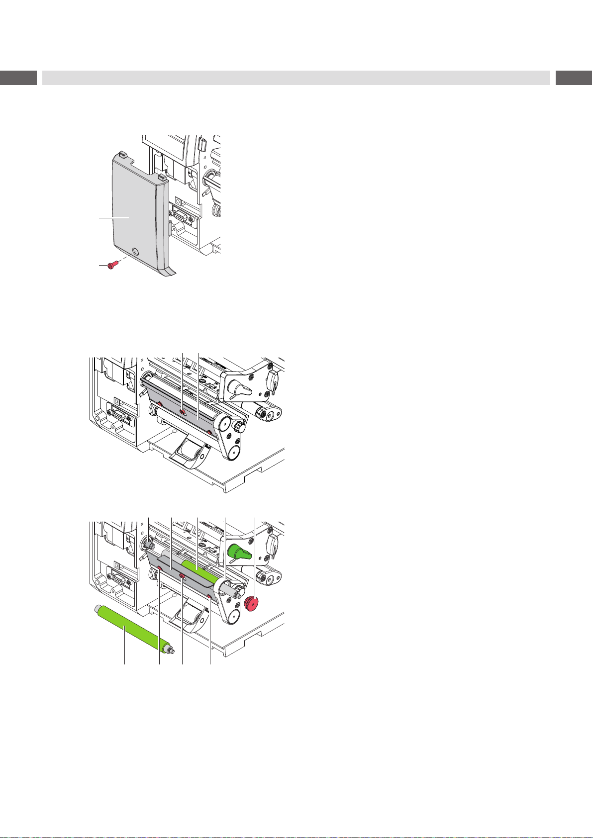
2.1.1 Removing the Front Cover .................................................................................................................8
2.1.2 Replacing Peel-o Plate and Print Roller ...........................................................................................8
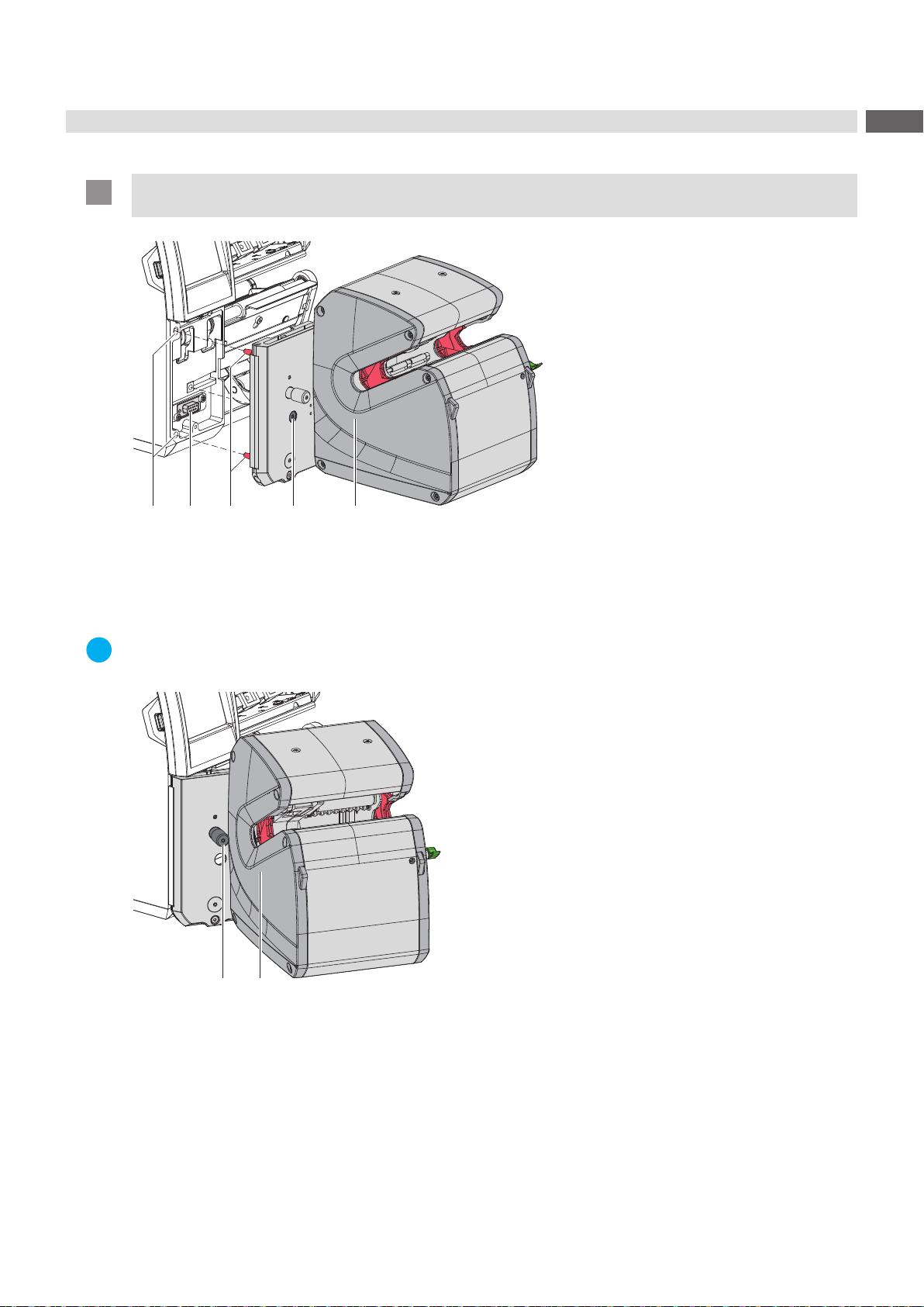
2.2 Mounting the Applicator............................................................................................................................9
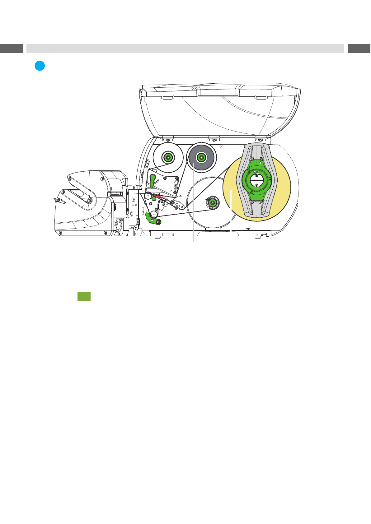
3 Loading Materials.................................................................................................................................10
4 Settings................................................................................................................................................. 11
4.1 Setting the Lateral Position.....................................................................................................................11
4.2 Setting the Stop.......................................................................................................................................11
4.3 Setting the Parallelism of Labels and Products......................................................................................12
5 Operation..............................................................................................................................................13
6 Conguration........................................................................................................................................14
6.1 Settings of the Printer Menu...................................................................................................................14
6.2 Special JScript Commands....................................................................................................................15
7 Fault Correction ...................................................................................................................................16
8 Approvals..............................................................................................................................................17
8.1 Reference to the EU Declaration of Conformity.....................................................................................17
8.2 FCC........................................................................................................................................................17

4 4
1 Introduction
1.1 Instructions
Important information and instructions in this documentation are designated as follows:
Danger!
Draws attention to an exceptionally great, imminent danger to your health or life due to hazardous
voltages.
!
Danger!
Draws attention to a danger with high risk which, if not avoided, may result in death or serious injury.
!
Warning!
Draws attention to a danger with medium risk which, if not avoided, may result in death or serious injury.
!
Caution!
Draws attention to a danger with low risk which, if not avoided, may result in minor or moderate injury.
!
Attention!
Draws attention to potential risks of property damage or loss of quality.
i
Note!
Advices to make work routine easier or on important steps to be carried out.
Environment!
Gives you tips on protecting the environment.
Handling instruction
Reference to section, position, illustration number or document.
Option (accessories, peripheral equipment, special ttings).
Time Information in the display.
1.2 Intended Use
• The device has been designed for operations with SQUIX series printers, being an option for labeling cylindric
items of diameters 2 mm to 16 mm, such as single wires, strands, cables, hoses, tubes or round rods. Any other
use has not been intended. The manufacturer / supplier is not liable for damages resulting from misuse. Risks are
entirely up to operators.
• Intended use also includes observing this manual.
• The device has been manufactured state of the art according to accepted safety regulations. Nevertheless,
operation may pose risks to the life and limb of operators or third parties, or result in limitations to the device and
other material assets.
• The device must be used only in a technically perfect condition, in accordance with its intended use, conscious of
safety and dangers and in compliance with the instructions included in this manual.
!
Attention!
Operatingtheapplicatorrequiresprinterrmware5.41.1,oranylaterrelease.
i
Note!
All the current documentation are provided on the Internet.

5
1 Introduction
1.3 Safety Instructions
• Disconnect from power before installing the applicator or separating it from a printer.
• Operate the applicator only if assembled to a printer.
• Work not described in this manual must be performed only by trained sta or service technicians.
• Improper handling of electronic components and their software may result in malfunctions. Other incorrect work or
modications to the device can limit operational safety as well.
• Always have service work performed by a qualied repair shop, equipped with tools that are necessary to do this
job properly.
• Do not remove warning stickers. Dangers cannot be identied any longer.
!
Warning!
This is a class A product. In a domestic environment this product may cause radio interference in which
case the user may be required to take adequate measures.
1.4 Safety Marking
Figure 1 Safety marking
Risk of crushing by moving parts!
Do not interfere in the applicator’s work area.
1.5 Environment
Obsolete devices contain valuable recyclable materials that should be sent for recycling.
Send to suitable collection points, separately from residual waste.
The modular construction of the device enables it to be easily disassembled into its component parts.
Send the parts for recycling.

6 6
1 Introduction
1.6 Technical Data
Wrap-around applicator WICON
Item Diameter mm 2.0 - 16.0
Length mm at least 132
Centering panel distant to le or right mm 124
Label margin distant to centering panel mm 12.7
Label margin distant to product by stop mm 25 - 100
Deection as for a length of 124 mm mm max. 1
Label Width mm 12.7 - 50.8
Height mm 19.1 - 70.0
Material PVC
Applicator Rates as for printing and applying a label s 1.8 - 6
No. of wrap-arounds 2 - 10
Start as soon as an item has been inserted by hand
via data interface
via I/O interface
Label printer SQUIX 4/MP
Material guidance on the printer centered
Print method Thermal transfer
Print resolution dpi 300 600
Print speed mm/s max. 200150
Print width mm max. 105.7
Material nishing Roll diameter mm max. 205
Core diameter mm 76
Table 1 Technical data

7
1 Introduction
1.7 Labels and Transfer Ribbon
!
Attention!
Only wrap-around labels provided by the manufacturer guarantee proper applications.
Item surfaces must be clean and free of lubricants.
Feed direction
Figure 2 Label dimensions
Part no. Data block
color
Item Ø Label width
B
mm
Printing area
height P
mm
Label height
H
mm
No. of labels
on a roll
R71 resin ribbon
D1
mm
D2
mm Width
mm at least Part no.
5780120.130 white 2.0 4.0 12.7 6.4 19.1 7,450 25 5557401.133
5780121.130 white 2.0 4.0 25.4 6.4 19.1 7,450 40 5557410.133
5780122.130 white 3.0 5.0 25.4 9.5 25.4 5,800 40 5557410.133
5780128.130 white 4.0 8.0 12.7 12.7 38.1 4,000 25 5557401.133
5780129.130 white 4.0 8.0 19.1 12.7 38.1 4,000 40 5557410.133
5780130.130 white 4.0 8.0 25.4 12.7 38.1 4,000 40 5557410.133
5780131.130 white 4.0 8.0 50.8 12.7 38.1 4,000 55 5557402.133
5780133.130 white 6.0 14.0 25.4 19.1 63.5 2,450 40 5557410.133
5780135.130 white 6.0 14.0 38.1 19.1 63.5 2,450 55 5557402.133
5780136.130 white 6.0 16.0 25.4 19.1 70.0 2,250 40 5557410.133
5780137.130 white 6.0 16.0 50.8 19.1 70.0 2,250 55 5557402.133
D1 - Up to this value, the printing area covers the circumference of an item.
D2 - Up to this value, the protective laminate covers the printing area
With labels 19.1 mm to 63.5 m mm high (H), items of diameters 2 mm to 16 mm can be labeled. Using labels 70 mm
high, the smallest possible item diameter is 6 mm.
Table 2 Labels and transfer ribbon

8 8
2 Installation
2.1 Preparing the Printer
2.1.1 Removing the Front Cover
1
2
Loosen screw (2) and remove the front cover (1).
Figure 3 Removing the front cover
2.1.2 ReplacingPeel-oPlateandPrintRoller
21
Loosen screw (1) by a few turns.
Remove the standard peel-o plate (2)
Unlock printhead.
Unscrew the roller bearing (7) from the bearing plate
(6) using a 2.5 mm Allen key.
Pull the standard print roller (8) o the shaft (3) and
through the bearing plate (6).
Clean the shaft (3).
Set a narrow-rubbered print roller (5) onto the shaft
(3) and turn the roller slightly until the hexagon of the
shaft connects with the internal hexagon of the print
roller.
Set the roller bearing (7) onto the roller pin and
screw in the bearing plate (6).
Attach the WICON peel-o plate (4) to screw (1) and
pins (9).
Tighten the screw (1).
8
753 64
9 1 9
Figure 4 Replacing peel-o plate and print roller

9
2 Installation
2.2 Mounting the Applicator
!
Attention!
Disconnect the printer from the power before installing or removing the applicator.
2
1 43 5
Figure 5 Mounting the applicator
Insert the pins (3) of the applicator (5) to the drill holes (1) on the printer.
Push the applicator to the printer to connect the applicator plug with the peripheral port (2) of printer.
Tighten the screw (4) to x the applicator.
i
Note!
The wrapper unit can be pivoted from the printer to insert materials and for service work.
2
1
Figure 6 Pivoting the wrapper unit
Loosen the knurled screw (1).
Pivot the wrapper unit (2) from printer.
When nished, pivot back the wrapper unit and tighten knurled screw.

10 10
3 Loading Materials
i
Note!
For details see the Operator’s Manual of the printer.
1 2
Figure 7 Loading materials
Pivot the wrapper unit from the printer.
Insert ribbon (1) and labels (2) as shown in the gure.
Switch on the printer.
Press to synchronize the paper feed.
Remove blank labels provided on label feed.
Pivot back the wrapper unit and x it to the printer.

11
4 Settings
4.1 Setting the Lateral Position
i
Note!
The lateral alignment of the applicator is necessary to place the labels exactly on the product using the stop
4.2 on page 11.
2
13
5
46
Figure 8 Setting the lateral position
Loosen the screw (2).
Move the wrapper unit (3) by turning the adjusting knob (1) and align the marker (5) to the liner margin (4).
Tighten the screw (2)
4.2 Setting the Stop
Using the stop results in accurate repeatability of label positioning.
i
Note!
Markings on scale (3) are valid only with applicators set in the correct lateral position 4.1 on page 11.
2
13 4 5
Figure 9 Setting the stop
Loosen the screw (1).
Set the scale (3) with the stop (4) so that the desired distance from the label margin to the end of the product is
indicated next to the chassis (2).
Tighten the screw (1).
After loosening the screw (5), align the stop (4) for optimum contact with the product.

12 12
4.3 Setting the Parallelism of Labels and Products
In cases of osets between the layers of a label wrapped around an item, modify the angle of the applicator to the
printer.
2
13
Figure 10 Setting the parallelism
Loosen the knurled screw (2)
Pivot the wrapper unit (3) in small steps by turning the set screw (1).
Tighten the knurled screw (2)
Start labeling and check the result.
Modify the setting if required.
4 Settings

13
5 Operation
5.1 SystemConguration
i
Note!
This chapter describes the needful settings for the WICON functionality.
Further information 6 on page 15 and CongurationManualPrinter.
5.1.1 Backfeed
!
Attention!
After transferring a label from the printer to the applicator it is necessary to feed back the front edge of the
next label to the printing line.
Start menu.
Set Setup > Printing > Backfeed to the setting always.
5.1.2 BasicSettingofthePeel-oPositionwithoutPrintJob
Pivot the applicator from the printer.
Press to recognize the peel position of the labels.
The current label must be peeled-o completely form the liner an the following label should be stopped about
1 mm in front of the peel-o edge.
If necessary adjust the position via Setup > Labelling > Peel-off position.
5.2 Creating a Layout
5.2.1 ActivatingthePeel-oMode
Activate the peel-o mode in the software
This is done with the “P command” in the direct programming, Programming Manual.
5.2.2 JobRelatedCorrectionofthePeel-oPosition
Observe the peel-o position during operation.
Do not change the basic setting 5.1.2 but correct the peel-o position via software.
In the direct programming an oset can be added to the “P” command.
Example: With „P 4.0“ the label will be moved 4 mm further. Programming Manual.
5.2.3 Example
m m
J
H 100,5,T
S l1;.0,.0,63.0,66.0,25.0
P 4.0
G 1.0,1.0,0;R:23.0,18.0,.2,.2[FILL:100%]
T 22,12,180,3,5.5;WICON
T 18,4,180,3,5.5;[SER:0001,1,1]
A 300
Feed direction
B=25
P=19
H=63
For the label format use the complete label height including the
transparent area.
Place all print information in the white area.
Figure 11 Programming example

14 14
5.3 Labelling
52 3
14
Figure 12 Insert product
Set the end of the product (2) to the stop (3).
Grab the product with thumb and index nger of right hand on the outside of the chassis (1). At the same time,
hold the product with your left thumb and index nger 1 to 2 centimeters distant from the chassis.
Keep this grip to guide the product into the centering panels. At this, the thumb and index nger of the right hand
touch the centering panel (5).
Close the centering panels by inserting the product and keep tight exible material. As soon as both panels are
closed, the applicator is ready for labeling.
65
2 6 5
2
þý
Figure 13 Product in centering panel
!
Attention!
When the product (2) is inserted with excessive power it can be moved beyond the axle (6) of the appli-
cator. Following the labels can form loops on the product.
Depending on the setting, wrapping is triggered immediately or by a START signal. At this, the touch guard (4) is
closed and the label wrapped around the product.
Hold the product with both hands during wrapping.
After wrapping has nished, the touch guard is opened.
Remove the labeled product.
5 Operation

15
6 Conguration
i
Note!
The values of the setup are basic settings for the current printer/applicator combination.
After changing the applicator or printer a re-adjustment may be necessary.
Changesrequiredforprocessingdierentprintjobsshouldbeimplementedbyadditionalosetsavailableinthe
software.
Theosetvaluesfromsetupandsoftwareareaddedtogetherforexecution.
FordetailedinstructionsforcongurationCongurationManualoftheprinter.
6.1 Settings of the Printer Menu
i
Note!
InthatchapteraredescribedthespecicapplicatorparametersofthemenuLabelling only.
FormoreinformationaboutthecongurationCongurationManualoftheprinter.
Start menu.
Select Setup > Labelling.
Parameter Description Default
Device info Applicator information:
Software edition, diameter of the last product,
number of label applications, error notes, number of rotations
Calibrate device Calibration of the diameter measurement by means of a product with a diameter of 10 mm
With service key inserted the diameter of the calibrating product can be set.
Reset service
counter Access only with service key inserted!
Reset of the applicator’s service counter
Cycle sequence Select type of operation:
Print-apply:
Printing a label and applying it to an item are triggered by a START signal.
After a cycle has nished, the transport module contains no label.
Apply-print:
Printing an initial label is triggered by a separate signal, so is its transfer to
the transport module.
A START signal triggers the label be applied and, in subsequence, the
printing of another one.
After a cycle has nished, the transport module contains a label.
Print-apply
Automatic FSTLBL ¾only with Cycle sequence = Apply-print
The FSTLBL signal is triggered automatically in subsequence to a print job
been started.
Off
Peel-off position Shifting the peel-o position with reference
to the rear margin of a label
Modication is possible also via software.
Conguration values add up with those of software.
0.0 mm
Wrap start Labeling is triggered automatically by inserting a product or by an external
signal Automatic
Check for product Access only with service key inserted!
Checking of the centering panel state Enabled
Table 3 Menu Labelling

16 16
6 Conguration
Calibrate Device
Switch on the device.
Start menu.
Select Setup > Labelling > Calibrate device.
Insert a 10-mm test pipe (Part No. 5988543).
Select Continue.
The wrapping unit will be turned ten times with closing and opening the jaws and measuring the diameter of the
test pipe.
The display shows the success of the calibration, the determined oset and the tolerances of the oset value.
Select Continue.
The determined oset will automatically be stored and considered for future measurements.
6.2 SpecialJScriptCommands
i
Note!
Some parameters of the menu Setup > Labelling canbechangedoroverriddenbyJScriptcommandsinaprint
job.
These changes are valid for the current print job only.
!
Attention!
The meaning of the commands O Ax=y in the following table are valid for WICON only.
Forotherapplicatorsthemeaningofthesecommandsaredierent.
Command O Ax=y
xMeaning Value range y Default Example
1 Wrap start START signal
Automatic Automatic O A1=START signal
Table 4 O Ax commands
!
Attention!
The y-values must be set as shown in the table regarding blanks and case sensitivity.

17
7 Fault Correction
Error
message Cause Remedy
Label on belt
detected A label on the transport belt is detected
when a new labeling cycle shall be started
after an error has occurred or the previous
job has been canceled.
Remove labels from transport belt.
Touch guard error Failure of the touch guard movement Remove labels and product from the applicator.
If error recurs call service.
No label on belt
detected After a labeling cycle is started no label is
detected on the transport belt. Remove labels and product from the applicator.
If error recurs call service.
No product
detected The diameter recognized by the applicator
is under the dened minimum diameter
Use products with correct diameters.
Wrapping failed Failure of the wrapping unit movement Remove labels and product from the applicator.
If error recurs call service.
Table 5 Fault correction
How to remove labels from the applicator
3
142
Pivot the applicator (1) from the printer.
Unlock and open the door (4).
Remove the labels from the inside of the appli-
cator.
Press the button (2) to promote the transport
system (3) moving backwards.
Close the door and pivot back the applicator.
Figure 14 Removing labels from the applicator

18 18
8 Approvals
8.1 Reference to the EU Declaration of Conformity
The WICON applicators comply with the relevant fundamental regulations of the EU Rules for Safety and Health:
• Directive 2014/30/EU relating to electromagnetic compatibility
• Directive 2011/65/EU on the restriction of the use of certain hazardous substances in electrical and electronic
equipment
• Delegated directive (EU) 2015/863 as regards the list of restricted substances
EU Declaration of Conformity
https://www.cab.de/media/pushle.cfm?le=3982
8.2 FCC
NOTE : This equipment has been tested and found to comply with the limits for a Class A digital device,
pursuant to Part 15 of the FCC Rules. These limits are designed to provide reasonable protection against
harmful interference when the equipment is operated in a commercial environment. The equipment
generates, uses, and can radiate radio frequency and, if not installed and used in accordance with the
instruction manual, may cause harmful interference to radio communications. Operation of this equipment in
a residential area is likely to cause harmful interference in which case the user may be required to correct the
interference at his own expense.
Table of contents
Popular Packaging Equipment manuals by other brands

Titan
Titan TA750 instruction manual

Polychem
Polychem PWT Operation manual and spare parts list

Dispens-a-Matic
Dispens-a-Matic Bottle-Matic II Information and instructions

M.J. MALLIS GROUP
M.J. MALLIS GROUP SIAT K11R Instructions and Spare Parts List

Snell
Snell ES-103 Operating manual and Spare parts list

Extend
Extend EXS-303 Operation manual