Fromm TP-601D1 Guide


Explanations for Each Model NO. :
TP-601D1 : Standard Single Phase Model
TP-601D3 : Standard Three Phase Model
TP-601L1 : Low Table Single Phase Model
TP-601L3 : Low Table Three Phase Model
01/10/08

PART I
CONTENTS
1. Safety Instructions …………………………………
…
1~2
2. Construction and Function of Units ……………….. 3~4
3. Technical Data ……………………………………… 5~6
4. Control Panel ………………………………………
…
7
5. Electric Control Unit ………………………………
…
8
6. How to Load P.P. Strap ……………………………
…
9~10
7. How to Operate ……………………………………… 11
8. Recommend for Trouble-free Operation ……………
…
11
9. Adjustments ………………………………………… 12~17
10. Installation of Arch Unit ……………………………
…
18~19
11. Wiring Diagram ……………………………………
…
20~25
12. Troubleshooting ……………………………………
…
26
01/10/08

(1) Before operating
a. Please always wear proper eye protection and safety gloves before operating this
Eye protection must be worn Safety gloves must be worn
b. Please make sure if the power voltage is correct.
c. It can only be operated with P.P. strap; not PET strap or Polyester cord strap.
(2) During operating
a. The weight of package should not exceed 100kg, and the size should not be
less than 130mm (width) x 20mm (high).
b. Check if the machine emits any smokes or unusual sound when it is running.
(3) After operating
a. Please pull out the power plug.
b. Please get rid of the dirt or impurity on the machine.
(4) Signs
Caution, risk of electric shock Do not touch!
Heiss!Hot! chaud!
c. Warning
c-1 For your own safety, please read instruction manual before operating. Keep
away from arch while the machine is running.
c-2 Do not put your hands or body into the Archworking area when the machine is
machine.
running.
-1-
1. Safety Instructions
01/10/08

a. Please turn off the power before opening the top plate.
b. Please do not touch the heater due to the high temperature.
c. Be careful with the heater if you open the upper top plate.
(6) Maintenance
(7) Other remainders
a. Do not alter or bypass protective interlocks
b. The operation manual must remain attached to the machine at all times
c. Do not alter circuits and machine unless authorized to do so by the manufacturer.
d. All electrical apparatus must be properly grounded.
e. Wire the machine according to the local electrical code.
-2-
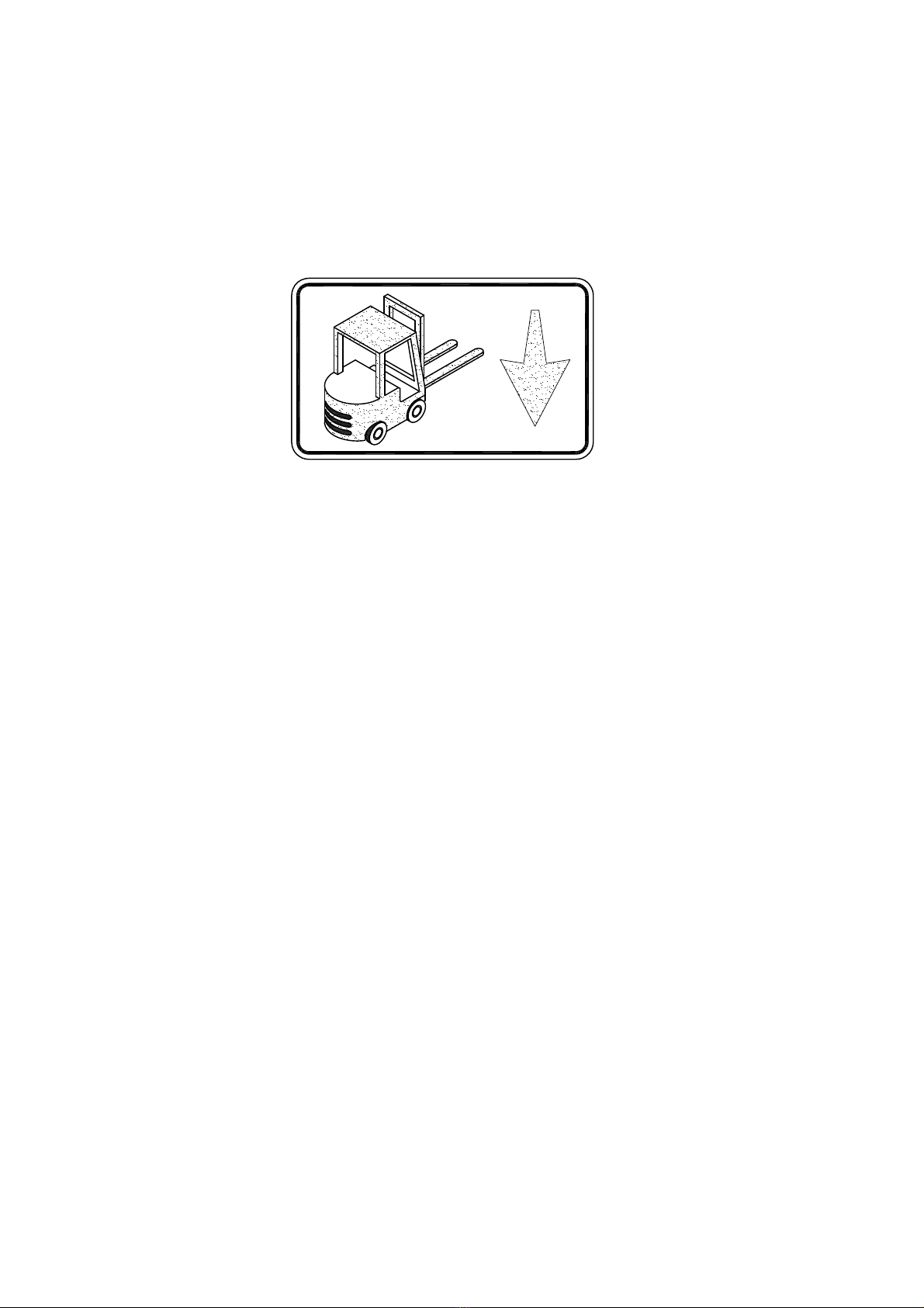
When the machine arrives in your warehouse, you need to use a forklift to
take it off from the pallet. If you could go down to the bottom side of
the machine, you would see an indication sticker as follows: (TP-601L)
position. After making few distance adjusting, you then could drive the
Follow this sticker and lead the teeth of a forklift to that indicated
teeth in and take off the machine.
(5) Attention
01/10/08

1 Strapping head unit
2 Bandway unit
5 Body frame unit
6 Electric control unit
8 Auto strap feeding unit 3 Accumulator unit
This unit is the most important part of the
machine for cutting and sealing of P.P.
strap.
This is the arch track through which
P.P. strap forwards or reverses.
This unit accumulates the quantity of strap required
for smooth feeding into the chute track.
Holds the strap coil.
(If strap core is
280mm, you can take
off the center drum to
4 Reel unit
have core size 200mm.)
-3-
2. Construction and Function of Units
a. (TP-601D)
01/10/08

-4-
b. (TP-601L)
through which P.P. strap
2 Bandway unit
This is the arch track
forwards or reverses.
arch track.
3 Pool unit
This unit pools strap
adeqately for its
smooth feeding in
4 Reel unit
(If strap core is 280mm,
you can take off the center
drum to have core size 200mm.)
Holds the strap coil.
machine for cutting and sealing of P.P.
This unit is the most important part of the
1 Strapping head unit
strap.
5 Body frame unit
6 Electric control unit
8 Auto strap feeding unit
01/10/08

-5-
3. Technical Data
a. TP-601D
Sealing method Heat
Strap width:
Strap thickness:
Strap reel diameter:
Width :
Depth:
Table height:
Electrical connection:
8 mm to 12 mm (3/8" - 1/2")
0.55 mm up to 0.75 mm (0.022" - 0.03")
200 mm (8" nominal)
1430 mm (56.3")
620 mm (24.4")
810 mm (31.9")
AC 110V/220V/230V/240V (50/60Hz), 1PH
AC 220V/380V/400V (50/60Hz), 3PH
220 kg (341.7 lbs.)Weight: 83 dB (A)Noise emission: 5°C ~ 40°C (41°F ~ 104°F)Ambient temp:
01/10/08

-6-
b. TP-601L
Sealing method Heat
Strap width:
Strap thickness:
Strap reel diameter:
Width :
Depth:
Table height:
Electrical connection:
8 mm to 12 mm (3/8" - 1/2")
0.55 mm up to 0.75 mm (0.022" - 0.03")
200 mm (8" nominal)
1880 mm (74")
620 mm (24.4")
410 mm (16.1")
AC 110V/220V/230V/240V (50/60Hz), 1PH
AC 220V/380V/400V (50/60Hz), 3PH
235 kg (518.1 lbs.)Weight:
Noise emission:
Ambient temp: 83 dB (A)
5°C ~ 40°C (41°F ~ 104°F)
01/10/08

RESET
TP-601D
1 Start Switch
2 Reset switch
3 selector switch
4 Tension Adjustment Knob
-7-
4. Control Panel
This is the switch to start a strapping operation.
A strapping cycle is completed only after actuation of
this switch.
This is the switch to activate auto strap feeding.
In addition, it is used for troubleshooting. If the strap is
mis-fed, you can push this button to solve the problem.
While selector switch is placed to the position , the
machine will automatically strap the package when it
isplaced on the table and passes the chute arch, if the
package remains under the arch, the strapping cycle
will continue. While the selector switch is placed to the
position , after positioning the package under the
arch, push the "START" switch, then one strap will be
applied.
External adjustment of strap tension by step-by-step
rotation of this knob.
RESET
TP-601L
01/10/08

TP-601D3
2A
Fuse
H.T
FAN
TP-601D1
2 Sec
30
T1(R)
0
M5-1
BRK.
M5
Fuse
2A
2 Sec
P.C.B.
1A
Fuse
1
30
T1(R)
0
L3
Fuse
7A
H.T
220V
110V 3A
2A
Fuse
FAN M5-1
BRK.
M5
2A
2A
Fuse
P.C.B.
1A
1A
Fuse
1
M3
10A
Fuse
5A
7A
Fuse
L2
7A
Fuse
L1
10A
7A
Fuse
M2
10A
5A
Fuse
M1
240V
230V
-8-
5. Electric Control Unit
(TP-601D1, TP-601D3, TP-601L1, TP-601L3)
Timer, T1 30 : T1 timer determines the time necessary for strap take-up. Set T1
timer bearing in mind the time required for strapping the minimum-size package.
Normally, Timer T1 is set at about 0.5 seconds, but may have to be adjusted depending
on a package size.
TP-601L1
TP-601L3
01/10/08

Step 1
Step 2
Step 3
Step 4
-9-
6. How to Load P.P. Strap
a. TP-601D
Ensure that the power
switch is turned off before
loading P.P. strap.
‧
Place a strap coil on the reel drum in
according to the arrow direction as
indicated on the Reel Out Circular 9
.After placing it, put the Reel Out
Circular on the strap coil and tighten it
by the Reel Nut Handle 10 .
Thread the tip of P.P. strap into the Band
Guide Roller 11 . After that, push it
through the Free Angle 12 . At this
moment, twist the strap so that the inside
part of the P.P. strap turns out downward
and outside surface touches on the roller.
See the drawing.
Insert P.P. strap into the Pool Feed
Shooter 13 , pushing the lever 14
down and feed P.P. strap about 1-2 cm
beyond Pool rollor 15 .
Turn on the power supply switch, and
then push Reset Switch 17 . After
about 4 seconds, the strap will
automatically go into the arch and pool.
01/10/08

Step 1
Step 2
Step 4
-10-
b. TP-601L
Ensure that the power
switch is turned off before
loading P.P. strap.
‧
Place a strap coil on the reel drum in
according to the arrow direction as
indicated on the Reel Out Circular 9
.After placing it, put the Reel Out
Circular on the strap coil and tighten it
by the Reel Nut Handle 10 .
Thread the tip of P.P. strap into the Roller
Bracket Ass'y 12 . After that, thread it
through the Band Guide Roller 11 .
Turn on the power supply switch, and
then push Reset Switch 17 . After
about 4 seconds, the strap will
automatically go into the arch and pool.
Insert P.P. strap into Pool Feed Shooter 13
and turn Accumulator Main Roller 14 until
the P.P. strap about 1-2 cm beyond the Main
Roller 14 .
Step 3
01/10/08

lock at the same time and the strap will
(1) Turn on the switch (make a 90-degree
clockwise turn). The front door will
be automatically fed into the
7. How to Operate 8. Recommend for Trouble-free
Operation
accumulator box. If you want to open
the front door, turn off the switch first
(make a 90-degree counterclockwise
turn).
door without risk. (See drawing below)
The operator can now open the front
(2) Wait for about 3 minutes until
the heater element has reached its
required operating temperature.
(3) Place a package on the center
of the strapping head. Push the start
switch 1 (P7), and the package
is automatically strapped. The
strapping operation is repeated if the
start switch is pushed again.
(4) After operation, turn off the
power supply switch.
(1) Make sure to turn off the power supply
switch, when maintenance and/or exchange
of strap coil is required.
(2) Pull the strap out of the Accumulator Box
and rewind it on the Reel Unit to prevent
cambering, if the machine will not
be used for long periods of time.
(3) In order to change the strap width, use
the strap conversion kit which is sold
as an option.
(4) When the electric plug receptacle has
to be changed, check the revolving
direction of motor.(P9 NO. 15 )(Only 3PH).
(5) Always keep the machine clean,
especially by removing dust and strap
fluff in the vicinity of the sealing head
and heater unit.
(6) Do not use extension cords.
-11-
01/10/08

TEMP−CONT
Output:3−5.2V
Input:110V, 220V / 230V / 240V
-12-
9. Adjustments
(1) Heater temperature
Set the knob to position 3 or 4
Adjust the heater temperature by selecting
a value between 1 and 6. Choose the suitable
conditions of the machine. If the heater
temperature, bearing in mind the environmental
or reduce the heater-knob value until
seal will not be obtained. Gradually increase
temperature is too high or too low, a proper
obtainging an optimum seal.
01/10/08

(2) Feed and take-up
mechanism
and the Upper Shaft Spring Hook 24 should
be the thickness of the strap you are using.
Strap can only be taken up properly if
Normally, this unit is set to accept P.P. strap
and take-up will become irregular.
If this unit is not correctly adjusted, strap feed
If a different strap thickness is used, adjust the
with the thicknesses of 0.55mm-0.75mm
section marked by a circle in the drawing so that
the clearance between the Upper Roller Spring 23
this unit is precisely adjusted. (If not, strap
there is no clearance.
the chute arch track when feedinig into it if
the package ) Moreover, strap will leave
will be sealed before being tightened around
original position. Insert the strap
a. Check if the control unit returns to its
between Feed Roller 22 and Upper Feed
Roller 21 .
Block Arm 25 with the Press Arm Shaft
26 . Press Arm Shaft can then easily be
b. Loosen 2 Bolts 27 holding the rihgt-hand
moved by hand.
Upper Shaft Spring Hook 24 the same
the Upper Roller Spring 23 and the
c. Adjust so that there is a clearance between
as the thickness of the strape you
are using.
d. Tighten 2 Bolts 27 .
-13-
01/10/08

stops at the correct position.
Followe 41 stops at the correct position.
c. If the problem has not been eliminated, please repeat the "Step One" until the Cam
b. Reset the machine and allow it to cycle again to ensure that the Cam Follower 41
M6 screws.
a. Loosen the two M6 screws and turn the Cam Roller slightly clockwise, then tighten the
If Cam Follower 41 stops the correct position:
before
Adjustment
the following instructions.
position on the Tension Cam 42 as shown in If not, please adjust according to
Cam 32 is activated. At this time, the Cam Follower 41 must stop at the corner
The machine will stop as soon as the LS3 Proximity Sensor 31 detects that Limit Switch
figure 1-1.
Cam 32 while the machine is in home position.
shows the correct position for LS3 Proximity Sensor 31 and the Limit Switch
Figure 1
(3) How to adjust LS3, LS2
-14-
01/10/08

until the Cam Follower 41 stops at the correct position.
a. Please also loosen the M6 screws but turn the Cam Roller slightly counterclockwise
If Cam Follower 41 stops beyond the correct position:
Limit Switch Cam 34 while machine is running.
Figure 2
shows the correct position for LS2 Proximity Sensor 33 against the lobes of the
Cam 34 , the machine will stop about 0.3 seconds so that the machine can switch to
Cam 42 as shown in figure 2-1. If the Cam Follower is not at the correct position, please
take-up . In the meantime, Cam Follower 41 has to stay on the corner position of the Tension
When LS2 Proximity Sensor 33 detects Lobe A of the activated running Limit Switch
make the same adjustment as for LS3.
-15-
01/10/08

a. (TP-601D)
The machine has already been set in its
adjustment is necessary, proceed as shown
in the following drawing.
Accumulator Box.
required, depending on the actual
quality or thickness of the strap used. If
27 and turn the Screw Bolt 28 counterclockwise.
in the Accumulator Box, loosen the Nut
a-1 In case that there is an insufficient amount of strap
strap in the Accumulator Box, loosen the Nut
a-2 In case that there is an excessive amount of
27 and turn the Screw Bolt 28 clockwise.
However, some adjustment may be
-16-
(4) Amount of strap in Accumulator Box
01/10/08

-17-
Micro Switch(LS4)
M6 Screw
T7-3-10190
Fig A
If you have moved the LS4 Micro Switch to the left up to the bottom but you still
do not have enough P.P. strap in the accumulator box, you can loosen nut E and
turn the bolt D ccw increase the amount of P.P.strap in the accumulator box. finally
D
E
b-1 Fig A :
T7-3-10200
(4) Amount of strap in Accumulator Box
b. (TP-601L)
tighten the nut E.
Less
More
01/10/08
This manual suits for next models
3
Table of contents
Other Fromm Packaging Equipment manuals
Popular Packaging Equipment manuals by other brands

Pregis
Pregis Quantum Pro 4068969 user manual

Atlanta Attachment Company
Atlanta Attachment Company 1390BX Technical Manual & Parts Lists

Matco
Matco T7 PRO CC Basic Manual

lnauen Maschinen
lnauen Maschinen VC999 04i operating instructions

3M
3M AccuGlide HST 39100 Instructions and parts list

Status
Status PROVAC 360 user manual