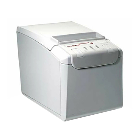
GRAPHTEC DP-581H Parts list manual


2
Introduction
Thank you for purchasing the DP-581H thermal printer. This document explains the printer
functions of the midi LOGGER series. For details on the standard functions of the midi LOGGER,
see the instruction manual of each product. Please read this document carefully, and use the
product properly.
Notes on the Use of This Manual
1. All rights reserved. No part of this publication may be reproduced, stored in a retrieval
system, or transmitted, in any form or by any means, without the prior written permission of
Graphtec Corporation.
2. The specifications and other information in this manual are subject to change without notice.
3. While every effort has been made to supply complete and accurate information about this
product, please address any inquiries about unclear information, possible errors, or other
comments to your sales representative or nearest Graphtec vendor.
4. Notwithstanding the preceding paragraph, Graphtec Corporation assumes no liability for
damages resulting from the use of the information contained herein or of the product.
About Registered Trademarks
Microsoft and Windows are registered trademarks or trademarks of Microsoft Corporation in the
U.S. and elsewhere.
Other company names and product names included in this manual are registered trademarks or
trademarks of their respective companies.
Copyright
All copyrights regarding this manual belong to Graphtec Corporation.

3
Contents
CAPTER 1 General Description............................................................................................................... 6
1.1 Overview......................................................................................................................................... 6
1.2 Features.......................................................................................................................................... 6
Portability........................................................................................................................................ 6
Wireless LAN Connection .............................................................................................................. 6
A variety of print features ............................................................................................................... 6
1.3 Operating Environment................................................................................................................... 7
CAPTER 2 Preparation............................................................................................................................ 8
USB connection................................................................................................................................. 8
Required items ............................................................................................................................... 8
Connection procedure .................................................................................................................... 8
Wireless LAN connection................................................................................................................... 9
Required items ............................................................................................................................... 9
Connection procedure .................................................................................................................... 9
Wired LAN connection..................................................................................................................... 11
Required items ............................................................................................................................. 11
Connection procedure .................................................................................................................. 11
CAPTER 3 Print Functions..................................................................................................................... 13
3.1 Direct Y-T Printing ........................................................................................................................ 13
3.2 Hard Copy Printing ....................................................................................................................... 14
3.3 Memory Out Printing..................................................................................................................... 15
3.4 List Printing................................................................................................................................... 16
3.5 Logging Printing............................................................................................................................ 17
During direct logging........................................................................................................................ 17
During memory out logging.............................................................................................................. 18
CAPTER 4 Configuration ....................................................................................................................... 19
4.1 OTHER menu ............................................................................................................................... 19
Printer function................................................................................................................................. 20
Usage interface ............................................................................................................................ 20
Printer name................................................................................................................................. 20
Printer search............................................................................................................................... 21
Print test ....................................................................................................................................... 21

4
Information....................................................................................................................................... 22
Printer information........................................................................................................................ 22
4.2 Printer Menu (Y-T)........................................................................................................................ 23
Printer.............................................................................................................................................. 23
Trigger Sync .................................................................................................................................... 24
Print timing ................................................................................................................................... 24
Chart speed..................................................................................................................................... 27
External feeding ........................................................................................................................... 28
Division function ........................................................................................................................... 28
Fit to the screen Time/DIV............................................................................................................ 28
Grid type.......................................................................................................................................... 29
Envelope mode................................................................................................................................ 30
Turning the envelope mode on and off......................................................................................... 30
Forced envelope mode................................................................................................................. 30
Information channel settings............................................................................................................ 31
Annotation settings.......................................................................................................................... 32
Print interval ................................................................................................................................. 32
Flying annotation .......................................................................................................................... 32
Title print....................................................................................................................................... 34
Channel print................................................................................................................................ 34
Marker/mark settings ....................................................................................................................... 35
Timing marker .............................................................................................................................. 35
Distance marker ........................................................................................................................... 35
Channel marks ............................................................................................................................. 36
Alarm printing ............................................................................................................................... 36
Scale printing................................................................................................................................... 37
List printing ...................................................................................................................................... 38
4.3 Printer Menu (XY)......................................................................................................................... 39
Printer settings ............................................................................................................................. 39
XY output format .......................................................................................................................... 39
Grid type....................................................................................................................................... 39
Scale printing................................................................................................................................ 39
List printing................................................................................................................................... 40
4.4 File Menu...................................................................................................................................... 41
Screen printout............................................................................................................................. 41
4.5 Function Key (GL980/GL2000 only) ............................................................................................. 42
Screen printout............................................................................................................................. 42
4.6 Menu during Data Playback.......................................................................................................... 43
Y-T................................................................................................................................................... 43

5
All data Y-T printout...................................................................................................................... 44
Cursor Y-T printout....................................................................................................................... 44
Cursor logging printout................................................................................................................. 44
Printer settings ............................................................................................................................. 44
XY print............................................................................................................................................ 45
Screen printout............................................................................................................................. 45
CAPTER 5 Specifications ...................................................................................................................... 46
5.1 Connection Specification .............................................................................................................. 46
5.2 Print Functions.............................................................................................................................. 46

6
CAPTER 1 General Description
This chapter provides an overview.
1.1 Overview
When you connect a DP-581H thermal printer to the midi LOGGER series, the logger signals can
be printed on the printer. The waveforms of the input signals can be printed in real time,
numeric values can be printed as a log, and the displayed screen can be printed.
1.2 Features
Portability
By combining the DP-581H thermal printer and the compact midi LOGGER series, you can
create a mobile print environment.
Wireless LAN Connection
The GL840/GL240 midi LOGGER can be connected to a printer through wireless LAN using the
optional wireless LAN unit (B-568).
A variety of print features
Direct Y-T printing can be used to print input signals in real time. Further, the print timing can
be synchronized to triggers.
Data recorded in the past can be played back and printed. The period in which you want to print
can be specified with cursors.
The logging print function allows printing of numeric values such as those in CSV data.

7
1.3 Operating Environment
The following table shows the midi LOGGER series instruments that can connect to the printer.
If you are already using a midi LOGGER series instrument, you need to update the firmware.
You can download the firmware from the Graphtec website.
Download page
http://www.graphteccorp.com/support/software/instruments.html
Compatible
model
Compatible firmware version
Connection method
GL980
Ver.1.30 or later
USB connection, Wired LAN connection
GL2000
Ver.1.30 or later
USB connection, Wired LAN connection
GL840-M/WV
Ver.1.50 or later
Wireless LAN connection, Wired LAN
connection
GL240
Ver.1.50 or later
Wireless LAN connection
※Do not use a USB hub or the like when making a USB connection.
※To use wired LAN, you need a separate off-the-shelf wireless LAN access point.
※Only a single logger can be connected to a printer.

8
CAPTER 2 Preparation
This chapter explains the procedure to connect a printer to the midi LOGGER series. For the
preparation of the printer itself, see the instruction manual or setup guide for the printer. The
method of connecting a midi LOGGER series and printer varies depending on the interface that
you will use.
USB connection
Connect the printer to the logger using a USB cable. This connection is possible on the
GL980/GL2000.
Required items
●DP-581H printer
●GL980 or GL2000 midi LOGGER
●USB cable (Type-A to Type-C) for connecting the printer to the GL980/GL2000
Connection procedure
1. Printer configuration
1-1. Turn the printer on.
2. Logger configuration
2-1. Turn the logger on.
3. USB connection
3-1. Connect the Type-A end of the included USB cable to the GL980/GL2000 USB host port
and the Type-C end to the printer.
4. Printer registration
4-1. Press the MENU key on the logger to open the OTHER menu.
4-2. Under the printer function, set the interface to use to USB.
5. Test print
5-1. Perform a test print, and check that it is printed properly.
※Do not use a USB hub or the like when making a USB connection.

9
Wireless LAN connection
To use wireless LAN connection, a B-568 wireless LAN unit must be connected to the GL840 or
GL240.
Required items
●DP-581H printer
●GL840 or GL240 midi LOGGER
●B-568 wireless LAN option
●Remote Network Driver Interface Specification (RNDIS) driver
* A PC driver for making a Web connection to the printer
●USB cable (Type-A to Type-C) for connecting the printer to the PC
●Windows PC (Windows 7, Windows 8/8.1, Windows 10)
Connection procedure
1. Logger configuration
1-1. Connect the B-568 wireless LAN unit.
For the connection procedure, see the B-568 instruction manual.
1-2. Turn the power on.
1-3. Set the wireless LAN setting to access point.
For the procedure to change to the access point mode, see the instruction manual of the
logger.
2. Printer configuration
2-1. Install the RNDIS driver in the PC.
For the installation procedure, see the printer instruction manual.
2-2. Turn the printer on.
2-3. Connect the printer to the PC using a USB cable.
Connect the Type-A end of the included USB cable to the PC and the Type-C end to the
printer.
2-4. Make a Web connection to the printer, and configure the wireless LAN function of the
printer.
For the procedure to make a Web connection to the printer and that to change the
printer settings through the Web connection, see the printer instruction manual. For the
SSID and key, set the same SSID and key as the logger access point set in step 1-3.

10
3. Printer registration
3-1. Press the MENU key on the logger to open the OTHER menu.
3-2. Under the printer registration, set the interface to use to wireless LAN.
The logger needs to be set to access point mode in advance in step 1-3.
3-3. The printer name will be displayed when you perform a printer search. Press ENTER to
select the printer and complete the registration.
※Check
If the printer name does not appear, check the SSID, encryption method, encryption key, and so
on set in “2. Printer configuration.” Moreover, check the IP address and network mask to verify
that the printer is in the same segment as the logger’s wireless LAN.
4. Test print
4-1. Perform a test print, and check that it is printed properly.
※Check
If the test print fails, check the following.
- Check that the wireless connection between the logger and printer is established. You can
check whether a wireless connection is established with the WIFI setting of the printer.
- Check the printer’s IP address and network mask to verify that the printer is in the same
segment as the logger’s wireless LAN.
- Turn the logger and printer off and then back on.
※If the communication speed decreases due to the communication environment, print data
may be lost.
※When the printer is connected with the logger’s wireless LAN setting set to access point
mode, the WL sensor (GL100-WL) cannot be connected.
※If you want to connect the logger as a client to an off-the-shelf wireless LAN router, set the
wireless LAN setting to station, and set the same SSID and key as the off-the-shelf wireless
LAN router. Then, refer to the procedure for the wired LAN connection.
※Only a single logger can be connected to a printer.

11
Wired LAN connection
To use a wired LAN connection, you need an off-the-shelf wireless LAN router. Obtain it in
advance. Make sure that the off-the-shelf wireless LAN router meets the following
specifications.
IEEE802.11n compatible
Has a wired LAN port
Has a router mode (RT mode)
※Graphtec will not guarantee the operation of the off-the-shelf wireless LAN router or answer
any questions about it.
Required items
DP-581H printer
GL840 or GL980/GL2000 midi LOGGER
Off-the-shelf wireless LAN router
Remote Network Driver Interface Specification (RNDIS) driver
* A PC driver for making a Web connection to the printer
USB cable (Type-A to Type-C) for connecting the printer to the PC
LAN cable for connecting the logger to the wireless LAN router
Windows PC (Windows 7, Windows 8/8.1, Windows 10)
Connection procedure
1. Off-the-shelf wireless LAN router configuration
1-1. Set the router to router mode.
For the procedure to change the mode, see the instruction manual for the wireless LAN
router.
2. Logger configuration
2-1. Connect the off-the-shelf wireless LAN host to the logger using a LAN cable.
2-2. Turn the logger on.
2-3. Press the MENU key on the logger to open the I/F menu.
2-4. Set the network addresses according to the off-the-shelf wireless LAN router settings.
Normally, an off-the-shelf wireless LAN router has an auto network address assignment
function (DHCP), so you can set the “Auto IP address assignment” of the logger to
“Enabled” to automatically obtain the addresses. If the DHCP on the wireless LAN router
is disabled, set the “Auto IP address assignment” of the logger to “Disabled” and set the
addresses.

12
3. Printer configuration
3-1. Install an RNDIS driver in the PC.
For the installation procedure, see the printer instruction manual.
3-2. Turn the printer on.
3-3. Connect the printer to the PC using a USB cable.
Connect the Type-A end of the included USB cable to the PC and the Type-C end to the
printer.
3-4. Make a Web connection to the printer, and configure the wireless LAN function of the
printer.
For the procedure to make a Web connection to the printer and that to change the
printer settings through the Web connection, see the printer instruction manual. Set the
same SSID and key as those of the wireless LAN router.
4. Printer registration
4-1. Press the MENU key on the logger to open the OTHER menu.
4-2. Under the printer registration, set the interface to use to LAN.
4-3. The printer name will be displayed when you perform a printer search. Press ENTER to
select the printer and complete the registration.
If the printer cannot be found, check that the settings are correct according to the
configuration procedure.
※Check
If the printer name does not appear, check the SSID, encryption method, encryption key, and so
on set in “2. Printer configuration.” Moreover, check the IP address and network mask to verify
that the printer is in the same segment as the logger’s wireless LAN.
5. Test print
5-1. Perform a test print, and check that it is printed properly.
※Check
If the test print fails, check the following.
- Check that the wireless connection between the logger and printer is established.
You can check whether a wireless connection is established with the WIFI setting of the printer.
- Check the printer’s IP address and network mask to verify that the printer is in the same
segment as the logger’s wireless LAN.
- Turn the logger and printer off and then back on.
※Only a single logger can be connected to a printer.
※If the communication speed decreases due to the communication environment, print data
may be lost.

13
CAPTER 3 Print Functions
The following main print functions are available.
Direct Y-T printing
Hard copy printing
Memory out printing
List printing
Logging printing
3.1 Direct Y-T Printing
Signals applied to the data logger are printed in real time in the form of waveforms. You can
adjust the chart speed, print in sync with a trigger function, and print comments as you like.
Further, printing is divided into zones according to the logger setting.
Y-T printing without division
Y-T printing with divisions

14
3.2 Hard Copy Printing
The contents displayed on the screen are printed on the printer. The color screen is converted
into black-and-white with the dither method and output.
Y-T printing
GL240 Y-T printing In case of black and white reversal
GL240 prints 90 degrees inverted.
XY waveform printing (GL980/GL2000 only)
All screens
Waveform screen

15
3.3 Memory Out Printing
A specified period of the recorded data can be printed after the data is played back. Settings
specific to memory out printing are available, so you can adjust them as necessary without
returning to the normal printer settings.

16
3.4 List Printing
The configuration status of the data logger is printed. The following information is mainly
included.
●Model name, firmware version, and other specifications
●Data timestamp
●Various data settings
●Annotation settings, etc.

17
3.5 Logging Printing
Numeric values are printed with the channels in columns and the times in rows in the form of
CSV data. The maximum, minimum, and average values are printed in the last row. The print
direction is different between direct logging and memory out logging.
During direct logging
Direct logging printing is only supported on the GL240 and GL840. Direct logging printing is
performed when data is printed with the screen mode set to digital display. The fastest print
sampling speed is 1 second. Decimation is performed at data sampling settings faster than 1
second. Logic nor pulse signals cannot be printed.
On the GL840, the channel set on the information channel is printed. For the information
channel setting, see “Information channel setting” in chapter 4, “Configuration.”
A “T” mark is printed next to the time in the row in which a trigger occurs. Moreover, an “A”
mark is printed in the channel of the row in which an alarm occurs.
※If Trigger Sync is set to off and the sampling interval is set slower than 30 seconds, the
sampling interval will be offset near the start trigger because trigger detection is
performed at 30-second intervals.

18
During memory out logging
Memory out logging printing is supported on the GL980, GL2000, GL240, and GL840.
During memory out logging, up to 1000 points can be output. A header is printed every 100
points. If you set full-width characters in annotations from the software, they will appear as
blanks. Logic nor pulse signals cannot be printed.
A “T” mark is printed next to the time in the row in which a trigger occurs. Moreover, an “A”
mark is printed in the channel of the row in which an alarm occurs.

19
CAPTER 4 Configuration
4.1 OTHER menu
You can enable or disable the print function using the “Printer function” setting in the OTHER
(“OTH” on the GL240) menu. By default, the printer function is disabled. If you want to use it,
change this setting.
GL980/GL2000
GL840 GL240

20
Printer function
Usage interface
Set the interface (I/F) that the printer will use.
Options
Description
Off
The printer function is disabled. Printer parameters will be hidden.
USB
The printer is used with a USB connection. (GL980/GL2000 only)
LAN
The printer is used with a wired LAN connection.
(GL980/GL2000/GL840 only)
* To use a wired LAN connection, you need an off-the-shelf wireless
LAN router.
Wireless LAN
The printer is used with a wireless LAN connection. (GL840/GL240
only)
* To use a wireless LAN connection, you need a GL wireless LAN unit
(B-568).
To enable the setting, you need to specify “Access point” or “Station” on
the WLAN menu.
GL980/GL2000 GL840 GL240
When you switch to an option other than Off, the printer menu appears.
Printer name
Enter the printer name or printer’s IP address.
The default printer name is “H-” followed by a serial number string. The printer and logger
must be connected within the same network.
Table of contents
Other GRAPHTEC Printer manuals
GRAPHTEC
GRAPHTEC SignJet JS310 Series Installation and operation manual

GRAPHTEC
GRAPHTEC JS500 User manual
GRAPHTEC
GRAPHTEC SignJet JS310 Series User manual

GRAPHTEC
GRAPHTEC JS500 User manual

GRAPHTEC
GRAPHTEC JW220-06 User manual

GRAPHTEC
GRAPHTEC SignJet JS310-25ES User manual
GRAPHTEC
GRAPHTEC Craft ROBO CC100-20 User manual
