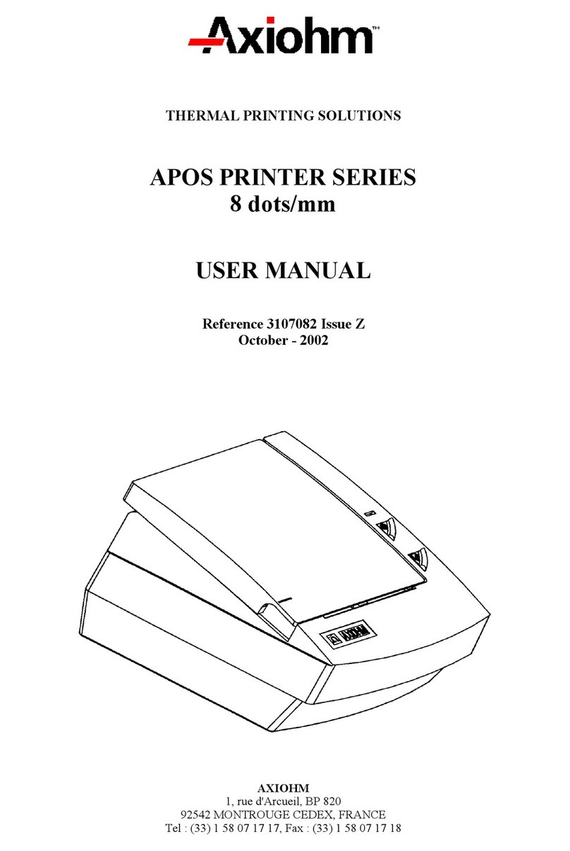
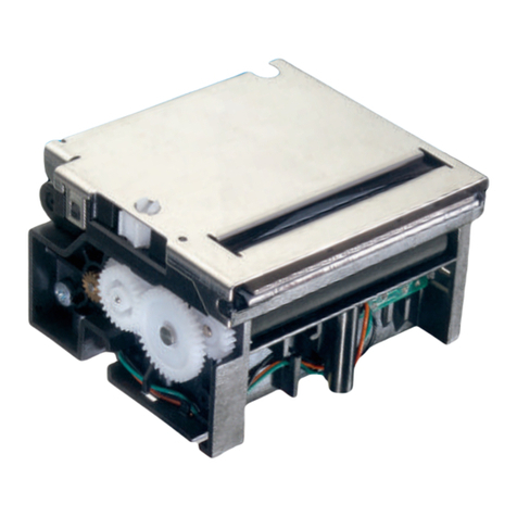
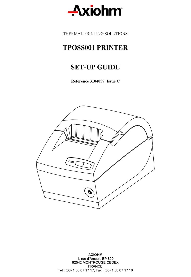
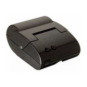
Axiohm Astrium User manual

AXIOHM
1, rue d'Arcueil, BP 820
92542 MONTROUGE CEDEX
FRANCE
Tel : (33) 1 58 07 17 17, Fax : (33) 1 58 07 17 18
THERMAL PRINTING SOLUTIONS
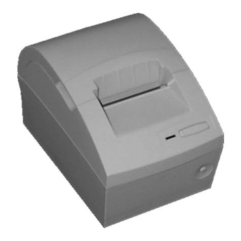
ASTRIUM PRINTER
USER MANUAL
Reference: 3108343 - Issue A

Astrium Printer User Manual 1 / 142 Reference : 3108343 - Issue A
E
EV
VO
OL
LU
UT
TI
IO
ON
NS
S
Date Issue Modifications
02/2005 Z Creation
05/2005 A
Addition of duty cycle and more information about power supply

Astrium Printer User Manual 2 / 142 Reference : 3108343 - Issue A
INTRODUCTION
This single-station (receipt only) thermal printer is addressed to the retail market. Widely used in the
restaurant scenario, this printer model is also highly suitable for a number of other applications ranging
from newspaper agents to department stores, specialty stores and certain supermarkets.
Among the outstanding features this receipt-only printer model has to offer is a Clamshell-type opening
(for simplified paper roll loading), a very small footprint, an incorporated cutter the possibility of dual-
color printing, an interchangeable interface slot and a drawer kick-out connector.
The printer can be installed vertically (so the paper is output frontward) or horizontally (so the paper is
output upwards).
The following options are available:
a. Slot-pluggable interfaces:
1. RS232 C serial (female 25-pin connector)
2. RS232 C serial (female 9-pin connector) with RJ display
connector
3. USB with RJ display connector
4. Bi-directional PARALLEL
b. Wall mounting bracket (vertical position)
c. Kit for using 58 and 60 mm wide paper rolls
d. Spill resistance cover (available on specific request)

Astrium Printer User Manual 3 / 142 Reference : 3108343 - Issue A
CONTENTS
1TECHNICAL SPECIFICATIONS.................................................. 7
2MECHANICAL FEATURES ......................................................... 8
2.1 General description ................................................................................... 8
2.2 Physical characteristics.............................................................................. 8
3INTERFACE BOARD FEATURE ................................................. 9
3.1 Printer location.......................................................................................... 9
3.2 Plugging & Connecting Your Printer ...................................................... 10
3.2.1 Connecting the power supply..................................................... 10
3.2.2 Powering on the printer ............................................................. 12
3.3 Communication’s Management ............................................................... 13
3.3.1 USB Interface Board ................................................................. 13
3.3.2 Parallel Interface Board ............................................................. 13
3.3.3 Serial Interface Board................................................................ 14
3.3.3.1 Serial Interface Board Pinouts.................................................... 14
3.3.4 Installation Procedure................................................................ 16
3.3.4.1 Display connector ..................................................................... 17
3.3.4.2 Drawer driver ........................................................................... 17
3.4 Software components and tools................................................................ 18
3.5 Main functional modules ......................................................................... 18
3.5.1 Printing module ........................................................................ 18
3.5.2 Cutter....................................................................................... 19
3.5.3 Main board............................................................................... 19
3.5.4 Slot-pluggable interface............................................................. 19
3.5.5 External power supply............................................................... 19
3.6 Paper Specifications ................................................................................ 20
3.7 Print specification.................................................................................... 20
3.7.1 Printable area............................................................................ 21
3.7.2 Character specifications............................................................. 22
3.7.3 Printing speed........................................................................... 22
3.7.4 Character sets ........................................................................... 22
3.7.5 Printable character sets .............................................................. 23
3.7.6 Printable character set tables ...................................................... 24
3.7.6.1 Codepage 210 (Greek)............................................................... 24
3.7.6.2 Codepage 437 (International)..................................................... 25
3.7.6.3 Codepage 850 (Multilingual) ..................................................... 26
3.7.6.4 Codepage 852 (Latin 2) ............................................................. 27
3.7.6.5 Codepage 857 (Turkish) ............................................................ 28
3.7.6.6 Codepage 858 (Multilingual Latin I + Euro)................................ 29
3.7.6.7 Codepage 860 (Portuguese) ....................................................... 30
3.7.6.8 Codepage 862 (Hebrew)............................................................ 31
3.7.6.9 Codepage 863 (Canadian-French) .............................................. 32
3.7.6.10 Codepage 864 (Arabic).............................................................. 33
3.7.6.11 Codepage 865 (Nordic) ............................................................. 34
3.7.6.12 Codepage 866 (Russian)............................................................ 35
3.7.6.13 Codepage WPC 1251 (Cyrillic).................................................. 36
3.7.6.14 Codepage WPC 1252 (Latin I)................................................... 37
3.7.6.15 Codepage WPC 1253 (Greek).................................................... 38
3.7.6.16 Codepage WPC 1254 (Turkish).................................................. 39
3.7.6.17 Codepage WPC 1255 (Hebrew) ................................................. 40
3.7.6.18 Codepage 1257 (Baltic)............................................................. 41
3.7.6.19 Codepage 255 (Space page) ....................................................... 42
3.7.6.20 National variants....................................................................... 43

Astrium Printer User Manual 4 / 142 Reference : 3108343 - Issue A
4CONFIGURATION MENU.......................................................... 44
4.1 Printer setup and self printing modes ...................................................... 44
4.1.1 Introduction.............................................................................. 44
4.1.2 Printer Configuration Menu ....................................................... 44
4.1.3 Self Test................................................................................... 45
4.1.3.1 SET UP ........................................................................................ 46
4.1.3.2 Button Functions in the Setup Mode ............................................... 47
4.1.3.3 Navigating through Printer Setup ............................................... 48
4.1.3.4 Notes and Meaning of the Parameters/ List of parameters that can
be changed ............................................................................... 52
4.1.3.5 How to select the parameters .......................................................... 54
4.1.4 Hex-Dump ............................................................................... 54
5. COMMAND DESCRIPTION ....................................................... 55
5.1 Introduction ............................................................................................ 55
5.2 List of control codes................................................................................. 56
5.3 List of TM-T88III Series Emulation Environment................................... 58
5.4 List of TM-T90 Series Emulation Environment ....................................... 59
5.5 Commands .............................................................................................. 60
5.5.1 Explanation of Terms................................................................ 60
5.5.2 Command conventions (AXIOHM)............................................ 61
6. COMMANDS FUNCTION........................................................... 62
6.1 Reset Commands..................................................................................... 62
INITIALIZE PRINTER ............................................................................. 62
6.2 Paper Cut Commands ............................................................................. 63
SELECT CUT MODE.............................................................................. 63
SELECT CUT MODE AND CUT PAPER ............................................... 63
6.3 Vertical positioning and print commands ................................................ 64
PRINT AND RETURN TO STANDARD MODE IN PAGE MODE.......... 64
PRINT AND LINE FEED......................................................................... 64
PRINT AND CARRIAGE RETURN ........................................................ 64
SELECT DEFAULT LINE SPACING ...................................................... 65
SET LINE SPACING............................................................................... 65
PRINT AND FEED PAPER..................................................................... 66
PRINT AND FEED NLINES................................................................... 66
6.4 Horizontal positioning commands............................................................ 67
HORIZONTAL TAB................................................................................. 67
SET ABSOLUTE PRINT POSITION ...................................................... 68
SET HORIZONTAL TAB POSITIONS.................................................... 69
SET RELATIVE PRINT POSITION ........................................................ 70
SELECT JUSTIFICATION ...................................................................... 71
SET LEFT MARGIN................................................................................ 71
SET PRINTING AREA WIDTH............................................................... 72
SET HORIZONTAL AND VERTICAL MOTION UNITS.......................... 73
6.5 Print characteristics commands............................................................... 74
SET RIGHT-SIDE CHARACTER SPACING .......................................... 74
SELECT PRINT MODE(S) ..................................................................... 74
TURN UNDERLINE MODE ON/OFF ..................................................... 76
TURN WHITE/BLACK REVERSE PRINTING MODE ON/OFF ............. 76

Astrium Printer User Manual 5 / 142 Reference : 3108343 - Issue A
TURN EMPHASIZED MODE ON/OFF................................................... 77
TURN DOUBLE-STRIKE MODE ON/OFF ............................................. 77
TURN 90° CLOCKWISE ROTATION MODE ON/OFF .......................... 78
TURN ON/OFF UPSIDE-DOWN PRINTING MODE.............................. 79
SELECT CHARACTER SIZE ................................................................. 80
SELECT CHARACTER STYLE (ONLY TM-T90 EMULATION)............. 81
(FUNCTION 48)...................................................................................... 81
TURNS SMOOTHING MODE ON/OFF.................................................. 81
6.6 Graphics commands ................................................................................ 82
SELECT BIT-IMAGE MODE................................................................... 82
PRINT RASTER BIT IMAGE .................................................................. 84
6.7 Font commands ....................................................................................... 85
SELECT AN INTERNATIONAL CHARACTER SET .............................. 85
SELECT CHARACTER CODE TABLE .................................................. 86
SELECT/CANCEL USER-DEFINED CHARACTER SET ...................... 87
DEFINE USER-DEFINED CHARACTERS ............................................ 88
CANCEL USER-DEFINED CHARACTERS ........................................... 91
SELECT CHARACTER FONT ............................................................... 91
6.8 Logo commands ...................................................................................... 91
DEFINE DOWNLOADED BIT IMAGE .................................................... 91
CUSTOMIZE NV MEMORY AREA (ONLY TM-T90 EMULATION) ....... 93
(FUNCTION 1)........................................................................................ 93
(FUNCTION 2)........................................................................................ 93
(FUNCTION 6)........................................................................................ 94
SELECT GRAPHICS DATA (ONLY TM-T90 EMULATION) .................. 95
(FUNCTION 48)...................................................................................... 96
(FUNCTION 50)...................................................................................... 96
(FUNCTION 51)...................................................................................... 96
(FUNCTION 64)...................................................................................... 97
(FUNCTION 65)...................................................................................... 98
(FUNCTION 66)...................................................................................... 98
(FUNCTION 67)...................................................................................... 99
(FUNCTION 69).................................................................................... 100
(FUNCTION 112).................................................................................. 100
PRINT DOWNLOADED BIT IMAGE .................................................... 101
PRINT NV BIT IMAGE.......................................................................... 102
DEFINE NV BIT IMAGE ....................................................................... 103
6.9 Printer configuration, identification ...................................................... 105
EXECUTE TEST PRINT....................................................................... 105
6.10 Printer status commands ....................................................................... 105
TRANSMIT PRINTER ID ...................................................................... 106
TRANSMIT STATUS ............................................................................ 108
ENABLE/DISABLE AUTOMATIC STATUS BACK (ASB) .................... 109
6.11 Real time commands.............................................................................. 113
REAL TIME STATUS TRANSMISSION ............................................... 113
GENERATE PULSE AT REAL TIME ................................................... 115
REAL TIME REQUEST TO PRINTER ................................................. 116
6.12 Bar code commands............................................................................... 117
SELECT PRINTING POSITION OF HRI CHARACTERS .................... 117
SELECT BAR CODE HEIGHT ............................................................. 117
PRINT BAR CODE SECOND VARIATION .......................................... 118
SELECT BAR CODE WIDTH ............................................................... 122
SELECT FONT FOR HUMAN READABLE INTERPRETATION
(HRI) CHARACTERS ........................................................................... 122
6.13 Peripheral control command ................................................................. 123
GENERATE PULSE ............................................................................. 123
ISSUES AN AUDIBLE SIGNAL ............................................................ 123
SELECT PERIPHERAL DEVICE ......................................................... 123
ENABLE/DISABLE PAPER END SIGNAL ........................................... 124
6.14 Page Mode commands ........................................................................... 125
Astrium Printer User Manual 6 / 142 Reference : 3108343 - Issue A
PRINT DATA IN PAGE MODE............................................................. 125
SELECT PAGE MODE ......................................................................... 125
SELECT STANDARD MODE ............................................................... 126
SELECT PRINT DIRECTION IN PAGE MODE ................................... 127
SET PRINTING AREA IN PAGE MODE .............................................. 127
SET ABSOLUTE VERTICAL PRINT POSITION IN PAGE MODE ...... 129
SET RELATIVE VERTICAL PRINT POSITION IN PAGE MODE ........ 129
6.15 Macro commands .................................................................................. 130
CANCEL PRINT DATA IN PAGE MODE ............................................. 130
SELECT PAPER SENSOR(S) TO STOP PRINTING .......................... 131
ENABLE/DISABLE PANEL BUTTONS ................................................ 131
START/END MACRO DEFINITION ..................................................... 132
EXECUTE MACRO .............................................................................. 132
7. CONTROL PANEL................................................................... 133
7.1 Buttons .................................................................................................. 133
7.2 LEDS..................................................................................................... 133
8. OTHER INFORMATION........................................................... 134
8.1 Printing and Paper Feeding ................................................................... 134
8.2 Safety precautions and general operating norms ................................... 135
8.3 Loading the thermal paper roll.............................................................. 135
8.4 Adjusting the near paper end sensor...................................................... 136
9. TROUBLESHOOTING ............................................................. 137
10.CLEANING YOUR PRINTER................................................... 138
11.TRANSMISSION STATUS IDENTIFICATION ......................... 139
12.PAGE MODE............................................................................ 140
12.1 Introduction .......................................................................................... 140
12.2 Setting Values in Standard and Page Modes .......................................... 140
12.3 Formatting of Print Data in the Printable Area ..................................... 140

Astrium Printer User Manual 7 / 142 Reference : 3108343 - Issue A
1TECHNICAL SPECIFICATIONS
The following table gathers the main characteristics of the printing unit.
ITEM VALUE UNIT
Technology Direct thermal -
Printing resolution 203 dpi/8 dots per mm (8 dots per mm)
Resolution of the received bitmaps 203 x 203 dpi -
Character size Font A: 1.41(W) x 3.39(H)
Font B: 0.99 (W) x 2.40 (H) mm
Character sets Font A (predefined): 15 cpi,
Font B: 20 cpi -
Print field 72 mm, 576 dots -
Speed Up to 200 mm/s
Columns Font A: 42 / Font B: 56 -
Paper loading Clamshell TH -
Receipt width 80 mm
Paper roll diameter Up to 100 mm
Roll core diameter Internal: 12.7, External: 18
(suggested) mm
Cutter Automatic (partial cut), manual
(with tear bar) -
User Flash memory 384 KBytes
Data reception buffer 4 Kbytes / 45 bytes
Interface
(according to version)
Mutually exclusive, available
on a slot pluggable interface
board:
- RS 232 C (25-pin connector),
- RS 232 C (9-pin connector +
display connector),
- Bi-directional parallel,
- USB (with display connector)
- Ethernet soon available
-
Dimensions (WxDxH) 140 x 217 x 157 mm
Weight About 1.9 Kg
Temperature Operating: +10 to 40 °C,
Storage: -15 to 40 °C °C
Humidity
Operating: HR 20 to 85% (non-
condensing)
Storage: HR 5 to 90% (non-
condensing)
-
Power supply:
- Input
- Output
Power consumption:
- Standby
- Operating
100 - 240
50 – 60
24
72
< 5
36 (average)
V
Hertz
V DC
Watt
Watt
Watt
Power supply unit
External (110/240 Vac, 50-60
Hz), with detachable power
cord
Hertz

Astrium Printer User Manual 8 / 142 Reference : 3108343 - Issue A
2MECHANICAL FEATURES
2.1 General description
ON/OFF
OPEN
FEED
ON
ROLL
ERR
2.2 Physical characteristics
Width: 140 mm
Depth: 217 mm
Height: 157 mm
Weight: 1.9 Kg
Horizontal installation Vertical installation
OPEN

Astrium Printer User Manual 9 / 142 Reference : 3108343 - Issue A
3INTERFACE BOARD FEATURE
3.1 Printer location
Installing the printer horizontally or vertically so the paper is expelled upward, or vertically so the paper is
expelled from the front.
EXTERNAL VIEW
Horizontal Installation Vertical Installation
Paper output slot
Operating console
Operating console
Paper output slot
INTERNAL VIEW
Automatic cutter
counter blade
Printhead
Manual
cutter
Printer cover
Automatic cutter
blade Paper feed roller
Paper roll compartment
Almost out of paper
sensor adjustment

Astrium Printer User Manual 10 / 142 Reference : 3108343 - Issue A
3.2 Plugging & Connecting Your Printer
3.2.1 Connecting the power supply
Unpack the printer and all its components. Open the printer cover by pressing the Open button on the
operating console as far as it goes (until hearing a click sound indicating that the button is locked in a
pressed position) and then remove the piece of cardboard protecting the print head.
Position the printer vertically and then open and remove the rear connectors’ cover by releasing its
snap hook, using a screwdriver, and lifting it off. Plug the interface cables into the related connectors on
the printer and then route the cables through the cable blocks (A) to prevent accidental disconnections.
Tighten the securing screws, if present, of the interface cable connectors.
A
Drawer
Display
(if available)
Plug the power cord of the external power supply unit into printer power jack (B). Attach one end of
the power cord, provided with the printer, into the related connector (C) on the external power supply
unit.
B
C

Astrium Printer User Manual 11 / 142 Reference : 3108343 - Issue A
Using a screwdriver, remove extractable parts (D) so that you can then route the cables externally
according to your needs. Ensure that the passage slots are completely clear of any plastic protrusion that
could damage the cables.
WARNING: Once removed, the extractable parts cannot be reattached.
D
D
D
D
D
Refit the connectors’ cover by inserting the cover’s lower and upper tabs into the corresponding slots
(E) and (F), routing the cables through the passage slots that were opened in the previous step.
F
E
E
VIEW BEHIND THE CONNECTORS’ COVER
Power supply jack
Drawer interface
Open
connector’s
cover
Mutually exclusive
interface (available on slot
pluggable interface card):
- Bi-directional parallel
- Serial (25-pin)
- USB
- Serial (9-pin)
Display interface
available with the
following interfaces:
Serial (9-pin) and USB
Make sure that the printer and all the devices connected to it are powered off and then insert the free
end of the power cord into the electrical power outlet.
Power on the printer as explained in the section Powering On the Printer.
Load the paper roll as explained in the section Loading the Thermal Paper Roll.

Astrium Printer User Manual 12 / 142 Reference : 3108343 - Issue A
3.2.2 Powering on the printer
Ensure that the printer’s external power supply unit is attached to an easily accessible electrical
power outlet.
Press the ON/OFF button on the operating console.
NOTE: Under normal operating conditions only the green power (ON/OFF) LED should be on when the
printer is powered on. Therefore if the LED on the operating console indicate a different machine status,
refer to the troubleshooting section for the related corrective actions.
Button Functions and LED States
BUTTON/
LED DESCRIPTION
ON/OFF
( )
Press once to power on the printer.
With the printer powered on, press for more than
2 seconds to power it off.
OPEN Press to unlock the printer cover so that it can be
opened.
FEED ( )
Press once to advance the paper one line feed.
Press and hold down to feed the paper
continuously.
ON ( )
When off: Printer powered off.
When on green: Printer powered on.
When flashing green: Thermal print head
overheated, printer busy.
ERR ( )
When off: Printer in normal operating
conditions.
When on red: Paper jam, cutter locked, printer
failure.
ROLL ( )
When off: Printer loaded with paper.
When on yellow: Printer almost out of paper.
When flashing yellow: Printer out of paper.

Astrium Printer User Manual 13 / 142 Reference : 3108343 - Issue A
3.3 Communication’s Management
This section explains how to install slot-pluggable interface boards on this printer model. One of the
following slot-pluggable interface boards can be installed:
1. 9-pin or 25-pin RS232 serial
2. USB
3. Bi-directional parallel
WARNING: Before proceeding with any type of operation, unplug the power cord of the external power
supply unit from the electrical power outlet and bear in mind the information provided in the section of this
manual entitled Safety Precautions and General Operating Norms.
3.3.1 USB Interface Board
The following figure shows the USB interface board that can be installed.
USB Interface Board
See page 1-9 of this manual for the Display Output Connector pinout.
3.3.2 Parallel Interface Board
The following figure shows the parallel interface board that can be installed on the printer.
Parallel Interface Board
Display connector

Astrium Printer User Manual 14 / 142 Reference : 3108343 - Issue A
3.3.3 Serial Interface Board
The following 9-pin or 25-pin serial interface board can be installed on the printer.
9-Pin 25-Pin
3.3.3.1 Serial Interface Board Pinouts
9-pin and 25-pin Serial Interfaces
The table below gives the pinouts of the 9-pin and 25-pin serial interfaces.
9-Pin Serial
25-Pin Serial
1 Not used 1 GND
2 RxD 2 TxD
3 TxD 3 RxD
4 DTR 4 RTS
5 GND 5 CTS
6 DSR 6 DSR/Reset (According to jumper configuration)
7 RTS 7 GND
8 CTS 8 Not used
9 Not used 9 - 19 Not used
20 DTR
21 - 24 Not used
25 Reset (According to jumper configuration)
Display connector

Astrium Printer User Manual 15 / 142 Reference : 3108343 - Issue A
Configuring the Serial Interface Board
Before installing the board, you need to configure the jumpers accordingly. Refer to the information
provided in the tables below.
9-pin Serial
INSTALLED (ON) I/F pin 6 used as Reset signal
NOT INSTALLED (OFF) I/F pin 6 used as DSR signal
When the jumper is installed, the printer is reset when the signal remains MARK for 1 ms or more.
25-pin Serial
INSTALLED (ON) I/F pin 6 used as Reset signal
Jumper J2 NOT INSTALLED (OFF) I/F pin 6 used as DSR signal
INSTALLED (ON) I/F pin 25 used as Reset signal
Jumper J3 NOT INSTALLED (OFF) Not used
When jumper J3 is installed, the printer is reset when the signal remains SPACE for 1 ms or more.
Jumper
Jumper
Jumper J3

Astrium Printer User Manual 16 / 142 Reference : 3108343 - Issue A
3.3.4 Installation Procedure
Provided below is the procedure for installing an interface board. This procedure applies to both
slot-pluggable interface boards available.
•Unscrew the two screws Aand extract the old board from its slot.
•Insert the new board into the slot, pushing it as far as it goes. Ensure that it plugs correctly with the
related connector on the main board. Secure the board in place by tightening the two screws A.
The printer FW will automatically detect the new board installed.
A

Astrium Printer User Manual 17 / 142 Reference : 3108343 - Issue A
3.3.4.1 Display connector
Slot-pluggable Interface boards (9-pin RS 232 and USB) are available with Display connector.
Pinout of the Display Output Connector
1 Safety ground
2 Transmit data to print
3 Receive data from printer
4 Indicates whether the printer can receive data or not
5 Indicates whether the display can receive data or not
6 Signal ground
7 Power supply terminal
8 Power supply retrace line
Note: The signal Transmitted Data (pin 2) is not connected; the signal Data Set Ready
(pin 4) is always in ON state, by means of a pull-up resistor.
For this reason, both signals are not included in the printer display data exchange.
3.3.4.2 Drawer driver
A drawer connector is resident on the main board.
Output connector:
1 Frame ground
2 Drawer kick-out drive signal
3 Drawer open/close signal
4 + 24 V
5 Drawer kick-out drive signal
6 Signal ground
The driver for the drawers controls two solenoids and a drawer open/closed sensor, with the following
characteristics:
Drawer drive signals
Output signals: approximately +24V
Maximum current: 1A
The timing of the drive signals for drawers 1 and 2 can be controlled via software using the ESC p m n1
n2 with the following parameters:
m= 0 drive signal pin 2
m= 1 drive signal pin 5
n1 x 2 msec defines the ON timing (for details refer to the SW commands)
n2 x 2 msec defines the OFF timing.
Warning:
To prevent an overcurrent condition, the drawer solenoid must have a resistance of 24 Ohms or greater.
Note:
•To connect the drawer, use a shielded cable.
•The two drive transistors should not be energized simultaneously. Use pin 4 to power the drawer.
•The resistance of the drawer solenoid must not be below the specified value otherwise an overcurrent
could damage this component.
Resistance of solenoids 24 ohm min
Output voltage 24 volts
Current 1 amp max.
Printer side connector Molex 52065-6615

Astrium Printer User Manual 18 / 142 Reference : 3108343 - Issue A
3.4 Software components and tools
The software includes the following components:
•Printer Driver: Standard Windows printer driver.
•Opos: A standard component that enables other components to use the printer. It includes:
-Opos for POS printers
-Opos for Cash Drawer
-Opos for Line Display
•Tool Kit: A set of utilities required for printer management. It includes:
-Firmware downloader
-Setup configurator
-Logo downloader
-Memory maintenance
•POS-RKserver: DCOM component (to drive and program the printer remotely using the Resource
Kit).
•Demo: Demo program
•Installation Kit: for installing the program.
3.5 Main functional modules
The printer is made up of the following main modules:
-Printing module
-Cutter
-Main board
-Slot-pluggable interface
-External power supply
3.5.1 Printing module
The thermal printer module prints directly on thermal paper. It is equipped with a single 72 mm optimized
thermal print head with the following characteristics:
–Heat Element Structure 2 Heaters/dot
–Number of Heat Elements 576 dots
–Heat Element Pitch 0.125 mm (8.0 dots/mm)
–Print Width 72 mm + 0.2 mm
It prints horizontally at 203 dpi (8 dots/mm).
The printing module has the following electronic sensors:
•Near end of paper
-Detection method: microswitch
-Almost out of paper detection adjustment: Via adjustment lever
When the diameter of the paper on the roll is nearly reaching the core, the sensor detects the almost
out of paper condition and lights up a yellow LED on the operator console. If the sensor is enabled
(by ESC c 4), printing is interrupted.
oSuggested paper roll core diameter is:
internal 12.7 mm (0.5")
external 17.7 mm (0.7")

Astrium Printer User Manual 19 / 142 Reference : 3108343 - Issue A
•Paper detection sensor
-Detection method: photosensor
-The paper detection sensor is installed on the paper path and detects the presence of the paper when
its light rays are beamed back by the paper installed. This photosensor is adjusted via console (refer
to the adjustment procedure).
The flashing of a yellow LED on the operator console signals the out of paper condition.
•Cover Open
-Detection method: photosensor
This sensor automatically interrupts printing when the cover is opened. Close the cover to restore the
normal operating conditions.
3.5.2 Cutter
•Cutting method: rotating blades.
•Type of cut: partial (an uncut border of 3.5 mm remains on the right-hand side if the printer is installed
horizontally, on the left-hand side if it installed vertically).
•The receipt can also be cut manually by the operator.
The cutter mechanism is equipped with a photosensor that detects the home position of the cutter blades
when the printer is powered on and after the cutting of the receipt. If the cutter blades are not repositioned
correctly to their home position, the red Error LED on the console will begin to flash.
3.5.3 Main board
•Slot interface: 16-bit bus
•CPU: 16 MHz H8S – 2633
•Programmable gate array: CPLD XILINX XC9536
•RAM Base: 64Kx16 byte
•Firmware: 1 M byte Flash (512 x 16)
3.5.4 Slot-pluggable interface
Four different interface boards can be installed on the printer:
1. Serial RS232 C (female 25 pin connector)
2. Serial RS232 C (female 9 pin connector) with RJ display connector
3. USB with RJ display connector
4. PARALLEL bi-directional
The printer automatically recognizes the type of interface installed.
3.5.5 External power supply
•Switching type
•Input voltage: 110 – 220 Vac
•Output voltage: 24 Vdc
Table of contents
Other Axiohm Printer manuals

Axiohm
Axiohm A758 User manual

Axiohm
Axiohm A758 User manual

Axiohm
Axiohm A795 User manual

Axiohm
Axiohm TPOS PRINTER SERIES User manual

Axiohm
Axiohm TELESTO User manual

Axiohm
Axiohm APM-90 User manual

Axiohm
Axiohm A721 User manual

Axiohm
Axiohm 7156 User manual

Axiohm
Axiohm APOS PRINTER SERIES User manual

Axiohm
Axiohm A794 User manual

Axiohm
Axiohm A630 User manual

Axiohm
Axiohm 7193 User manual

Axiohm
Axiohm PCPR Printer User manual

Axiohm
Axiohm 24V User manual

Axiohm
Axiohm CMBC-XMBC User manual

Axiohm
Axiohm A220 User manual

Axiohm
Axiohm TPOSS001 User manual

Axiohm
Axiohm A795 User manual

Axiohm
Axiohm SKGG5xxx Series User manual

Axiohm
Axiohm A794-D100 User manual