GRASS GRASS ECOPRESS User manual

The star in your cabinet
GRASS ECOPRESS
OPERATING INSTRUCTIONS
Ecopress-Pneumatic / Ecopress-Manual

2
Technical Data
The star in your cabinet
Technical Data
Dimensions:
Width of machine table 720 mm
Depth of machine table with bore distance 20 mm 300 mm
Height of machine table 75 mm
Total height of machine 665 mm
Total depth of machine 455 mm
Other data:
Press force of 0,6 MPa ( 6 bar ) about 2800 N
Weights:
Total weight of the Ecopress-Pneumatic standard equipment 45 Kg
Total weight of the Ecopress-Manual standard equipment 36 Kg
Electric Connections:
Voltage according to the identification plate ........ V
Frequency according to the identification plate ........ Hz
Connection capacity of 3 phase motors 1,5 kW
Connection capacity of 1 phase motors 1,1 kW
Power of the supply line according to the local codes and regulations, but at least 1.5 mm 2
Securing the supply line with a maximum 1.5 x nominal current according to the identification
plate with a maximum, nevertheless of 16 A.
Pneumatic Connections (only with Ecopress-Pneumatic):
Dustfree, waterfree and oilfree air pressure at least 5,5 bar
Maximum allowable pressure in supply line 10,0 bar
Air pressure usage per stroke motion with 6 bar 1,25 l
Air pressure usage per stroke motion,
Suction capacity for compressor 7,5 l
Other connections (only with Ecopress-pneumatic):
Dust collection: connecting diameter Ø 80 mm
Suction capacity about 2000 m3/h
Emission values:
Noise level in neutral 92,6 dB/A
Noise level during drilling 93,8 dB/A
Dust emission in the air with the Ecopress-Pneumatic 0,48 mg/m3
For details on emission values, see chapter 3-001

3
Table of contents
The star in your cabinet
Page
1. General information 5-6
1-001 List of illustrations 5
1-002 Manufacturer 6
1-003 Copyright 6
1-004 Terms of guarantee 6
2. Safety Information 7-9
2-001 Safety information 7
2-002 Recommended usage 7
2-003 Risks according to EN 292-2 8
2-004 Safety devices 8
2-005 Description of stickers 8
2-006 Dangers and safety measures 9
3. Product Description 10-13
3-001 Dust and noise emission values 10
3-002 Usage 11
3-003 Identification of products 11
3-005 Standard equipment 11
3-006 Standard accessories 12-13
4. Maschine - Parts Description 14-28
4-001 Overview of assembly group numbering 14-15
4-002 Description of the individual assembly groups 16-21
4-003 Gear box - Hole line boring of the Ecopress 22-23
4-004 Description of the operating elements 24-25
4-005 Machine’s function 25
4-006 Pneumatic wiring diagram 26-27
4-007 Elektric wiring diagram 28-29
5. Shipping and Installation of Machines 30-32
5-001 Transport and storage requirements 31
5-002 Space and environmental requirements 31
5-003 Unpacking and installing in the designated place of destination 30-32
6. Start - Up 33
6-001 Pneumatic connection 33
6-002 Elektric connection 33
6-003 Other connections 33
7. Operating the Ecopress 34-65
7-1 Requirements for operators 35
7-2 Setting-up the Ecopress 34-39
7-201 Installing the drill bit into the drill chuck on the Ecopress 34-35
7-202 Installing an insertion die 34-35
7-203 Installing a hole line boring gear box 36-37
7-204 Installing a pendulum stop 38-39

4
Table of contents
The star in your cabinet
Page
7. Operating the Ecopress 34-65
7-3 Adjusting the Ecopress 40-49
7-301 Adjusting the boring depth 40-41
7-302 Adjusting the boring distance 40-41
7-303 Adjusting the boring speed of the Ecopress-Pneumatic 42-43
7-304 Adjusting the turn-on time of the E-Motor with the Ecopress-Pneumatic 42-43
7-305 Adjusting the turn-on time of the E-Motor with the Ecopress-Manual 44-45
7-306 Adjusting the side stops 44-45
7-307 Operating the stop adjustment gauge 46-47
7-308 Operating the index ruler ( accessory) 48-49
7-309 Adjusting the hold down clamps ( accessory ) 48-49
7-4 Examples of Usage 50-65
7-401 Drilling and inserting the Grass Hinge System 1000/3000/4000 50-51
7-402 Drilling and inserting the Grass Baseplate System 1000/3000 52-53
7-403 Drilling the hole line borings ( only with accessories ) 54-55
7-404 Drilling the fronts for Grass Zarge System 6000/7000 56-57
7-405 Drilling the back panels for Grass Zarge System 6000/7000
( only with accessories ) 58-59
7-406 Drilling and inserting visible hinges 60-61
7-407 Drilling and inserting fastening hardware 62-63
7-408 Drilling of handle bore holes ( only with accessories ) 64-65
8. Trouble Shooting and Problem Solving 66-69
8-001 Incorrect boring distance - adjustment of scale 66-67
8-002 Boring speed cannot be adjusted 67
8-003 Motor does not run 67
8-004 Boring head does not descend 69
8-005 Parts do not fit the drill patterns when inserted 68-69
9. Maintenance and Care 70
9-001 Maintenance plan 70
9-002 Maintenance and care information 70
10. Miscellaneous 71-80
10-001 Guarantee certificate 71-72
10-002 Disposal form 73-74
10-003 Resale form 75-76
10-004 Questionnaire 1 77-78
10-005 Questionnaire 2 79-80
10-006 List of Grass distributors 81

5
1. General Information
The star in your cabinet
1-001 List of Illustrations
Illustration Description Page
3-006 Miscellaneous standard accessories 12
4-001-01 Overall view of the Ecopress-Pneumatic 14
4-001-02 Overall view of the Ecopress-Manual 14
4-002-01 Machine table 16
4-002-02 Motor support 16
4-002-03 Machine frame of the Ecopress-Pneumatic 18
4-002-04 Machine frame of the Ecopress-Manual 18
4-002-05 Electrical switch box of the Ecopress-Pneumatic 20
4-002-06 Electrical switch box of the Ecopress-Manual 20
4-003-01 Hole line boring - Standard gear box 22
4-003-02 Hole line boring 5-spindle hole line boring gearbox 22
4-004-01 Operating features of the Ecopress-Pneumatic 24
4-004-02 Operating features of the Ecopress-Manual 24
4-006-01 Pneumatic wiring diagram for the Ecopress-Pneumatic 26
4-007-01 Electric wiring diagram 28
5-003-01/..../04 Assembly of the Ecopress 30
5-003-05/..../10 Mounting the hand lever of the Ecopress-Manual 32
7-201-01 Mounting the drill bit 34
7-202-01/02 Mounting the insertion die 34
7-203-01/..../04 Mounting the 5-spindle hole line boring gearbox 36
7-204-01/..../04 Mounting the pendulum stop 38
7-301-01 Adjusting the boring depth 40
7-302-01 Adjusting the boring distance 40
7-303-01 Adjusting the boring speed with the Ecopress-Pneumatic 42
7-304-01 Adjusting the turn-on time of the E-Motor with the Ecopress-Pneumatic 42
7-305-01 Adjusting the turn-on time of the E-Motor with the Ecopress-Manual 44
7-306-01 Adjusting the side stops 44
7-307-01.../03 Operating the stop adjustment gauge 46
7-308-01 Operating the index ruler 48
7-309-01 Adjusting the pneumatic hold down clamps 48
7-401-01/02 Drilling and inserting the Grass hinges 50
7-402-01/02 Drilling and inserting the Grass baseplates 52
7-403-01/02 Drilling the hole line borings 54
7-404-01/02 Drilling the fronts 56
7-405-01/02 Drilling the back panels 58
7-406-01/02 Drilling and inserting the visible hinges 60
7-407-01/02 Drilling and inserting fastening hardware 62
7-408-01/02 Drilling of handle bore holes 64
8-001-01 Adjusting the boring distance scale 66
8-005-01/02 Adjusting the insertion arm 68

6
1. General Information
The star in your cabinet
1-002 Manufacturer
Grass GmbH Tel. +43/(0)5578/701-0
Grass Platz 1 Fax. +43/(0)5578/701-59
6973 Hoechst Internet: http://www.grass.at/
Austria
1-003 Copyright
The manufacturer has the exclusive copyright. Any means of copying is permitted only with the
permission of the manufacturer, unless the operating instructions are copied for the purpose of
utilizing the machine.
1-004 Terms of the Guarantee
The shipped Ecopress comes with a guarantee that is within the scope of the ”General Terms of
Guarantees in the Association of the Machinery and Steel Construction Industry.” Misuse, repairs by unauthorized or
untrained personnel, usage of unauthorized replacement parts or accessories without written approval from the manu-
facturer invalidate any guarantee claims.
We reserve the right to modify the machine, technically and aesthetically, for whatever reason. When the machine is
shipped from the manufacturing plant, it meets the latest regulations and technical standards.
The manufacturer is under no obligation to modify machines free of charge due to changed regulations, standards or
specifications.
In case of guarantee claims, please contact the authorized Grass representative or an authorized Grass distributor and
give him the machine model and the machine number.
Lists of representatives or distributors are given in chapter 10-006.
Guarantee claims will be honored only if the guarantee certificate was filled out completely and sent to the
manufacturer. The guarantee certificate is in chapter 10-001.
The guarantee or warranty covers only replacement of parts or the repair of defective parts.
Not included in the guarantee are:
- Transportation damages (these damages should be filed with the post office, railway or shipping company)
- Natural wear and tear of parts
- Drill bits
- Damages resulting from negligence of protective rules
- Damages resulting from inappropriate handling or from misuse of the Ecopress
- Damages to the material being worked on
- Replacement of down time
- Wages or money lost due to a defective Ecopress
- Installation time, travel time, and travel expenses.

7
2. Safety Information
The star in your cabinet
2-001 Safety Information
- It is the responsibility of the machine owner or their authorized representative to make certain that the machine
operators are correctly trained in the operation of the machine.
- Only authorized electricians or electrical specialists may work on the electrical equipment.
- The pneumatic and electric connecting lines are to be installed in an orderly manner and are to be protected from
damage (by cable channels, conduits, or something similar).
- The safety devices, which are included in this shipment, must always be utilized and shall not be by-passed or
rendered inoperable.
- During service or maintenance work, the machine must be turned off at the main electrical switch (unplug the
machine) and the machine must be disconnected from the pneumatic lines (for example, by quick coupling).
- Before a tool change, gearbox change or work in the area of the drill, the main switch must always be set at 0.
- Use only tools which meet specifications and regulations and which are strong and durable (such as the tools from
the Grass product line program).
-Only hard metals, or HSS (high speed steel) drills with a total length of 57 mm and a shaft diameter of 10 m may
be utilized.
- The drill diameter may be a maximum of 35 mm on the drive spindle and a maximum of 15 mm diameter on all
the other bore spindles.
- Before operating the machine, all safety devices must be checked to make sure they are complete and function
correctly.
- The operator should be especially careful with larger workpieces that project out over the machine. We strongly
recommend using a larger support base or additional support bases for the workpiece.
- Shavings should not be blown off, but should be suctioned with the appropriate device.
- The machine should always be turned off at the main switch when work is finished and then secured, so that
unauthorized persons cannot start it.
- Keep the workplace and the surrounding area clean because messiness and an unorganized workplace increase
the risk of injury.
- Protect yourself from electrical shocks.
- Utilize the machine only in dry spaces and never leave the machine outside in the rain.
- Keep unauthorized persons away from the machine.
- Only one person shall operate the machine.
- When working, keep your hands away from the working area of the drill and the insertion die arm.
- Wear appropriate work clothing when operating the machine.
- Use a hair net with long hair and do not wear wide or floppy pieces of clothing which could
become caught in moving machine parts.
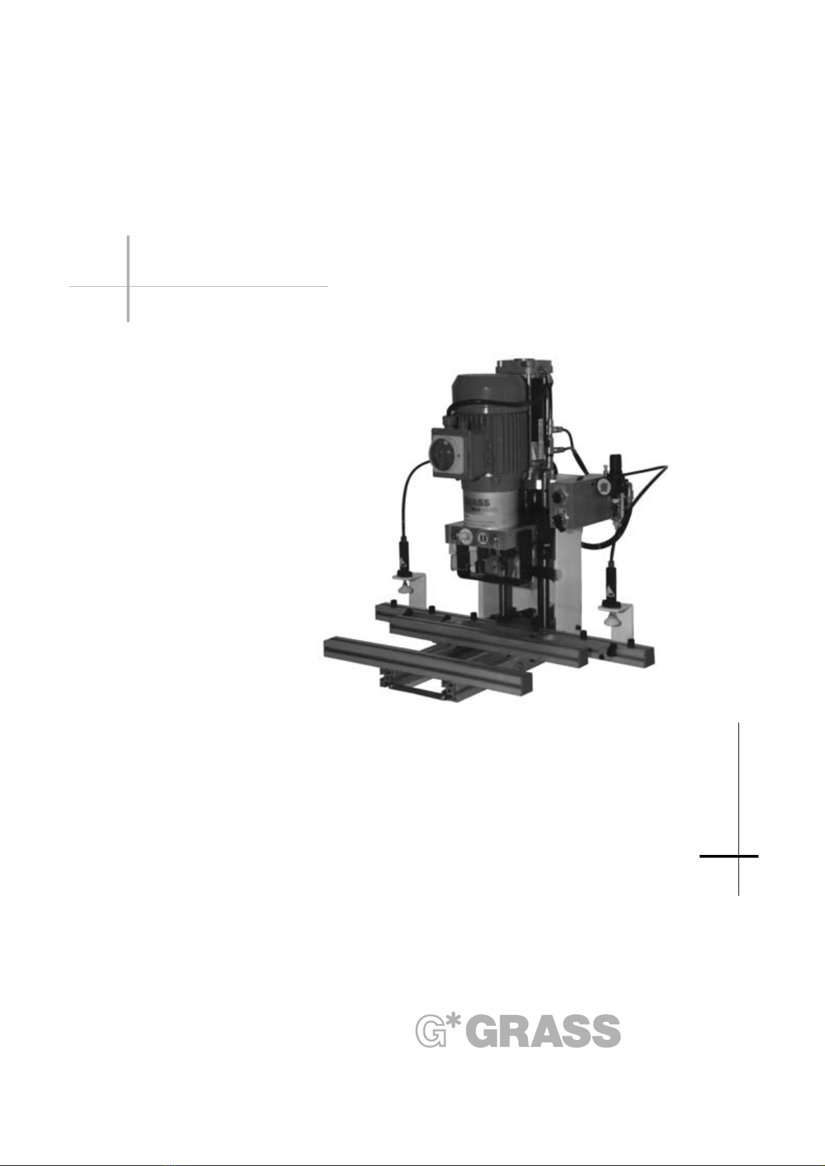
2-002 Recommended Usage
- The Grass Ecopress hinge drilling machine is used exclusively for drilling in solid wood and derived wood materi
als as well as for the purposes described in chapter 7-4 ”Examples of Usage”. Other uses are not specified,
and, thus, the manufacturer is not liable for resulting damages. The operator and user alone assume all risks.
- The operator must conform to the operating instructions when determining appropriate usages.
- The machine shall only be operated, serviced and maintained by trained and authorized personnel
- The original set-up may not be modified without the express consent of Grass GmbH.

8
2. Safety Information
The star in your cabinet
2-003 Risks According to EN 292-2
The Ecopress hinge drilling machine is built according to current state of technology and known
safety and technical directives. Still, risks remain for the life and health of the operator or of
third parties, as well as damage to the machine and other property.
Remaining risks consists of:
- Caution: even when the main switch is turned off, the machine can move if the start button is
activated
- operation of the machine by unqualified personnel
- operation of the machine without the required and recommended safety devices
- inappropriate tooling or improper installation or attachment of tooling
- the placement of the operator’s second hand during drilling, inserting and installing of machine parts
- additional person(s) being in the area of the operating machine
- contact with a machine which has not been turned off and secured in the proper manner
- not maintaining the machine properly as described in chapter 7-0 ”Operating the Ecopress”
- malfunctioning of the control elements.
These remaining risks can be prevented by adhering to the information found in chapter 2-0 and 7-0.
2-004 Safety Devices
Safety devices, information about dangers, etc. serve to ensure safety and may not, in any case be removed or
be made inoperable.
- The main switch, which can be turned off to prevent unauthorized start-ups, must be turned off
during adjustment and set-up processes.
- The pneumatic filter reducing regulator prevents the machine from overloading (see chapter 4-006).
- For thermal overload protection of the motor, see chapter 4-007.
- Controllable back pressure valve, which is directly on the main cyclinder, prevents the machine from descending in
the event the compressed air is lost. The valve is first opened when the start button is activated
(see ”Pneumatic Wiring Diagram” chapter 4-006).
- The motor first runs when the machine is changed from the feed position to the forward operating speed.
- The motor does not run during the insertion.
- The integrated dust collection system protects personnel from fine dust and simultaneously also protects one from
injury by the drill.
2-005 Sticker Description
Information warns that the drill unit may descend even
when the motor is turned off (only with the
Ecopress-Pneumatic).
This sticker indicates EG conformity.
Warning sign that only one person should operate the
machinery at a time.
Warning sign that indicates crushing danger and to keep
hands or other objects clear.
Read operating instructions, as well as information,
thoroughly.
ACHTUNG:
Hubbewegung auch bei
ausgeschaltenem Motor möglich

9
2. Safety Information
The star in your cabinet
2-006 Dangers and Safety Measures
Dangers Safety Measures
Tool releases chuck with clamping screw
Tool breaks use exclusively authorized products
(for example, from the Grass GmbH product line)
Contact with tool all tools are behind transparent covers
Tool - Contact with the machine safety - drilling depth stop
Tool - being thrown out tool stops
Feed mechanism the Ecopress-Manual does not have an
automatic feed motion. It has a manual feed.
Workpiece clamping device reduced pressure (reduced hold down force)
(unless available - accessory)
Risk of impact not applicable, because the stroke motion is slow
Drive the direct drive is completely enclosed
Tool sets forward feed for stroke motion
non self-locking buttons with collar
meet safety margins EN 294 depending on the risks
the Ecopress-Manual has only a manual feed
Control System electrical control with P-E-Wandler, non self-
unexpected tool start locking button with collar,
from feeding speed to motor first runs after being switched on.
operating speed
Control System non self-locking button with collar
unexpected lifting disengagement the Ecopress-Manual has only a manual feed
Control System switch cam
Press to begin tool start
Electricity Equipped according to EN 60204 part 1,
VDE 0100 in accordance with IEC 384
Noise measured emissions values correspond to the
current state of technology; work place
emissions values are under 85 dB (A)
Dust the wood dust emissions fall below limits
with the connected dust collection system
(available only as an accessory with the Ecopress-Manual)

10
3. Product Description
The star in your cabinet
3-001 Noise and Dust Emissions Values
Noise
The noise emissions, according to EN31202 with CEN TC 142 and in relation to the reported ISO 7960 noise
emissions, determine the work place emissions ratings.
LpA = 93,8 dB(A) during drilling
measuring uncertainties constants K are 4 dB/A
The machine’s specific settings during the measuring cycle:
Drillbit: 1 Hinge cup drill bit Ø 35 mm t = 13 mm n=2890U/min.
2 Dowel drill bit Ø 8 mm t = 13 mm n=2940 U/min.
Work piece: uncoated particle board
Microphone’s position 0.5 m in front of the drill motor axle in 1.5 m height
Dust:
The determined dust rating accoring to DIN 33893 Part 2
Statistical protected maximum amount 0,48 mg/m3
Description of the interface exhaust connection piece:
Suction exhaust pipe Ø 80 mm
Minimum air speed 17,9 m/sec.
Static suction 480 Pa
Connection of the Suction System:
The Ecopress must be connected to a suction system according to the interface description.
Hook-up line are to be very inflammable
If an electric coupling is required for the suction system, the Grass company has a special accessory-a volume flow
monitor with the appropriate contacts which are connected as shown in the electrical wiring diagram in chapter 4-007.
Suction Elements:
If the dust and shaving collection elements of the Ecopress system are correctly operated (hook-up according
to interface description), the amount of wood dust falls below the TRK limit values.
The testing procedures for measuring are set forth in the DIN 33893 Part 2 by an independent agency.

11
3. Product Description
The star in your cabinet
3-002 Usage
The Ecopress hinge drilling machine is designed exclusively for only those operations described in chapter 7.4
”Examples of Usage”. The manufacturer guarantees a very smooth and problem free operation for these usages.
Violations or misuse can result in injuries of the machine operators or to damages to the machine or workpieces.
3-003 Product Identification
All machine are provided with an identificaiton plate on which the machine number, manufacturing year, machine
style, voltage and frequency, as well as the required pneumatic pressure, are listed. Additionally there is a label on
the motor support that has the style description.
3-004 Variations
The Ecopress is available in 2 different versions with various accessories:
a.) Ecopress-Pneumatic with pneumatic control
b.) Ecopress-Manual that has manual control with a hand lever (no pneumatic)
3-005 Standard Equipment
The Ecopress, completely installed, consists of:
- machine table, depth stop with 2 clamping levers and a very legible scale
- stabile durable machine frame
- motor support with electric motor and gearbox
- insertion die arm into which insertion dies are placed
- adjustable drilling depth stop
- complete electrical equipment with thermal overload protection and a switch that can be turned off, 2 m of feeder
cables with 5-poled CEE 5x16 A plug
- connection for the dust collection system - only with Ecopress-Pneumatic
-complete operating instructions
- tool kit consisting of fork open ended wrench 8/10 and 13/17 mm , one of each Allen wrench
2.5,3,4,5,6 mm, a marking gauge for hinges and 10 fastening screws for the drill bits in the drill chuck
- fence 720 mm long with 2 left side stops and 2 right side stops, one of which has a 13 mm latch to drill Zarge front
System 6000, with 6 round stops on the fence as depth stops
additionally with the Ecopress-Pneumatic
complete pneumatic control, including service unit with feeding- and adjustable operating speed, 2 m pneumatic lines
with quick coupling
additional with the Ecopress-Manual
hand lever to move the machine during drilling and insertion

12
3. Product Description
The star in your cabinet
Illustrations of Accessories
Side stop left Right 10/13/15 mm Center 0-point gauge
Stop pin Pendulum stop Adjustment setting gauge
Pneumatik hold down device Insertion die for different hinges Insertion die for different base plattes
Drill-bits Extension bar 5-spindle gear box

13
3. Product Description
The star in your cabinet
3-006 Standard Accessories
Description Article Nr:
Side stop, left, with 10 mm latch ( standard ) 89610
Side stop, right, with 10 mm latch ( standard ) 89510
Side stop, right, with 13 mm latch (for Zarge front system 6000) 90520
Side stop, right, with 15 mm latch (for Zarge front system 7000) 92045
Pendulum stop to drill back panel system 6000 / 7000 ) 92319
Stop pin on ruler as depth stop 90521
Center- 0-point gauge 92320
Adjustment setting gauge L = 600 mm with 4 stop rings 39854
Adjustment setting gauge L =2000 mm with 5 stop rings 39855
Set of pneumatic work piece hold down devices, including control 92184
1 piece extension bar, style 1, 36-136 cm, can be used left or right 37535
1 piece extension bar, style 2, 136-236 cm, can be used left or right 37536
5-spindle-hole lining pattern gearbox with index ruler 92036
Insert die for 1000/1003 steel cup 37554
Insert die for 1000/1003 zinc cup 37555
Insert die for 1006/3703 steel cup 90282
Insert die for 1006/3703 zinc cup 30127
Insert die for 1203/3903 zinc cup 37552
Insert die for 1803 steel cup 37556
Insert die for 950/954 zinc cup 39852
Insert die for Twist-Lock hinge - only bottom part 91285
Insert die forTwist-Lock hinge - complete 91284
Insert die for base plate G/DZK 1000 90266
Insert die for base plate G/DZK 3000 90267
Insert die for Häfele Rafix fastener 90854
Insert die for Hettich fastener VB-20 39467
Insert die for special products available upon request (special production) ..........
Hard metal drill bit Ø 10 mm, length 50 mm, bore Ø 2,7mm left 90887
Hard metal drill bit Ø 10 mm, length 50 mm, bore Ø 2,7 mm righ 93569
Hard metal drill bit Ø 10 mm, length 57 mm, bore Ø 3 mm left 38135
Hard metal drill bit Ø 10 mm, length 57 mm, bore Ø 3 mm righ 38136
Hard metal drill bit Ø 10 mm, length 57 mm, bore Ø 5 mm left 35809
Hard metal drill bit Ø 10 mm, length 57 mm, bore Ø 5 mm right 35810
Hard metal drill bit Ø 10 mm, length 57 mm, bore Ø 6 mm left 91572
Hard metal drill bit Ø 10 mm, length 57 mm, bore Ø 6 mm right 91573
Hard metal drill bit Ø 10 mm, length 57 mm, bore Ø 8 mm left 35811
Hard metal drill bit Ø 10 mm, length 57 mm, bore Ø 8 mm right 35812
Hard metal drill bit Ø 10 mm, length 57 mm, bore Ø 10 mm left 35813
Hard metal drill bit Ø 10 mm, length 57 mm, bore Ø 10 mm right 35814
Hard metal drill bit Ø 10 mm, length 57 mm, bore Ø 15 mm left 38178
Hard metal drill bit Ø 10 mm, length 57 mm, bore Ø 15 mm right 37350
Hard metal drill bit Ø 10 mm, length 57 mm, bore Ø 18 mm right 90928
Hard metal drill bit Ø 10 mm, length 57 mm, bore Ø 20 mm right 90938
Hard metal drill bit Ø 10 mm, length 57 mm, bore Ø 22 mm right 90927
Hard metal drill bit Ø 10 mm, length 57 mm, bore Ø 25 mm right 91070
Hard metal drill bit Ø 10 mm, length 57 mm, bore Ø 30 mm right 90926
Hard metal drill bit Ø 10 mm, length 57 mm, bore Ø 35 mm right 35818

14
4. Machine-Parts Description
The star in your cabinet
Ilustration 4-001-01
Illustration 4-001-02

15
4. Machine-Parts Description
The star in your cabinet
4-001-1 Overview of Ecopress-Pneumatic with Assembly Group Numbering
Illustration 4-001-01
1Machine table with fence and side stops; pendulum stop and pneumatic hold down clamp devices
are accessories
2Machine frame
3Motor support with electric motor, gearbox and insertion arm into which the insert dies are placed
4Electrical switch box on the back side of the machine
5Control panel
6Pneumatic cylinder
4-001-2 Overview of Ecopress-Manual with Assembly Group Numbering
Illustration 4-001-02
1Machine table with fence and side stops; pendulum stop is an accessory
2Machine frame
3Motor support with electric motor, gearbox and insertion arm into which the insert dies are placed
4Electrical switch box on the back side of the machine
5Hand lever for drilling and insertion

16
4. Machine-Parts Description
The star in your cabinet
Illustration 4-002-01
Illustration 4-002-02

17
4. Machine-Parts Description
The star in your cabinet
4-002 Description of the Individual Assembly Groups
Machine Table Illustration 4-002-01
1Table base
2Support strip, front
3Support strip, back
4Fence, 720 mm long
5Stop on ruler
6Side stop, left
7Side stop, right
8Clamping lever for adjusting the depth of the fence (both sides )
9Depth stop scale for drilling distance
Accessories, not included in standard equipment
10 Zero point for stop adjustment gauge
11 Pendulum stop
12 Pneumatic work piece hold down device, available only with Ecopress-Pneumatic
Motor Support Illustration 4-002-02
1Gearbox plate / Motor support
2Guide bushes for motor support
3Guide columns
4Drilling depth stop
5Gear box cover
6Gear shaft
7Insertion arm
8Distance spacer - Motor holding fixture
9Motor with switch that can be shut off
10 Pneumatic cylinder, available only for Ecopress-Pneumatic
11 ldentification plate with style, manufacturing year, machine number, standard voltage and standard
frequency .........

18
4. Machine-Parts Description
The star in your cabinet
Illustration 4-002-03
Illustration 4-002-04

19
4. Machine-Parts Description
The star in your cabinet
4-002 Description of the Individual Assembly Groups
Machine frame of the Ecopress-Pneumatic Illustration 4-002-03
1Right frame plate
2Outflow device for condensation water
3Pneumatic feed line
4Regulating knob for pneumatic adjustment. Lift the knob to adjust. Turn clockwise to
increase the pressure. After the adjustment, press the regulating knob down on 5.5 - 6 bar.
5Compressed air gauge
6Control panel
7Upper frame plate
8Upper cylinder connection motor support
9 Lower cylinder connection motor support
10 Pneumatic cylinder
11 Electric motor
12 Control cam, changes from the feed speed to the operating speed
13 Start button for drilling and insertion cycle
14 Alternative switch for pneumatic hold down device - Accessory
15 Insertion arm
Machine frame of the Ecopress-Manual Illustration 4-002-04
1Right frame plate
2Electrical box
3Limit switch, switches the electric motor on for the drilling cycle
4Control cam is activate by the limit switch Pos. 3 ( the limit switch first activates the
control cam with drilling and in no case in the upper position of the Ecopress-Manual).
5Hand lever for drilling and insertion
6Electric motor
7Insertion arm
8Safety depth stop to prevent drilling into the machine table

20
4. Machine-Parts Description
The star in your cabinet
Illustration 4-002-05
Illustration 4-002-06
Table of contents
Other GRASS Indoor Furnishing manuals

GRASS
GRASS DWD XP Magic Optima User manual

GRASS
GRASS NOVA 7607/2S User manual

GRASS
GRASS Dynapro Tipmatic Plus User guide

GRASS
GRASS Kinvaro L-80 User manual

GRASS
GRASS DYNAMOOV Service manual

GRASS
GRASS Kinvaro T-70 Guide

GRASS
GRASS SENSOMATIC User manual

GRASS
GRASS Quaturis 75 User manual

GRASS
GRASS DWD XP H95 User manual

GRASS
GRASS DYNAPRO Service manual
Popular Indoor Furnishing manuals by other brands

Diagone
Diagone AXYON 050 manual

Demeyere
Demeyere 158 282-00 Assembly instructions

Diami
Diami Neuvo Instruction book

Unfinished Furniture of Wilmington
Unfinished Furniture of Wilmington T-4818XBT Assembly instructions

DSV DI
DSV DI VIGO glass-case Assembly instructions

Blanco
Blanco BLANCOPRECISION 515-822 Specifications