GRDIAN Charger Plus User manual

USER MANUAL
CHARGER PLUS HARDWIRE KIT
V 1.1
WWW.GRDIAN.COM
english

CONTENTS
Safety Information...................................................................................................................0
In the Box................................................................................................................................1
Features..................................................................................................................................2
Getting Started........................................................................................................................3
Before you Begin.............................................................................................................3
Tools Needed for Setup....................................................................................................3
Step 1: Locate your Fuse Box & Battery....................................................................................4
Locate a Ground Point..............................................................................................................5
Step 7: Test the Connection...................................................................................................10
Voltage Protection Setting......................................................................................................11
Timer Setting.........................................................................................................................12
Product Specifications...........................................................................................................13
Warranty................................................................................................................................14
CustomerSupport..........................................................................................................14
Step 3: Determine Which Fuses to Use....................................................................................6
Constant and Switched Fuse...........................................................................................6
Step 4: Line and Load Side......................................................................................................7
Step 5: Setting up Your Add-a-Fuse.......................................................................................8
Step 6: Connect Your Add-a-Fuse..........................................................................................9
Crimping Your Wires........................................................................................................9
Attaching Your Ground Wire to Your Ground Point.............................................................9

WARNING: Failure to follow these safety instructions could result in fire, device or other prop-
erty damage. Read all the safety information below before using.
Handling
Handle your device with care. Your device can be damaged if dropped, burned, punctured,
crushed, or if it comes in contact with liquid. If your device is damaged, do not continue using
it, as it may cause injury. Use the correct input voltage. Do not spray cleaning products on the
device. Remove the device if the device emits an unusual smell or if there is smoke. If the
product is damaged or the power supply is cut due to an accident, video may not be recorded.
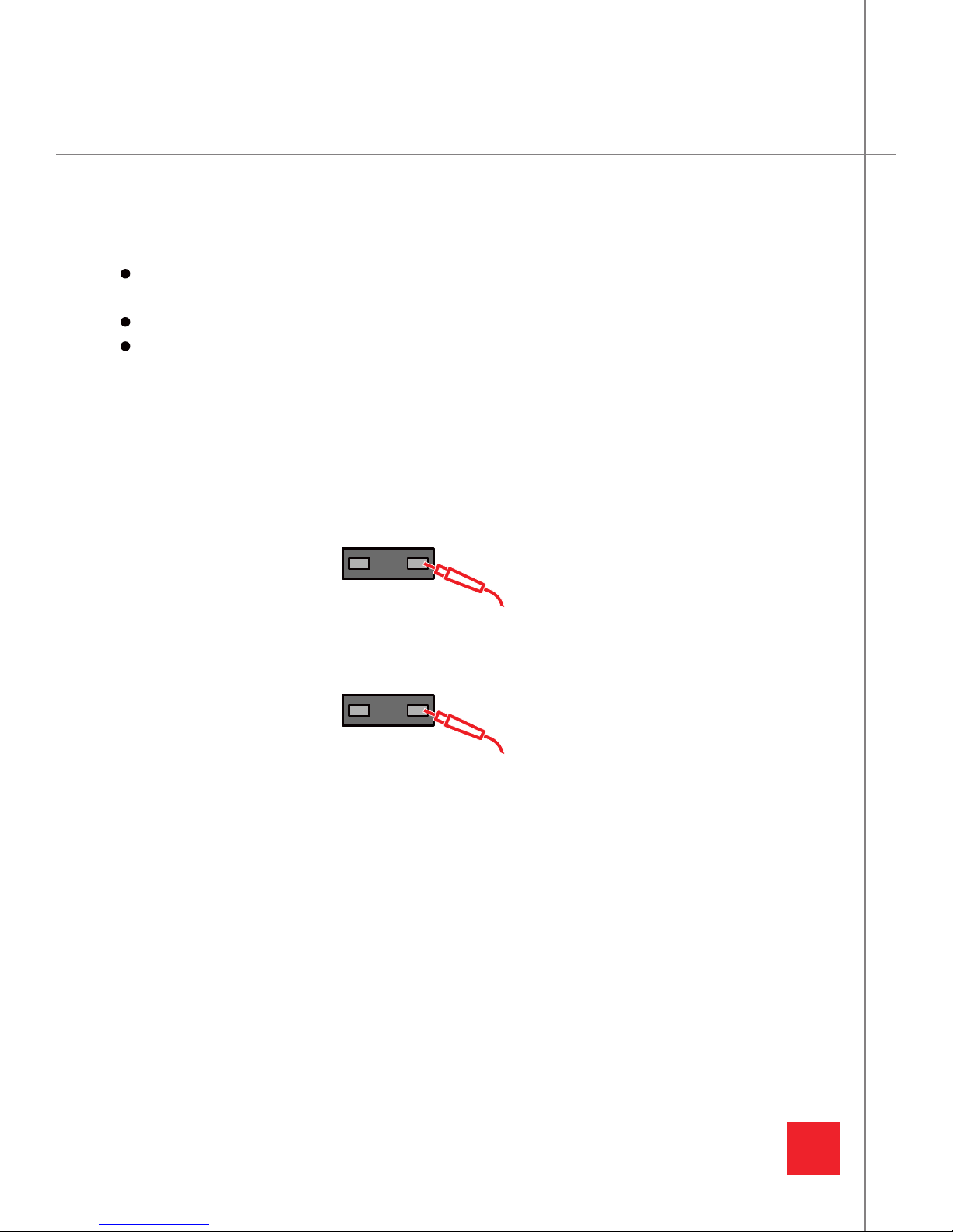
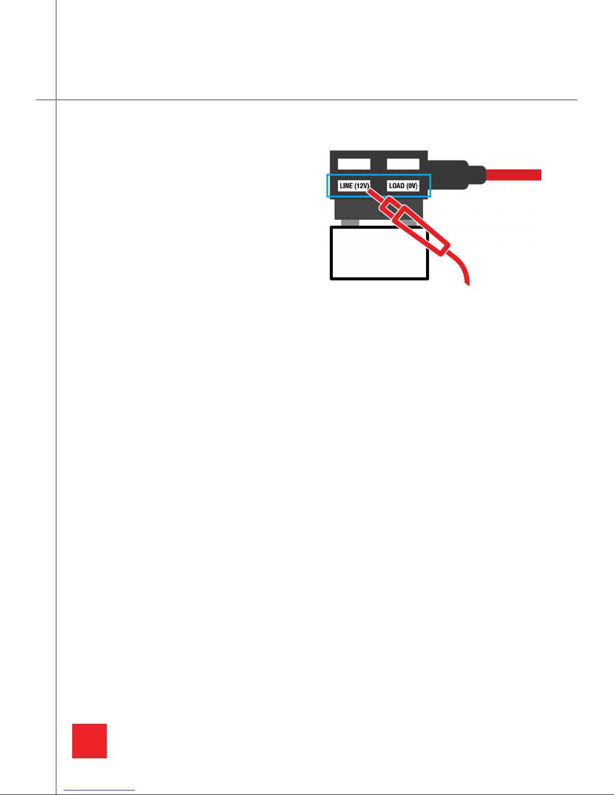
Installation
If you are having issues with installation, please contact professional assistance. GRDIAN is
not reponsible for incorrect wiring and damages due to incorrect installation.
Once installed check to see if other electrical equipments are operating correctly. Incorrect
installation may lead to damage, fire, electrical shock or short circuit.
GRDIAN is not responsible for any installation and uninstallation costs of the product regard-
less of the product’s warranty status.
DO NOT replace fuse other than the original rated capacity. Danger of fire will exist.
GRDIAN is not responsible for the car’s battery life and warranty.
DO NOT install with the vehicle turned ON. Only install with the electrical system on.
Repairing
Do not attempt to repair the device yourself. Doing so will void the Warranty, damage your
device or may cause injury. If your device is damaged or is defective, contact GRDIAN.
Choking hazard
Some accessories may present a choking hazard to small children. Keep these accessories
away from small children.
SAFETY INFORMATION

1
BEFORE INSTALLATION PLEASE CHECK FOR THE FOLLOWING
-CHARGER PLUS
-COMPONENT WIRES (ACC+, BATT+,GND)
-CIGARETTE SOCKET
IN THE BOX

2
LOW VOLTAGE PROTECTION
The Charger Plus will monitor your voltage status and cut-off the power if the voltage drops
below the configured value.
TIMER PROTECTION
Set the amount of time you want to keep your dash cam on by configuring the Charger Plus
timer setting.
OVER CURRENT/SURGE PROTECTION
The Charger Plus will detect abnormal over current status and cut off power to prevent any
damage to your dash cam device. Additionally the Charger Plus has built-in extra fuse box
(2A) to have extra protection if anything goes wrong as incorrect installing or short circuit.
COMPATIBILITY
The Charger Plus is 100% compatible with all GRDIAN products and also compatible with
other dash cam brands. It is universally compatible with other dash cams. Please note not all
dash cams have a Parking Mode feature.
MULTI INPUT POWER DC 12V/24V
Automatically detects voltage input whether your vehicle is running DC12V or 24V.
FEATURES
FEATURES
The GRDIAN Charger Plus is a power management device that keeps your dash cam continuously
running after your engine is turned off. The Charger Plus monitors your vehicle’s battery status
and cuts power off to prevent battery discharge. The Charger Plus comes with low voltage pro-
tection settings, timer protection and over current/surge protection.
WHAT IS THE CHARGER PLUS?

3
Improper installation and handling may cause serious damage to your vehicle. GRDIAN is not
liable for any mishandling and damages resulting from this guide. Install at your own discretion.
Consult your car technician if you continue to have issues. GRDIAN cannot provide help, instruc-
tions or recommendations beyond this guide. Please follow each step accordingly to ensure safe
installation.
GETTING STARTED
MULTIMETER
(NOT INCLUDED)
ADD-A-FUSE
(NOT INCLUDED)
FUSE
(NOT INCLUDED)
CRIMP TOOL
(NOT INCLUDED)
TOOLS NEEDED FOR SETUP
WARNING
PLEASE TAKE THE TIME TO THOROUGHLY UNDERSTAND EACH STEP. SKIPPING A STEPMAY
CAUSE DAMAGE TO YOUR DEVICE AND TO YOUR VEHICLE. GRDIAN IS NOT REPONSIBLE FOR
MISUSE AND INPROPER INSTALLATION. PLEASE CONSULT YOUR CAR TECHNICIAN IF YOU
ARE UNCOMFORTABLE INSTALLING YOUR DEVICE. GRDIAN CANNOT PROVIDE TECHNICAL
SUPPORT REGARDING YOUR VEHICLE OR SUGGESTIONS BEYOND THIS GUIDE. YOUR VEHICLE
‘S ELECTRICAL SYSTEM SHOULD REMAIN COMPELTELY OFF FOR THE DURATION OF THE
INSTALLATION UNLESS SAID OTHERWISE.
BEFORE YOU BEGIN

Locate your fuse box using your Fuse Box Diagram. This information can usually be found in your
vehicle’s User Manual or from your manufacturer’s website.
Once you have located your fuse box, find your battery. The battery is usually located next to the
fuse box.
4
STEP 1: LOCATE YOUR FUSE BOX & BATTERY
LOCATE YOUR FUSE BOX
LOCATE YOUR BATTERY

5
Grounding your wire is crucial to the safety of yourself and your vehicle in the event of a short
circuit. The chassis of your vehicle generally makes a good ground. However, vehicles today are
built with a combination of metals, spot welds, glued together uni-body panels and isolated
chassis components. Therefore, we cannot assume that a good ground will automatically be on
the chassis.
In most vehicles you should be able to locate an obvious ground near the fuse box. Your owner’s
manual may even tell you where the factory ground is. If you are unable to locate a ground point,
we’ll show you how to locate a ground. There are 2 ways to test your ground point.
TESTING YOUR GROUND POINT
CONTINUITY TEST [ SET MULTIMETER TO 200 OHMS ]
1. Set your multimeter to Continuity Test or 200 ohms.
2. Using the black lead, touch the negative (-) terminal of your vehicle’s battery
and then place the red lead on to your ground point. Your multimeter should
beep if it is a complete path. If it does not beep, look for another ground.
RESISTANCE TEST [ SET MULTIMETER TO ]
1. Set your multimeter to Resistance Mode or Diode Check.
2. Using the black lead, touch the negative (-) terminal of your vehicle’s battery
and then place the red lead on to your ground point. A good ground point should read less
than .2 ohms.
Locate a secure bolt on your chassis. Use your multimeter to test.
STEP 2: LOCATE A GROUND POINT
LOCATING A GROUND POINT

6
BEFORE YOU BEGIN
Make sure your vehicle’s electrical system is completely turned OFF before you start.
(Some vehicles may require a couple of minutes of standby for it to completely shut down)
Avoid connecting to fuses over 10A. Use fuses 10A or lower.
DO NOT connect to a fuse relative to car safety (brake lights, cooling fan, TCS, SRS, TPMS,
Fuel Pump, ALT, ECU, etc)
NOTE: Some vehicles maintain their electrical system/power a couple minutes after shutdown.
We recommend opening your doors/trunk for access into your vehicle later. Some vehicles may
require up to ~30 minutes before it completely turns off. Upon returning, avoid opening/closing
any doors or turning on anything. A good indicator of when a vehicle is completely off is when the
cabin lights turn off.
LOCATE A CONSTANT FUSE
1. Set your multimeter to 20 DCV.
2. Use the black lead to touch your ground point.
3. Place the red lead on both ends of the fuse. The multimeter should read ~12V.
LOCATE A SWITCHED FUSE
1. Set your multimeter to 20 DCV.
2. Use the black lead to touch your ground point.
3. Place the red lead on both ends of the fuse. The multimeter should read ~0V.
STEP 3: DETERMINE WHICH FUSES TO USE
CONSTANT & SWITCHED FUSE
10
10

7
HOW TO DETERMINE LINE AND LOAD SIDE
1. Turn on ONLY your vehicle’s electrical system.
2. Set your multimeter to 20 DCV.
3. Remove either your constant or switched fuse. (You will repeat the steps for the other fuse)
4. Insert your add-a-fuse into the empty fuse slot.
5. With the black lead touching your ground point, test for line side by placing the red lead
on the bottom left slot of your add-a-fuse. It should read 12V.
6. With the black lead touching your ground point, test for load side by placing the red lead
on the bottom right slot of your add-a-fuse. It should read 0V.
7. If the above is the case, you have located the line side of your fuse and have placed your
add-a-fuse correctly. If not, remove and place the add-a-fuse in reverse. Repeat steps 6
& 7 to test. Test both slots again to make sure the left bottom slot reads 12V and the right
bottom slot reads 0V.
8. Repeat steps above for the other fuse.
STEP 4: LINE AND LOAD SIDE
LINE AND LOAD SIDE
In this step we will be checking to see which
side of your constant and switched fuse is
line and draw.
With the add-a-fuse inserted, test the line
and load side with your multimeter. The
bottom left slot should read 12V while the
bottom right slot should read 0V.

8
ADD-A-FUSE
Your add-a-fuse will have 2 slots.
The original fuse should be inserted on the bottom, while the new fuse should be inserted at
the top. It does not matter what direction you place the fuse.
NOTE: When inserting, the new fuse should be a lower value than the original fuse. For exam-
ple, the original fuse is 10A. The new fuse should be less than 10A. DO NOT place a same value
amp.
STEP 5: SETTING UP YOUR ADD-A-FUSE
SETTING UP YOUR ADD-A-FUSE

9
Make sure your vehicle’s electrical system is completely OFF for this step.
CRIMPING YOUR WIRES
BATT+ (YELLOW)
Insert and attach the BATT+ wire to your add-a-fuse by using a crimping tool. Once attached,
plug the add-a-fuse into your constant fuse slot. Make sure to insert the add-a-fuse in the
right direction with the line side to line side as determined in Step 4.
ACC+ (RED)
Insert and attach the ACC+ wire to your add-a-fuse by using a crimping tool. Once attached,
plug the add-a-fuse into your switched slot. Make sure to insert the add-a-fuse in the right
direction with the line side to line side as determined in Step 4.
ATTACHING YOUR GND WIRE TO YOUR GROUND POINT
GND (BLACK)
Wrap the GND wire to your ground point and secure it by bolting it down.
Unscrew the ground point and wrap the GND wire around.
Bolt down to secure.
STEP 6: CONNECT YOUR ADD-A-FUSE
CONNECTING ADD-A-FUSE TO THE CHARGER PLUS

10
Your vehicle’s electrical system should be completely OFF. Before connecting, we recommend
setting your voltage setting to the lowest value (11.6V/23.6V).
1. Connect the Cigarette Socket to the OUTPUT terminal of the Charger Plus.
2. Connect the Component Wires to the INPUT terminal of the Charger Plus.
3. Once connected, the Charger Plus should turn on. A RED indicator should light up.
4. Turn on your vehicle’s electrical system. If installed correctly, the Charger Plus should turn
on and the indicator should turn GREEN.
5. Insert your cigarette charger into the Cigarette Socket. Tape down to make sure it is secure.
NOTE: If the Charger Plus is not green, make sure you installed your Charger Plus correctly.
Remove the Input Connection, make sure your vehicle’s electrical system is completely OFF.
Re-establish connection by re-inserting the Input Connection and turning your vehicle’s electri-
cal system ON.
CHECKLIST
Make sure you are using a Constant and Switched Fuse. Refer to Step 3.
Make sure the BATT+ (YELLOW) wire is connected to the Constant fuse slot. Refer to Step 6.
Make sure the ACC+ (RED) wire is connected to the Switched fuse slot. Refer to Step 6.
Make sure your GND wire is properly connected to a ground point. Refer to Step 2 and 6.
Make sure your add-a-fuse is correctly inserted in the right direction. Refer to Step 4.
Remove the Input Connection. Make sure your vehicle’s electrical system is completely OFF.
Insert the Input Connection back in, and turn on your vehicle to test.
STEP 7: TEST THE CONNECTION
TEST THE CONNECTION

11
The Charger Plus will cut off power output to the dash cam when the voltage drops below the set
threshold. Set the voltage setting based on your car’s battery status.
HOW DO I SETUP A VALUE THAT FITS MY VEHICLE?
1. Make sure your vehicle’s electrical status is OFF. Check the voltage value of your vehicle by
using your multimeter. Set the multimeter to 20 DCV. Use the black lead to touch your
ground point and place the red lead on your fuse. Note the voltage.
2. Set the Voltage Protection Setting based on your findings. For example: If the multimeter
detects 12.2V, you may set the voltage setting to 12-11.8V or at least 0.2V lower.
NOTE: Make sure you set the correct voltage setting or your dash cam may keep rebooting. Once
installed, check the camera if it is operating normally. If your dash cam keeps rebooting you may
need to set a lower threshold. If you continue to have issues, have your battery checked by a
professional.
VOLTAGE PROTECTION SETTING

12
The Charger Plus will cut off power output to the dash cam with the built-in timer. Easily set the
amount of time you want your power on by adjusting the timer setting.
TIMER SETTING

13
MODEL
Charger Plus
WEIGHT
3 oz
DIMENSIONS
63.5 x 38 x 25.4mm (2.5 x 1.75 x 1in)
YEAR RELEASED
2019
INPUT INTERFACE
ACC (Red)
GND (Black)
BATT (Yellow)
Cable length (5ft)
OUTPUT INTERFACE
Cigarette Socket
Cable length (5ft)
FUSE
NA
INPUT
12V/24V, 1100mA
RATED OUTPUT VOLTAGE
12V/24V
OUTPUT CURRENT
Rated Current 1A, Max 2A
STANDBY CURRENT (LEAKAGE)
NA
CUTOFF VOLTAGE SETTING
11.6V - 12.5V (11.6, 11.9, 12.2, 12.5)
23.6V - 24.5V (23.6, 23.9, 24.2, 24.5)
OUTPUT RECOVERY VOLTAGE
NA
OUTPUT CUT-OFF TIMER SETTING
2 hours, 4 hours, 6 hours, 12 hours, 24
hours, Always On
OPERATING TEMPERATURE
-20˚°C to 75˚°C (-4°F to 167°F)
PROTECTION
Low Voltage Protection
Timer Protection
Over Current/Surge Protection
PRODUCT SPECIFICATIONS

14
TRADEMARKS
Warranty is limited to 1 year (12 months) from the date of delivery. Valid proof of purchase
is required to obtain warranty services. Warranty is only valid where the product is sold. If
purchased from other than GRDIAN.COM reciept is required.
GRDIAN, the GRDIAN logo, the Charger Plus logo, Capture the Unexpected are trademarks or
registered trademarks of GRDIAN, LLC in the U.S. and internationally. Other names and marks are
the property of their respective owners
WARRANTY
CUSTOMER SUPPORT
SUPPORT
GRDIAN is dedicated to providing the best possible services and products. To reach out to our
support team, please visit: www.grdian.com/contact-us
MESSAGE US
We make ourselves available to you on different social media platforms. You can reach out to us
on Twitter, Facebook, and Instagram.
For more answers to commonly asked questions, see
grdian.com/support.

WWW.GRDIAN.COM
Table of contents