Greenheck ERM-36 Series User manual

GREENHECK
P.O. BOX 410 SCHOFIELD, WISCONSIN 54476-0410
PH. 715-359-6171
INSTALLATION, OPERATION AND MAINTENANCE MANUAL
**WARNING**
DISCONNECT ALL ELECTRICAL POWER TO THE ERM PRIOR TO INSPECTION OR SERVICING.
FAILURE TO COMPLY WITH THIS SAFETY PRECAUTION COULD RESULT IN SERIOUS INJURY OR DEATH.
READ AND SAVE THESE INSTRUCTIONS
INSTALLATION
Greenheck Energy Recovery Modules (ERM) are thoroughly inspected
and test run at the factory, however damage may occur during handling
and shipping. Consequently, it is important to inspect the unit for visible
and concealed damage before beginning installation. Report any
damage to the shipper immediately. Turn the wheel by hand (clockwise
as viewed from the pulley side) to verify the wheel rotates freely. In
addition, assure all accessory items are present.
ELECTRICAL CONNECTIONS
The electrical supply must be compatible with that shown on the wheel
drive motor nameplate: voltage, phase, and amperage capacity (see
page 2 for specific requirements). Units are supplied with a receptacle
for the cassette plug and service box for wiring. Connect the ERM
wiring directly to blower wiring or to blower fan relay to assure power to
the ERM whenever fan is in operation. All wiring must be properly fused
and conform to local and national electrical codes.
DO NOT OPERATE THE ERM FOR ANY EXTENDED PERIOD WITHOUT
AIRFLOW ACROSS THE ENERGY WHEEL AS THE DRIVE MOTOR IS
COOLED BY THE AIRFLOW.
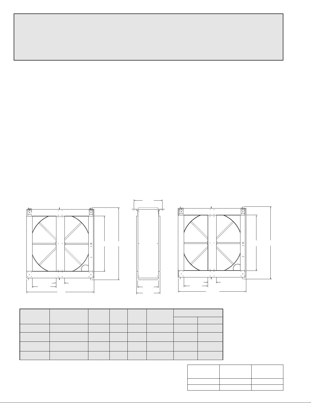
MOUNTING
The ERM is shipped with a mounting kit, which contains four hanging brackets, fasteners and a separate instruction sheet with
parts list. These brackets will support the ERM in either the vertical or horizontal position for design flexibility. A 3/8"x3/4" hex
head bolt is located at each corner of the ERM for attaching these brackets. To hang
the ERM:
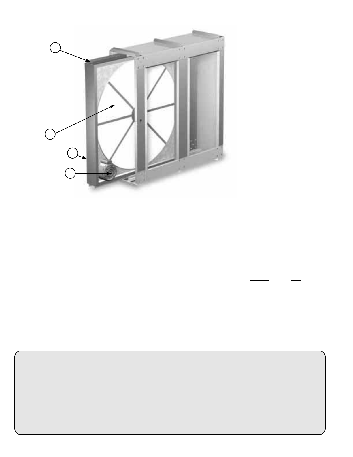
Note: To reduce unit weight for handling purposes, the cassette may be removed from
the cabinet (reduces ERM-36 from 155 lbs. to 75 lbs., reduces ERM-52 from 280 lbs. to
110 lbs.).
1. To remove the cassette from the cabinet, remove the access panel and unplug the
wheel drive motor at the electrical receptacle in the cabinet.
2. Replace the access panel before mounting to insure squareness.
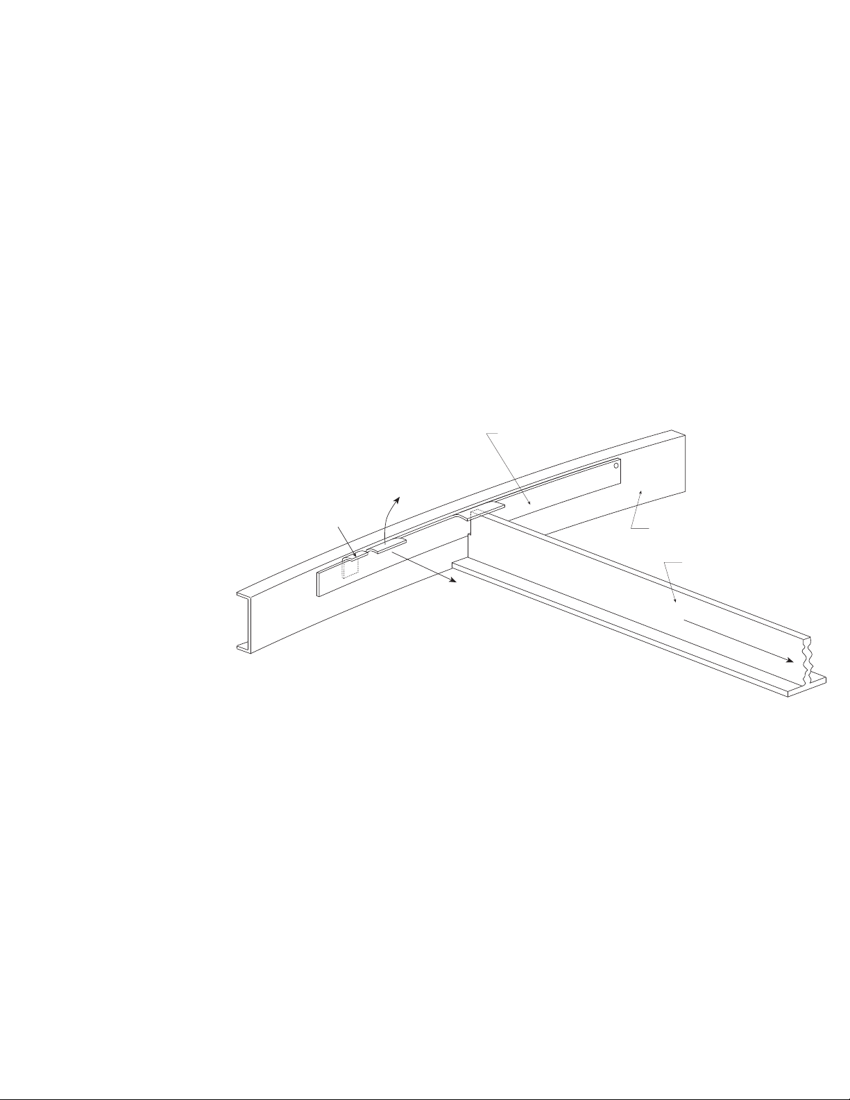
3. Remove the appropriate four bolts from the ERM and use to
secure the brackets as shown in Figure 1. These brackets are
designed for 3/8" threaded hanging rods.
4. To reinstall the cassette in the mounted ERM cabinet, align
the cassette sliders with the channels in the cabinet and slide
the cassette in place. Replace access panel when finished.
IMPORTANT: ERM MUST BE INSTALLED SUCH THAT THE
ENERGY WHEEL CASSETTE SLIDES IN AND OUT OF THE
CABINET PARALLEL TO THE FLOOR.
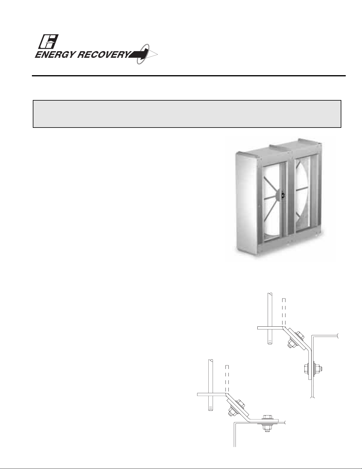
ENERGY RECOVERY MODULES
Models ERM-36 & 52
FIGURE 1
Part # 456785

2
PRESTART
START-UP
After installation is complete, remove the cassette access panel and determine that the energy wheel rotates freely by hand.
Apply power and observe that the wheel rotates (at approximately 60 RPM). If the wheel does not rotate when power is
applied, it will be necessary to readjust excessively tight diameter air seals.
AIR SEAL ADJUSTMENT
If wheel does not rotate or rotates too slowly, remove the access panel and slide the cassette half way out of the ERM
cabinet.
Overly tight air seals will prevent proper rotation of the energy recovery wheel. Recheck the air seals for tightness. Air seal
clearance may be checked by placing two sheets of paper (typically each 0.004" thick), like a feeler gauge, against the wheel
face. A loose slip grip should exist between the wheel and seals. To adjust the air seals, loosen all eight seal retaining screws.
These screws hold the four separate seal retaining plates to the bearing support channels. Slide the seals away from the
wheel. Use the paper feeler gauge to readjust and retighten one seal plate at a time to provide a slip fitting clearance when
the wheel is rotated by hand.
Once seals are adjusted, replace the cassette. Confirm that the wheel rotates freely by hand and when power is applied.
Replace access panel.
DIMENSIONAL DATA
INSTALLATION CLEARANCES
Specifications
Weight
Model Voltage Hertz Amps Phase Motor HP Cabinet Cassette
ERM-36S 200-208/240v 50/60 1.2 1 1/6 75 80
ERM-36H 200-208/240v 50/60 1.2 1 1/6 75 92
ERM-52S 200-208/240v 50/60 2.8 1 1/2 110 170
ERM-52H 200-208/240v 50/60 2.8 1 1/2 110 170
341/4
Mtg. Centers
441/2
42
147/8
5
125/8
145/8
177/8
61/2
581/4
223/8
505/8603/4
ERM-36 ERM-52
**WARNING**
DO NOT OPERATE ENERGY RECOVERY MODULE WITHOUT DUCT FILTERS OR SCREENS INSTALLED.
THE FILTERS AND SCREENS PREVENT THE ENTRY OF FOREIGN OBJECTS SUCH AS LEAVES, BIRDS, ETC.
DO NOT REMOVE ACCESS PANELS WHILE STANDING ON A LADDER OR OTHER UNSTEADY BASE.
ACCESS PANELS ARE HEAVY AND SERIOUS INJURY MAY OCCUR.
Provide proper clearance for cassette inspection, service or removal. Do not
install ducting, piping or wiring where it will interfere with cassette removal.
Removal
Inspection
or Service
Model
ERM-36 22" 42"
ERM-52 30" 58"

CLEANING ENERGY RECOVERY WHEEL SEGMENTS
DISCOLORATION AND STAINING OF ENERGY RECOVERY WHEEL DOES NOT AFFECT ITS PERFORMANCE.
If the wheel appears excessively dirty, it should be cleaned to ensure maximum operating efficiency. Only excessive buildup of
foreign material needs to be removed. Segments can be vacuumed or if more intense cleaning is necessary see the following
instructions.
Thoroughly spray wheel matrix with household cleaner such as FantasticTM or equivalent. Gently rinse with warm water and
using a soft brush remove any heavier accumulation. A detergent/water solution can also be used. Avoid aggressive organic
solvents, such as acetone. The segments can be soaked in the above solution overnight for stubborn dirt or accumulation.
After cleaning is complete, shake the excess water from the wheel or segments. Dry segments before replacing them back into
the cassette. Replace segments back into cassette by reversing removal procedures.
DO NOT CLEAN ENERGY RECOVERY SEGMENTS WITH WATER IN EXCESS OF 140°F.
DO NOT DRY ENERGY RECOVERY SEGMENTS IN AIR TEMPERATURES IN EXCESS OF 140°F.
ROUTINE MAINTENANCE
CAUTION: See **WARNING** on Page 1 and 2
Annual inspection of the energy recovery wheel is recommended for ERM units. Routine maintenance includes periodic
inspection of energy recovery wheel segments, drive belts, air seals and duct filters. ERM units ventilating smoking lounges and
other non-clean air spaces should have energy recovery wheel inspections more often based upon need.
ACCESSING ENERGY RECOVERY WHEEL
Disconnect power to the ERM unit. Remove access panel and UNPLUG the wheel drive motor. Pull the cassette halfway out.
Then rotate the wheel, by hand, clockwise (viewed from the pulley side of cassette) to check each segment.
REMOVING THE ENERGY RECOVERY WHEEL SEGMENTS
Model ERM-36 & ERM-52 - Steel retainers are located on the inside of the wheel rim (See Figure 2). Push the retainer
towards center of wheel, then lift up and away to release segments.
Reverse the above instructions to reinstall the energy recovery wheel segments.
NOTE: PLACE RETAINERS
BACK IN THE ORIGINAL
POSITION BEFORE
ROTATING THE ENERGY
RECOVERY WHEEL.
OTHERWISE DAMAGE TO
RETAINER WILL OCCUR.
Bracket Segment Retainer
Lift Away
From Segment
Catch-
Segment Retainer
Push Toward Center
Center of Wheel
Spoke
Inside of Wheel Rim
FIGURE 2
3

4
PARTS LIST
1. Removable energy recovery wheel cassette Model GFC Part Number
including drive motor, pulley and belt. ERM-36S 335293
ERM-36H 335294
ERM-52S 335295
ERM-52H 335296
2. Removable energy recovery ERM-36S 335305
wheel segments. ERM-36H 335306
ERM-52S 335307
ERM-52H 335308
3. Energy recovery wheel drive Pulleys Belt
belt and pulley ERM-36S 351517 456492
ERM-36H 351517 456492
ERM-52S 351518 457124
ERM-52H 351518 457124
4. Energy wheel drive motor ERM-36S 303478
ERM-36H 303478
ERM-52S 303480
ERM-52H 303480
IOM ERM 36/52 - 98 R
1
2
4
3Note: ERM mounting bracket
kit has a separate parts list
and instruction sheet.
WARRANTY
Greenheck warrants this equipment to be free from defects in material and workmanship for a period of five years from
the purchase date. This warranty limits our responsibility to repairing or replacing, to the original purchaser, any part or
parts of said equipment found to be defective upon examination by representatives of Greenheck. Additionally, said part
or parts will be returned to and received by the factory only after prior authorization, with transportation charges prepaid.
Greenheck shall not be obligated under this warranty, for payment of any delivery, removal or installation charges with
regard to repair or replacement of any defective part or parts.
Motors are warranted by the motor manufacturer for a period of one year. Should motors furnished by Greenheck prove
defective during this period, they should be returned to the nearest authorized motor service station.
This manual suits for next models
5
Table of contents
Other Greenheck Test Equipment manuals
Popular Test Equipment manuals by other brands

QuadTech
QuadTech Guardian 2500 Series instruction manual

Alps Electric
Alps Electric SC Linear Leak Tester quick start guide

Microchip Technology
Microchip Technology CSIII user guide

Klein
Klein 3000 Series quick start guide

TECALEMIT
TECALEMIT DE 7288/2005 Installation operation & maintenance

PANCONTROL
PANCONTROL PAN Leitungssucher manual