94455 Boeing Dr., Rockford, IL 61109-2988 815/397-7070
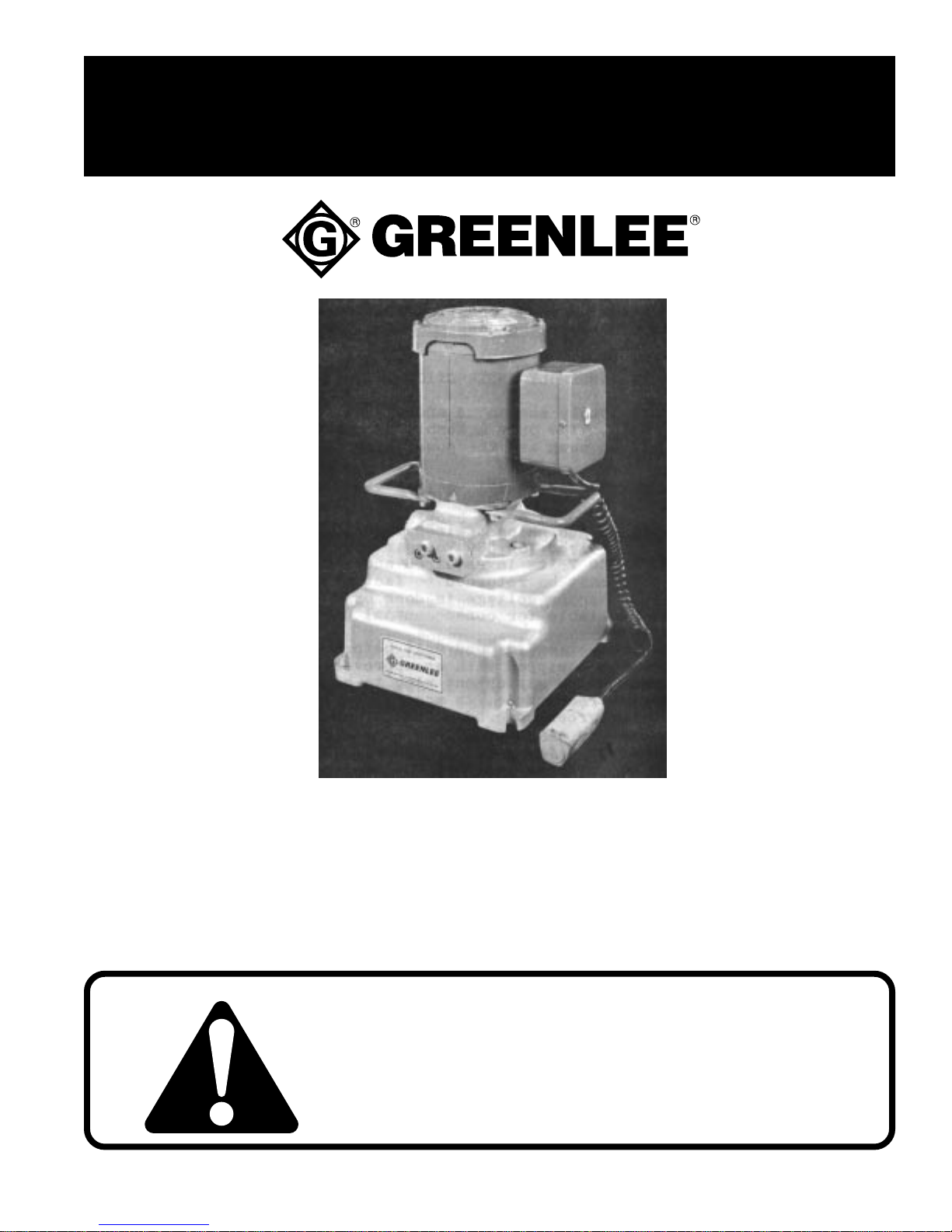
Hydraulic Power Pumps
Greenlee Textron / Subsidiary of Textron
Hydraulic Power Pumps — Parts List
940-M3-PO-PS (501 8608.6)
960-M3-PO-PS (501 0860.6)
Key Part No. Description Qty
A 501 8621.3 Block Unit, PO Pump (1-43) ..............................................................1
1 500 6067.8. Valve Unit, Relief...............................................................................1
2 501 7766.4 Valve Unit, Relief...............................................................................1
3 501 7345.6 Plate, Pump Mounting .......................................................................1
4 501 8871.2 Spacer, Bearing.................................................................................1
5 501 1855.2 Race, Outer .......................................................................................1
6 501 1862.5 Plug, Plunger.....................................................................................1
7 501 9060.1 Plunger, High Pressure .....................................................................1
8 502 0424.6 Block, Intake ......................................................................................1
9 501 4861.3 Plate, Pump .......................................................................................1
10 501 4862.1 Key.....................................................................................................1
11 501 4876.1 Shaft, Eccentric .................................................................................1
12 501 5958.5 Piston, Valve......................................................................................1
13 501 7130.5 Plate, Top ..........................................................................................1
14 501 7131.3 Plate, Bottom .....................................................................................1
15 501 7135.6 Vane ..................................................................................................4
16 501 7136.4 Rotor..................................................................................................1
17 501 7347.2 Stop, Valve Piston .............................................................................1
18 501 7348.0 Plunger, Release...............................................................................1
19 501 7467.3 Dowel, Hollow....................................................................................1
20 501 8238.2 Adapter, Drive Shaft ..........................................................................1
21 501 8622.1 Block, PO Pump ................................................................................1
22 500 6111.9 Spring, Compression.........................................................................5
23 501 9059.8 Bushing, Plunger ...............................................................................1
24 501 4865.6 Spring, Compression.........................................................................1
25 501 4893.1 Spring, Compression.........................................................................1
26 502 1175.7 Screen, Intake ...................................................................................1
27 905 0436.4 Ball, 9/32 Chrome Steel ....................................................................2
29 905 0501.8 Plug, 1/8 NPT Socket Head Pipe ......................................................1
30 905 0577.8 Screw, #10-32 NF x 3/4 Socket Head Cap .......................................6
31 905 0680.4 Ball, 5/16 Chrome Steel ....................................................................1
32 905 0681.2 Ball, 3/8 Chrome Steel ......................................................................1
33 905 1526.9 Washer, #8 Hi-Collar Lock ................................................................4
34 905 0824.6 Plug, 1/16 NPT Socket Head Pipe ....................................................7
35 905 0839.4 O-Ring, 1-3/8 x 1-1/2 x 1/16..............................................................2
36 502 2611.8 Roller, 1/8 x 3/4 ...............................................................................30
37 905 1524.2 O-Ring, 1/2 x 5/8 x 1/16 ....................................................................1
38 905 0989.7 Bearing, .7874 ID x 2.0472 OD x .5906 Thick ..................................1
39 905 0994.3 Screw, #8-32 NC x 1-1/4 Socket Head Cap......................................4
40 905 1111.5 Screw, 7/16-20 NF x 1/2 Cup Point Socket Set ................................1
41 905 1215.4 O-Ring, 7/16 x 9/16 x 1/16 ................................................................1
42 905 1337.1 Screw, 5/16-24 NF x 5/32 Socket Jam..............................................2
43 905 1473.4 Bearing, .9843 ID x 2.0472 OD x .5906 Thick Ball ...........................1
C 502 0721.0 Cord Unit, PS Power (52 & 60-65) ....................................................1
52 503 2363.6 Switch, Pendant.................................................................................1
60 501 8443.1 Enclosure, Relay ...............................................................................1
61 918 5117.3 Connector ..........................................................................................2
62 918 5264.1 Cord, 10-foot......................................................................................1
63 918 5364.8 Relay, 115 Volt ..................................................................................1
64 905 1523.4 Screw, #6 x 3/8 Slotted Sheet Metal .................................................2
65 905 1252.9 Screw, #6-32 NC x 1/4 Round Head Thread Cutting........................2
66 501 5646.2 Dipstick Unit.......................................................................................1