94455 Boeing Dr., Rockford, IL 61109-2988 815/397-7070
Greenlee Textron / Subsidiary of Textron
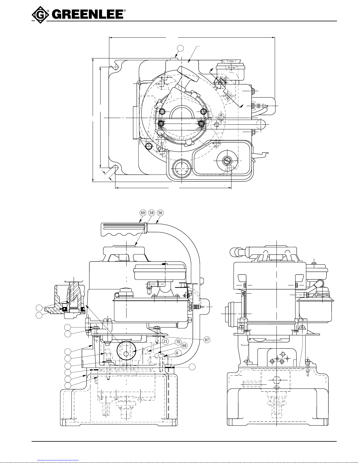
950-M3 Basic Hydraulic Power Pump
KEY PART NO. DESCRIPTION QTY.
A 503 3333.0 Block unit, pump (consists of 1 and 3 - 39 except 21) ............1
1 500 6067.8 Valve unit, relief (10,000/10,400 psi) .......................................1
2 501 7766.4 Valve unit, relief (200/225 psi) .................................................1
3 501 8194.7 Plate, pump mounting..............................................................1
4 500 3493.6 Pin, seal, .125 x .500 ...............................................................1
5 501 8871.2 Spacer, bearing........................................................................1
6 501 1855.2 Race, outer ..............................................................................1
7 501 1862.5 Plug, high-pressure plunger.....................................................1
8 501 9060.1 Plunger, high-pressure ............................................................1
9 501 9059.8 Bushing, high-pressure plunger...............................................1
10 502 0424.6 Block, intake.............................................................................1
* 11 501 4861.3 Plate, pump..............................................................................1
* 12 501 4862.1 Key, lo-pressure pump.............................................................1
13 501 4876.1 Shaft, eccentric ........................................................................1
* 14 501 7130.5 Plate, top..................................................................................1
* 15 501 7131.3 Plate, bottom............................................................................1
* 16 501 7135.6 Vane.........................................................................................4
* 17 501 7136.4 Rotor ........................................................................................1
18 501 7467.3 Dowel, hollow...........................................................................1
19 905 1473.4 Bearing, single row unshielded ball .........................................1
20 501 8237.4 Block, pump .............................................................................1
21 502 2701.7 Adapter, drive shaft..................................................................1
+ 22 500 6111.9 Spring, compression ................................................................1
+ 23 501 4865.6 Spring, compression ................................................................1
24 502 1175.7 Screen, intake ..........................................................................1
25 905 1472.6 Lok-dowel, 1/4 x 3/4.................................................................2
+ 26 905 0436.4 Ball, steel, 9/32 diameter .........................................................2
27 501 8195.5 Plunger, check valve................................................................1
+ 28 905 0677.4 Ball, steel, 5/32 diameter .........................................................1
+ 29 905 0681.2 Ball, steel, 3/8 diameter ...........................................................1
30 905 1526.9 Washer, lock, .172 x .267 x .045 spring ..................................4
+ 31 905 0014.8 O-ring, .625 x .750 x .062 ........................................................1
@ 32 905 0911.0 Roller, .125 x .750 (to replace, see the Optional
Repair Kits)........................................................................30
+ 33 905 1524.2 O-ring, .500 x .625 x .062 ........................................................1
34 905 0989.7 Bearing, single row unshielded ball .........................................1
35 905 0994.3 Screw, cap, #8 - 32 x 1-1/4 socket head .................................4
36 905 1111.5 Screw, set, 7/16 - 20 x 1/2 socket ...........................................1
37 905 2817.4 O-ring, .438 x .563 x .062 ........................................................1
38 905 1241.3 Screw, set, #10 - 32 x 3/16 socket flat point............................1
39 905 1471.8 Screw, cap, #10 - 32 x 7/8 socket head ..................................6
40 905 1472.6 Lok-dowel, 1/4 x 3/4.................................................................2
52 501 7209.3 Dipstick ....................................................................................1
53 501 5695.0 Reservoir..................................................................................1
Parts List